DriSteem Vaporstream VLDI 5-1 Installation, Operation and Maintenance Manual

Category
Socket-outlets
Type
Installation, Operation and Maintenance Manual
Vaporstream
®
Electric Humidifier
Installation, Operation
and Maintenance Manual
Vaporstream_IOM.pdf 1 3/15/2010 1:53:11 PM
1BHF**t%3*45&&.7BQPSTUSFBN*OTUBMMBUJPO0QFSBUJPOBOE.BJOUFOBODF.BOVBM
ATTENTION INSTALLER
Read this manual before installing.
Leave manual with product owner.
DRI-STEEM
®
technical support
800-328-4447
WARNING!
Disconnect electrical power before installing supply wiring. Contact with
energized circuits can cause severe personal injury or death as a result
of electrical shock.
This product must be installed by qualified HVAC and electrical
contractors and in compliance with local, state, federal, and governing
codes. Improper installation can cause property damage, severe
personal injury, or death as a result of electric shock, burns, and/or fire.
The humidifier tank, dispersion assembly, and all connected hose or
piping can contain or discharge hot steam and/or hot water at 212 °F
(100 °C). Discharged steam is not visible. Contact with hot surfaces,
discharged hot water, or air into which steam has been discharged can
cause severe personal injury.
Failure to follow the instructions in this manual can cause moisture to
accumulate, which can cause bacteria and mold growth or dripping
water into building spaces. Dripping water can cause property damage;
bacteria and mold growth can cause illness.
Supply water pressure greater than 80 psi (550 kPa) can cause the
humidifier to overflow.
Vaporstream_IOM.pdf 2 3/15/2010 1:53:16 PM
%3*45&&.7BQPSTUSFBN*OTUBMMBUJPO0QFSBUJPOBOE.BJOUFOBODF.BOVBMt1BHF
5BCMFPGDPOUFOUT
Keypad and troubleshooting
information
The
Vapor-logic
®
3
Installation and Operation
Manual,
which was shipped with your
humidifier, is a comprehensive operation
manual. Refer to it for information about
using the keypad and for troubleshooting
information.
Download DRI-STEEM literature
Most DRI-STEEM
®
product manuals can be
downloaded, printed, and ordered from our
web site: www.dristeem.com
Overview
Model VLC ............................................2
Model VLDI ...........................................3
Specifications ...........................................4
Dimensions ............................................5
Weights and cabinet sizes ................................6
Installation
Selecting a location ......................................7
Mounting
Support legs ........................................9
Trapeze hanger ....................................10
Wall brackets .....................................11
Weather cover .........................................12
Outdoor enclosure ....................................14
Piping
Overview ..........................................23
Drain .............................................25
Water supply ......................................27
Wiring ...............................................29
Humidistat and transmitter placement ....................33
Dispersion
General instructions ................................34
Interconnecting piping requirements .................35
Drip tee installation ................................37
Single tube and multiple tube ........................38
Rapid-sorb ........................................43
SDU-I ............................................50
SDU-E ............................................52
Area-type fan ......................................55
Operation
Start-up procedure .....................................57
Maintenance
Standard water models .................................58
DI water models .......................................62
Outdoor enclosure .....................................64
Replacement parts
Humidifier tank .......................................66
Control cabinet ........................................68
SDU-I ................................................70
SDU-E ...............................................71
Outdoor enclosure .....................................72
Warranty
. ..............................................Back cover
Vaporstream_IOM.pdf 3 3/15/2010 1:53:16 PM
1BHFt%3*45&&.7BQPSTUSFBN*OTUBMMBUJPO0QFSBUJPOBOE.BJOUFOBODF.BOVBM
Standard water models (Model VLC)
Vaporstream VLC humidifiers use electricity to heat potable or
softened fill water into steam for humidification. A conductivity
probe monitors water level, requiring water conductivity to be at
least 100 μS/cm to operate properly. Therefore, VLC models will
not operate with demineralized water. For demineralized water
operation (using deionized or reverse osmosis treated water), use
VLDI model humidifiers (described on next page).
Figure 2-1:
Vaporstream
®
Model VLC (standard water model) system example
OM-628
Control cabinet
Probe
Dispersion tube
Duct
Cover
Steam outlet
Skimmer port outlet
Fill valve
Needle valve
Drain valve
Cleanout tray
Field drain connection
Thermal trip
Cover fastener
Field
connection
terminal strip
Temperature sensor
Heaters
Vapor-logic
3
Important notes:
t 7BQPSTUSFBN7-$TUBOEBSEXBUFS
models can be converted in the field for
use with deionized/reverse osmosis (DI/
RO) water. Vaporstream VLDI (DI water)
models can be converted in the field for
use with potable or softened water.
t %BNBHFDBVTFECZDIMPSJEFDPSSPTJPO
is not covered by your DRI-STEEM
®
warranty.
.PEFM7-$
Overview
Vaporstream_IOM.pdf 4 3/15/2010 1:53:16 PM
%3*45&&.7BQPSTUSFBN*OTUBMMBUJPO0QFSBUJPOBOE.BJOUFOBODF.BOVBMt1BHF
.PEFM7-%*
Figure 3-1:
Vaporstream Model VLDI (DI/RO water model)
OM-1000
Cover fastener
Cover
Float valve
Overflow
Low-water cutoff
Drain valve
Deionized water models (Model VLDI)
Vaporstream VLDI humidifiers use electricity to heat
deionized (DI) or reverse osmosis (RO) fill water into steam for
humidification. VLDI models control water level using a float valve
with low water cutoff switch.
VLDI models are virtually maintenance-free and require very little
or no downtime.
Systems using tap or softened water control
water levels electronically using a three-rod
probe. The controller responds with the
above actions when the water level reaches
each rod.
Fill valve closes
Fill valve opens
Low-water cutoff
Figure 3-2:
Water level control for standard
water systems
VLC-OM-030
Figure 3-3:
Water level control for DI/RO
water systems
Supply water connection
Float rod
Note:
See Pages 23 and 24 for detailed
installation drawings.
Systems using deionized (DI) water or water
that has been treated through reverse
osmosis (RO) control water levels using a
float valve and low water cutoff switch.
Float ball
VLC-OM-026
Overview
Vaporstream_IOM.pdf 5 3/15/2010 1:53:18 PM
1BHFt%3*45&&.7BQPSTUSFBN*OTUBMMBUJPO0QFSBUJPOBOE.BJOUFOBODF.BOVBM
4QFDJGJDBUJPOT
Table 4-1:
Vaporstream capacities and electrical specifications
VLC
VLDI
model
(kW-
stages)
Maximum
steam capacity
Heaters
Current draw (amps)
kWSingle-phase Three-phase***
lbs/hr kg/h Qty.
Stages**
120V 208V* 240V* 480V* 600V* 208V* 240V* 480V* 600V*
2-1 5.7 2.6 1 1 16.7 9.6 8.3 4.2 3.3 2
3-1 8.6 3.9 1 1 25.0 14.4 12.5 6.3 5.0 3
4-1 11.4 5.2 1 1 33.3 19.2 16.7 8.3 6.7 4
5-1 15.2 6.9 1 1 25.6 22.2 11.1 8.9 5.33
6-1 17.1 7.8 3 1 28.8 25.0 12.5 10.0 16.7 14.4 7.2 5.8 6
9-1 25.7 11.6 3 1 43.3 37.5 18.8 15.0 25.0 21.7 10.8 8.7 9
12-1 34.2 15.5 3 1 25.0 20.0 33.3 28.9 14.4 11.5 12
16-1 45.6 20.7 3 1 33.3 26.7 44.4 38.5 19.2 15.4 16
21-1 59.9 27.1 3 1 43.8 35.0 25.3 20.2 21
25-1 71.3 32.3 3 1 41.7 30.1 24.1 25
12-2 34.2 15.5 6 2 57.7 50.0 25.0 20.0 33.3 28.9 14.4 11.5 12
18-2 51.3 23.3 6 2 86.5 75.0 37.5 30.0 50.0 43.3 21.7 17.3 18
24-2 68.4 31.0 6 2 50.0 40.0 66.6 57.7 28.9 23.1 24
32-2 91.2 41.4 6 2 66.7 53.3 88.8 77.0 38.5 30.8 32
42-2 119.7 54.3 6 2 87.5 70.0 50.5 40.4 42
50-2 142.5 64.6 6 2 83.3 60.1 48.1 50
18-3 51.3 23.3 9 3 86.5 75.0 37.5 30.0 50.0 43.3 21.7 17.3 18
27-3 77.0 34.9 9 3 129.8 112.5 56.3 45.0 74.9 65.0 32.5 26.0 27
36-3 102.6 46.5 9 3 75.0 60.0 99.9 86.6 43.3 34.6 36
48-3 136.8 62.0 9 3 100.0 80.0 133.2 115.5 57.7 46.2 48
63-3 179.6 81.4 9 3 131.3 105.0 75.8 60.6 63
75-3 213.8 96.9 9 3 125.0 90.2 72.2 75
24-4 68.4 31.0 12 4 115.4 100.0 50.0 40.0 66.6 57.7 28.9 23.1 24
36-4 102.6 46.5 12 4 173.1 150.0 75.0 60.0 99.9 86.6 43.3 34.6 36
48-4 136.8 62.0 12 4 100.0 80.0 133.2 115.5 57.7 46.2 48
64-4 182.4 82.7 12 4 133.3 106.7 177.6 154.0 77.0 61.6 64
84-4 239.4 108.6 12 4 — 175.0 140.0 — — 101.0 80.8 84
100-4 285.0 129.3 12 4 166.7 120.3 96.2 100
Notes:
* If using an optional SDU or Area-type™ fan unit for dispersion, run a neutral line with 208V/240V/single-phase and 208V/three-phase power supply lines to
provide a 120V circuit for the fan. With all other power supply voltages (other than 120V), provide a separate 120V circuit for the fan, or order from DRI-STEEM a
transformer installed in the control cabinet.
** Heater stage identifies the number of contactors.
*** Three-phase power supply connection. All heater loads are wired Delta.
Total humidifier load = load to meet design conditions + load to compensate for steam loss from the dispersion assembly and interconnecting piping. If
total humidifier load is more than the humidifier's maximum capacity, design conditions will not be met. For steam loss data see the DRI-STEEM Design Guide
available for downloading and printing at www.dristeem.com
Overview
Vaporstream_IOM.pdf 6 3/15/2010 1:53:19 PM
%3*45&&.7BQPSTUSFBN*OTUBMMBUJPO0QFSBUJPOBOE.BJOUFOBODF.BOVBMt1BHF
Overview
%JNFOTJPOT
Table 5-2:
Vaporstream dimensions
VLC/VLDI model (kW - stages)
Without mounted control cabinet
A (length) B (width) C (height)
inches mm inches mm inches mm
2-1, 3-1, 4-1, 5-1 12.52 318 26.00 660 18.88 480
6-1, 9-1, 12-1, 16-1, 21-1, 25-1 17.85 453 22.00 559 18.88 480
12-2, 18-2, 24-2, 32-2, 42-2, 50-2 25.35 644 22.00 559 18.88 480
18-3, 27-3, 36-3, 48-3, 63-3, 75-3 32.85 834 22.00 559 18.88 480
24-4, 36-4, 48-4, 64-4, 84-4, 100-4 40.35 1025 22.00 559 18.88 480
VLC/VLDI model (kW - stages)
With mounted control cabinet option
Max. control
cabinet size
A’ (length 2) B’ (width 2) C’ (height 2)
inches mm inches mm inches mm
2-1, 3-1, 4-1, 5-1 M 14.75 375 34.00 864 30.31 770
6-1, 9-1, 12-1, 16-1, 21-1, 25-1 M 25.00 635 30.00 762 30.31 770
12-2, 18-2, 24-2, 32-2, 42-2, 50-2 L 29.00 737 30.00 762 34.11 866
18-3, 27-3, 36-3, 48-3, 63-3, 75-3 XXL 32.85 834 32.00 813 46.11 1171
24-4, 36-4, 48-4, 64-4, 84-4, 100-4 XXL 40.35 1025 32.00 813 46.11 1171
Notes:
t'PSBMM7BQPSTUSFBNNPEFMTXJUIPQUJPOBMJOTVMBUJPOBEENNUPEJNFOTJPOT"$BOE$
t%JNFOTJPOTBSFMBSHFTUQPTTJCMFGPSUIFTFNPEFMT"DUVBMEJNFOTJPOTNBZCFTNBMMFS
Table 5-1:
Standard control cabinet dimensions and weights
Cabinet
size
Cabinet dimensions
Shipping
weight*
inches mm lbs kg
S 16 h x 14 w x 6 d 406 h x 356 w x 152 d 32 15
M 20 h x 20 w x 7 d 508 h x 508 w x 178 d 55 25
L 24 h x 24 d x 7 d 610 h x 610 w x 178 d 73 33
XL 30 h x 24 w x 9 d 762 h x 610 w x 229 d 91 41
XXL 36 h x 30 w x 9 d 914 h x 762 w x 229 d 136 62
Notes:
* In addition to shipping weight of humidifier
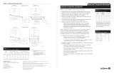
Figure 5-1:
Vaporstream dimensions
VLC-OM-039
C
#
C'
A
B
"
Vaporstream_IOM.pdf 7 3/15/2010 1:53:19 PM
1BHFt%3*45&&.7BQPSTUSFBN*OTUBMMBUJPO0QFSBUJPOBOE.BJOUFOBODF.BOVBM
Table 6-1:
Vaporstream weights and control cabinet sizes by model
VLC
VLDI
model
(kW-
stages)
Shipping
weight
Operating
weight †
Control cabinet size*
(M, L, XL, XXL)
Single-phase power Three-phase power
lbs kg lbs kg 120V 208V 240V 480V 600V 208V 240V 480V 600V
2-1 35 16 79 36 M M M M M
3-1 35 16 79 36 M M M M M
4-1 35 16 79 36 M M M M M
5-1 35 16 79 36 M M M M
6-1 57 26 157 71 M M M M M M M M
9-1 57 26 157 71 M M M M M M M M
12-1 57 26 157 71 M M M M M M
16-1 57 26 157 71 M M M M M M
21-1 57 26 157 71 M M M M
25-1 57 26 157 71 M M M
12-2 79 36 237 108 L L L L L L L L
18-2 79 36 237 108 L L L L L L L L
24-2 79 36 237 108 L L L L L L
32-2 79 36 237 108 L L L L L L
42-2 79 36 237 108 L L L L
50-2 79 36 237 108 L L L
18-3 110 50 326 148 L L L L L L L L
27-3 110 50 326 148 XL L L L L L L L
36-3 110 50 326 148 L L L L L L
48-3 110 50 326 148 L XXL XL L L L
63-3 110 50 326 148 XL XXL L L
75-3 110 50 326 148 XXL L XXL
24-4 153 70 427 194 L L L L L L L L
36-4 153 70 427 194 XL XL L L L L L L
48-4 153 70 427 194 L L XL L L L
64-4 153 70 427 194 XL XXL XL XL L L
84-4 153 70 427 194 XL XXL L L
100-4 153 70 427 194 XXL L XXL
Notes:
* Control cabinet sizes in this table are for the largest required cabinet for each model. Depending on Vaporstream options chosen you may receive a smaller
cabinet than the one shown in this table. Contact DRI-STEEM if you need more detailed information about control cabinet sizes. Control cabinet dimensions are
shown on the next page.
Operating weight does not include weight of the control cabinet.
8FJHIUTBOEDBCJOFUTJ[FT
Overview
Vaporstream_IOM.pdf 8 3/15/2010 1:53:19 PM
%3*45&&.7BQPSTUSFBN*OTUBMMBUJPO0QFSBUJPOBOE.BJOUFOBODF.BOVBMt1BHF
Locating the humidifier
When selecting a location for the humidifier, consider the following:
t .BYJNVNBNCJFOUUFNQFSBUVSFGPSUIFDPOUSPMDBCJOFUJT¡'
¡$
t /PJTFTJOIFSFOUUPPQFSBUJPO
Humidifier: VLC water fill cycles (see Page 27 of this document
regarding fill cycle noise)
Control cabinet: Cycling contactors
t &BTZBDDFTTGPSNBJOUFOBODF
t $SJUJDBMTFSWJDFBOENBJOUFOBODFDMFBSBODFTBSPVOEIVNJEJGJFS
primarily top, left side, and front (see clearance recommendations
below)
t $POWFOJFOUMPDBUJPOUPEJTQFSTJPOTZTUFNGPSSPVUJOHPGWBQPS
hose, tubing, or pipe (see dispersion section of this manual)
t &MFDUSJDBMDPOOFDUJPOT1PXFSDPOUSPMBOETBGFUZDJSDVJUT
t 1MVNCJOHDPOOFDUJPOT4VQQMZXBUFSESBJOQJQJOHBOE
condensate return piping (see the piping section of this manual)
t 8BUFSTFBMSFRVJSFNFOUTTFFUIFQJQJOHTFDUJPOPGUIJTNBOVBM
t "WPJEMPDBUJPOTBCPWFDSJUJDBMFRVJQNFOUPSQSPDFTTFT
t "WPJEMPDBUJPOTDMPTFUPTPVSDFTPGFMFDUSPNBHOFUJDFNJTTJPOT
such as power distribution transformers and high horsepower
motors controlled by variable frequency drives.
4FMFDUJOHBMPDBUJPO
Figure 7-1:
Vaporstream clearance recommendations
DC-1181
Top:
NN
Right side
NN
Floor:
NN
Front:
NN
Cleanout
plate
Back:
NN
Left side:
NN
Cleanout
tray
Note:
 8IFOUIFDPOUSPMDBCJOFUJTNPVOUFEPOUIF7BQPSTUSFBNQSPWJEFNN
DMFBSBODFGSPNUIFGSPOUPGUIFDPOUSPMDBCJOFUBOENNGSPNUIFCPUUPNPG
the cabinet to the floor.
Note:
See the dispersion section of this manual for
dispersion assembly placement guidelines.
Installation
Vaporstream_IOM.pdf 9 3/15/2010 1:53:20 PM
1BHFt%3*45&&.7BQPSTUSFBN*OTUBMMBUJPO0QFSBUJPOBOE.BJOUFOBODF.BOVBM
Mounting methods
To ensure that the water level control system works properly, the
tank must be mounted level side to side and front to back.
For overhead installations, install a drip pan to prevent possible
water damage (see drawing on the next page).
Support legs and wall brackets are not available for single-heater
models (VLC/VLDI models 2-1, 3-1, 4-1, and 5-1). These models
must be mounted using a trapeze or within an outdoor enclosure.
For information about mounting with an outdoor enclosure, see
Pages 14-22.
The mounting methods described in this manual are the only
options available to maintain compliance to the UL 998 standard;
alternate mounting methods will compromise the humidifier’s CE,
ETL, and C-ETL approvals.
Important:
Installation must comply with governing
codes.
Table 8-1:
Mounting options by model
Mounting method
VLC/VLDI models
2-1, 3-1, 4-1, 5-1 All other models
Standard Optional Standard Optional
Trapeze X X
Support legs X
Wall brackets X
Weather cover X X
Outdoor enclosure X X
More on next page
Installation
.PVOUJOH
Vaporstream_IOM.pdf 10 3/15/2010 1:53:20 PM
%3*45&&.7BQPSTUSFBN*OTUBMMBUJPO0QFSBUJPOBOE.BJOUFOBODF.BOVBMt1BHF
.PVOUJOH
VLC-OM-006
Optional set of
four legs and
hardware
Figure 9-1:
Support legs
WARNING!
Mount humidifier per the instructions in this manual and to a
structurally stable surface. Improper mounting of humidifier can cause
the humidifier to fall or tip resulting in severe personal injury or death.
Installation
Support legs
Use enclosed bolts, nuts, and washers to fasten legs to tank. Shim
or adjust so the tank sets level side to side and front to back. Verify
level after the tank is filled and is at operating weight.
More on next page
Vaporstream_IOM.pdf 11 3/15/2010 1:53:20 PM
1BHFt%3*45&&.7BQPSTUSFBN*OTUBMMBUJPO0QFSBUJPOBOE.BJOUFOBODF.BOVBM
Trapeze hanger
Secure trapeze hanger to an overhead structure that is strong
enough to support the operating weight of the Vaporstream
humidifier and field installed piping, plus the weight of the control
cabinet if it is mounted on the humidifier.
Adjust the mounting so that the tank sets level side to side and
front to back. Verify level after the tank is filled and is at operating
weight.
.PVOUJOH
Figure 10-1:
Trapeze hanger
VLC-OM-005
Cleanout
1SPWJEF
(457 mm)
minimum
clearance
above cover

(DN32)
minimum
Drip pan
recommended
in overhead
installations
(by installer) to
prevent possible
water damage
25% larger
than humidifier
Angle iron sized to
properly support
humidifier
.
threaded rod of
length required
Humidifier drain to appropriate
building waste. Do not drain
humidifier directly into drip pan.
Install water seal as shown in the
piping section of this manual
Secure rods to an overhead
structure that is strong enough
to support the Vaporstream's
operating weight. See the
weight tables in this document.
Overhead installation
Do not install water piping and humidifiers
above expensive apparatus or equipment.
A broken water pipe, leaking valve gland,
condensation or other water leaks can occur
causing serious damage and costly repairs
to the equipment below.
If this type of installation cannot be
avoided, install a drip pan constructed of
galvanized sheet metal under the humidifier
to catch potential water drips (see
Figure 10-1).
Pipe the overflow from the Vaporstream
directly to a floor drain — do not drain the
Vaporstream into the drip pan. Terminate
the drip pan and the Vaporstream overflow
drains above an open floor drain.
Important:
Installation must comply with governing
codes.
1SPWJEF
(457 mm)
minimum
clearance
above cover

(DN32)
minimum Drip pan
recommended
in overhead
installations
(by installer) to
prevent possible
water damage
25% larger
than humidifier
Hanger plate
Angle iron
Humidifier drain to appropriate
building waste. Do not drain
humidifier directly into drip pan.
Install water seal as shown in the
piping section of this manual
Cleanout
Secure channel to an overhead
structure that is strong enough
to support the Vaporstream's
operating weight. See the weight
tables in this document.
Vaporstream Models 2-1 through 5-1 Vaporstream Models 6-1 through 100-4
VLC-OM-038
Installation
Vaporstream_IOM.pdf 12 3/15/2010 1:53:21 PM
%3*45&&.7BQPSTUSFBN*OTUBMMBUJPO0QFSBUJPOBOE.BJOUFOBODF.BOVBMt1BHF
DRI-STEEM
optional wall
brackets (two
required)
A

(629 mm)
Figure 11-1:
Wall brackets
Table 11-1:
Wall brackets Dimension A
(center to center of mounting holes)
Vaporstream model inches mm
Three-heater models:
6-1, 9-1, 12-1,
16-1, 21-1, 25-1
17 432
Six-heater models:
12-2, 18-2, 24-2,
32-2, 42-2, 50-2
17 432
Nine-heater models*:
18-3, 27-3, 36-3,
48-3, 63-3, 75-3
28 711
Twelve-heater models*:
24-4, 36-4, 48-4,
64-4, 84-4, 100-4
34 864
Notes:
* Wall bracket installation on metal stud walls is not
recommended for nine-heater and twelve-heater
models
t 8BMMCSBDLFUTBSFOPUBWBJMBCMFGPSNPEFMT
4-1, or 5-1.
Important:
Installation must comply with governing
codes.
VLC-OM-007
.PVOUJOH
Wall brackets
DRI-STEEM recommends using 3/8" (M10) fasteners.
t 8PPETUVEXBMMSFDPNNFOEFENPVOUJOHUXPIPSJ[POUBM
2 × 4s (100 mm × 50 mm timbers) with center line spaced at
dimension shown in table below.
Three-heater models: lag bolt (coach screw) both horizontal
2 × 4s (100 mm × 50 mm timbers) to two vertical studs (16"
[404 mm] on center)
Six-heater and nine-heater models: lag bolt (coach screw) to
three studs
12-heater models: lag bolt (coach screw) to four studs
Lag bolt (coach screw) wall brackets to the horizontal 2 × 4s
(100 mm × 50 mm timbers). Locate the wall brackets so they
are flush to the front and back flanges of the tank.
t .FUBMTUVEXBMMGPMMPXUIFTBNF× 4 wood stud (100 mm ×
50 mm timber) wall guidelines, but provide a second set of 2 × 4s
(100 mm × 50 mm timbers) on the backside of the wall. Run
a bolt with a washer through the face 2 × 4 (100 mm × 50 mm
timber), the metal stud, and the backside 2 × 4 (100 mm ×
50 mm timber) with washer and nut to connect the 2 × 4s
(100 mm × 50 mm timbers). DRI-STEEM does not recommend
mounting the nine-heater and 12-heater models on a metal stud
XBMMVTFTVQQPSUMFHT
t $PODSFUFPSCMPDLXBMMTVTFDPODSFUFBODIPSTFYQBOTJPOCPMUT
rated for the operating weight of the Vaporstream humidifier.
Locate the wall brackets so they are flush to the front and back
flanges of the tank.
Shim or adjust mounting so the tank sets level side to side and
front to back. Verify level after the tank is filled and is at operating
weight.
Installation
Vaporstream_IOM.pdf 13 3/15/2010 1:53:21 PM
1BHFt%3*45&&.7BQPSTUSFBN*OTUBMMBUJPO0QFSBUJPOBOE.BJOUFOBODF.BOVBM
8FBUIFSDPWFS
Optional Vaporstream weather cover
The optional weather cover is water-
resistant and designed to protect a
Vaporstream unit from rain and sun. The
Vaporstream weather cover has been tested
and approved by ETL Testing Laboratories,
Inc., and is listed to UL Standard 1995
and certified to CAN/CSA Standard C22.2
No. 236.
Figure 12-1:
Weather cover exploded view
Top panel
Panel B
Panel C
OM-7435
Panel D
Panel A
Table 12-2:
Weather cover dimensions
Letter Description
1-heater and
3-heater
covers
6-heater
cover
9-heater
cover
12-heater
cover
inches mm inches mm inches mm inches
mm
A Height 66 1676 66 1676 66 1676 66 1676
B Length 44 1118 44 1118 44 1118 44 1118
C Width 35 889 39 991 44 1118 50 1270
D
Distance from
bottom
6 152 6 152 6 152 6 152
Figure 12-2:
Weather cover dimensions
OM-7434
D
BC
A
Table 12-1:
Weather cover weights
Weather cover size lbs kg
1-heater 390 172.4
3-heater 395 172.4
6-heater 430 181.4
9-heater 465 190.5
12-heater 500 199.6
Installation
Note:
Weather Covers are only available in the
United States and Canada.
Vaporstream_IOM.pdf 14 3/15/2010 1:53:21 PM
%3*45&&.7BQPSTUSFBN*OTUBMMBUJPO0QFSBUJPOBOE.BJOUFOBODF.BOVBMt1BHF
8FBUIFSDPWFS
The weather cover encloses the Vaporstream humidifier to protect
it from wind, sun, and rain. The weather cover is fully assembled at
the DRI-STEEM factory. It has been tested and evaluated by ETL
Testing Laboratories, Inc., and is listed to UL Standard 1995 and
$"/$4"4UBOEBSE$/P
Installation notes
Open panels C and D to make necessary connections to the
humidifier. Refer to the installation section of this manual for all
electrical, supply water, and drain connection requirements.
Installation issues specific to weather cover applications
t *OTUBMMBUJPONVTUDPNQMZXJUIBMMHPWFSOJOHDPEFT
t 5IFCPUUPNPGUIFXFBUIFSDPWFSJTPQFOUPBDDPNNPEBUFQJQJOH
and electrical connections.
t &MFDUSJDBMDPOOFDUJPOTNVTUCFNBEFXJUIBQQSPWFEPVUEPPS
rated, watertight conduit.
t 'SFF[FQSPUFDUJPONVTUCFQSPWJEFEPOBMMXBUFSQJQJOH
t 4UFBNTVQQMZNVTUCFJOTVMBUFE
t "WPJEVTJOHWBQPSIPTFJOPVUEPPSBQQMJDBUJPOTUIFFGGFDUTPG
ultraviolet rays will prematurely age the vapor hose.
t *OTUBMMFSSFRVJSFEUPESJMMBIPMFJOXFBUIFSDPWFSGPSTUFBN
piping. Seal after making steam connection to maintain weather
protection.
t 5IFTUFBNPVUMFUNVTUCFJTPMBUFEXJUIBVOJPOTPUIFTUFBN
supply can be disconnected easily for removal of the weather
cover to gain access to the Vaporstream for service and
maintenance.
Annual weather cover maintenance requirements
t $IFDLBMMGBTUFOFSTBOEWFSJGZUIFZBSFTFDVSF
t $IFDLGPSBOZTJHOPGMFBLBHFUSBDFCBDLUPPSJHJOBOESFQBJS
Note:
For information about the Vaporstream
Outdoor Enclosure (a weather-tight enclosure
with access doors, supplemental heating and
cooling fan[s]), see Pages 14-22.
Installation
Vaporstream_IOM.pdf 15 3/15/2010 1:53:22 PM
1BHFt%3*45&&.7BQPSTUSFBN*OTUBMMBUJPO0QFSBUJPOBOE.BJOUFOBODF.BOVBM
0VUEPPSFODMPTVSF
Notes:
1. The outdoor enclosure has two available steam distribution configurations. The standard configuration has a steam outlet at the
back of the outdoor enclosure for connecting to steam dispersion unit piping. The optional internal steam distribution configuration
routes steam within the outdoor enclosure and down through the enclosure pipe chase into a building.
5IFSFBSFGPVSLOPDLPVUTMPDBUFEPOUIFSJHIUBOEMFGUTJEFPGUIFFODMPTVSF,OPDLPVUTJ[FTBSFIPMFEJBNNGPS
7BQPSTUSFBNNPEFMTXJUIIFBUFSTBOEIPMFEJBNNGPS7BQPSTUSFBNNPEFMTXJUIIFBUFST3VOUIFFMFDUSJDBM
power into the enclosure at these knockouts.
3. All piping from the Vaporstream unit to the steam outlet is stainless steel pipe. Depending on the application, interconnecting
piping from the steam outlet to the dispersion assembly can be tubing, pipe or DRI-STEEM vapor hose. See the Dispersion section,
beginning on Page 32, for more information about connecting to the dispersion assembly.
4. A separate 15 amp, 120 VAC service must be brought to the outdoor enclosure to power the enclosure heaters and fans.
4. See dimensions tables on the next page.
DC-1481
Optional steam outlet
Ventilation fan
,OPDLPVUT
(102 mm) on center
&ODMPTVSFESBJOQJQF
thread (DN40) with male nipple
Pipe chase
G
A
Vaporstream humidifier
Standard steam outlet
See Note 2 below
Figure 14-1:
Vaporstream outdoor enclosure with standard or optional steam outlet, elevation view
Ventilation fan
K

L
Installation
Vaporstream_IOM.pdf 16 3/15/2010 1:53:22 PM
%3*45&&.7BQPSTUSFBN*OTUBMMBUJPO0QFSBUJPOBOE.BJOUFOBODF.BOVBMt1BHF
0VUEPPSFODMPTVSF
Figure 15-1:
Vaporstream outdoor enclosure, top view
B
Standard steam outlet
(exits enclosure here)
Intake ventilation fan
D
Front access door
C
Pipe chase extending
NNBCPWFnPPS
Vaporstream humidifier
Side access door
Side section heater
Enclosure drain
DC-1482
F
E
H
Optional steam outlet
(exits enclosure through pipe chase)
Front access door:
t 7BQPSTUSFBNNPEFMTXJUIIFBUFST
have one access door
t 7BQPSTUSFBNNPEFMTXJUIIFBUFST
have two access doors
Front section optional heater
Table 15-1:
Vaporstream outdoor enclosure dimensions*
Item Description
Vaporstream models
with 1-6 heaters with 9-12 heaters
inches mm inches mm
A Enclosure height 56.00 1422 56.00 1422
B Enclosure width 40.00 1016 54.00 1372
C
Pipe chase position
2.50 64 2.50 64
D 2.50 64 2.50 64
E
Pipe chase size
8.00 203 8.00 203
F 19.50 495 19.50 495
G
Steam pipe position
13.50 343 13.50 343
H 22.00 559 29.50 899
J 7.00 178 7.00 178
K 8.25 210 9.25 235
L Length 60.00 1524 64.00 1626
Note:
* See drawings above and on the previous page.
J
Control cabinet
(Note: Some 9-12
heater models
have the control
cabinet mounted
on the humidifier)
Installation
Note:
The Outdoor Enclosure is only available in
the United States and Canada.
Vaporstream_IOM.pdf 17 3/15/2010 1:53:23 PM
1BHFt%3*45&&.7BQPSTUSFBN*OTUBMMBUJPO0QFSBUJPOBOE.BJOUFOBODF.BOVBM
0VUEPPSFODMPTVSF
Specifications
t 4FF1BHFGPSIVNJEJGJFSDBQBDJUJFTBOE
input requirements.
t "EEGVMMMPBEBNQT7"$XIFO
using an outdoor enclosure with a heater
package.
t "EEGVMMMPBEBNQT7"$XIFO
using an outdoor enclosure without a
heater package.
Table 16-1:
Vaporstream outdoor enclosure weights
Vaporstream model
Number of
heaters
Outdoor enclosure
shipping weight*
Outdoor enclosure
operating weight*
lbs kg lbs kg
2-1, 3-1, 4-1, 5-1 1 485 220 530 240
6-1, 9-1, 12-1, 16-1, 21-1, 25-1 3 515 234 620 281
12-2, 18-2, 24-2, 32-2, 42-2, 50-2 6 535 243 690 313
18-3, 27-3, 36-3, 48-3, 63-3, 75-3 9 860 390 1090 494
24-4, 36-4, 48-4, 64-4, 84-4, 100-4 12 910 413 1190 540
Note:
* Includes humidifier
Table 16-2:
Vaporstream outdoor enclosure connection sizes
Description All Vaporstream models
Water makeup (fill) ¼” pipe thread (DN8)
Drain ¾” (DN20)
Condensate return ¾” pipe thread (DN20)
Installation
Vaporstream_IOM.pdf 18 3/15/2010 1:53:23 PM
%3*45&&.7BQPSTUSFBN*OTUBMMBUJPO0QFSBUJPOBOE.BJOUFOBODF.BOVBMt1BHF
0VUEPPSFODMPTVSF
The outdoor enclosure option is used when DRI-STEEM
humidifiers are installed outdoors. The following information is
not intended to supersede any requirements of federal, state or
local codes having jurisdiction; prior to installing the unit, consult
authorities having jurisdiction.
Operating temperatures
DRI-STEEM humidifiers housed in an outdoor enclosure operate
QSPQFSMZGSPN¡'UP¡'¡$UP¡$
Insulate supply water piping to avoid dripping from condensation.
To ensure that water will not remain in the fill line and freeze
if there is a loss of power, field-install additional valves in a
conditioned space upstream of the fill valve. These valves should
be powered on the same circuit as the humidifier such that if
the power goes off, water will drain out of the fill line to prevent
freezing. See Figure 17-1.
Figure 17-1:
Optional installation method for water supply piping
Makeup water supply
piping (by installer)
Drain line
To valve (by
installer)
Normally closed
(fail closed) min.
FMFDUSJDWBMWF
(by installer)
1” (25 mm) air gap and open drain required*
Optional water seal, by installer.
Standard water seal is within the
enclosure and is prepiped at the
factory.
HEATED BUILDING INTERIOR
Normally open (fail open) min.
FMFDUSJDWBMWFCZJOTUBMMFS
120V from unit disconnect
or other source
Domestic water,
80 psig max.
OM-954
ROOF DECKING
Detail A: Disconnect box
120V
N
Note:
* Locate air gap only in spaces with adequate temperature and air movement to absorb flash steam; otherwise, condensation may form on nearby
surfaces. Refer to governing codes for drain pipe size and maximum discharge water temperature.
Normally closed fill
valve (by factory)
Vent with check valve
(by installer)
Open to drain
120V supply
Disconnect by installer;
see Detail A
To humidifier
Installation
Vaporstream_IOM.pdf 19 3/15/2010 1:53:23 PM
1BHFt%3*45&&.7BQPSTUSFBN*OTUBMMBUJPO0QFSBUJPOBOE.BJOUFOBODF.BOVBM
0VUEPPSFODMPTVSF
Figure 18-1:
Outdoor enclosure mounting options
Outdoor enclosure mounting
t 5IFPVUEPPSFODMPTVSFNVTUCFMFWFMBOEMPDBUFETPUIBUUIFSFJT
enough clearance for opening the access doors.
t 7FSJGZUIBUUIFQPTJUJPOPGTVQQPSUMFHTQBEPSDVSCQSPQFSMZ
support the unit and that support structure dimensions coincide
with unit dimensions.
t -PDBUFVOJUTPUIBUBJSJOUBLFTBSFOPUUPPDMPTFUPBOZFYIBVTU
fan outlets, gasoline storage, or other contaminants that could
potentially cause dangerous situations. The use and storage
of gasoline or other flammable vapors and liquids in open
containers in the vicinity of this appliance is hazardous.
t 8IFOMPDBUFEPOUIFSPPGUIFPVUEPPSFODMPTVSFBJSJOUBLFTNVTU
be a minimum of 14" (356 mm) above the roof to prevent intake
of snow or splashed rain. Locate the outdoor enclosure so that
prevailing winds do not blow into the air intakes.
t #FTVSFUPSFNPWFBMMTIJQQJOHCSBDLFUTBOEPUIFSQBDLBHJOHQSJPS
to installing the unit.
t %VSJOHUSBOTJUVOMPBEJOHBOETFUUJOHPGUIFVOJUCPMUTBOEOVUT
may have become loosened. Check that all nuts are tightened.
t 5IFSFBSFGPVSLOPDLPVUTMPDBUFEPOUIFSJHIUBOEMFGUTJEFPGUIF
enclosure. It is recommended that the electrical power is run into
the enclosure at these knockouts.
t 5IFPVUEPPSFODMPTVSFJTEFTJHOFEGPSIBOEMJOHCZUXPNFUIPET
In both cases it must be lifted from the bottom base using a
method that holds it level, and keeps it from tipping, falling,
or twisting. If the unit is severely twisted during handling,
permanent damage may occur. It is the installer’s responsibility
to verify the handling equipment’s capability to safely handle the
unit.
t 5IFQSFGFSSFENFUIPEPGMJGUJOHJTCZGPSLMJGU5IJTJTPOMZQPTTJCMF
if forks extend across the entire unit. Forks that do not extend
across the entire unit could cause tipping resulting in unsafe
conditions or damage to the unit.
t 5IFBMUFSOBUJWFNFUIPEPGIBOEMJOHJTUISPVHIUIFVOJUTDIBOOFM
base frame and/or special lifting lug hooks installed on the unit.
All lifting operations must be accomplished with a load spreader
of sufficient width to ensure that the lifting cables clear the side
of the unit. If this type of spreader is not available, wood strips
should be inserted between the cables and unit where necessary.
All four lifting points must be used and will be marked “lift here”
on the unit.
DC-1110
Flush
Legs
NN
OM-1096
NN
OM-1095
Curb
(Vaporstream models with 1-6 heaters only)
Installation
Vaporstream_IOM.pdf 20 3/15/2010 1:53:23 PM
  • Page 1 1
  • Page 2 2
  • Page 3 3
  • Page 4 4
  • Page 5 5
  • Page 6 6
  • Page 7 7
  • Page 8 8
  • Page 9 9
  • Page 10 10
  • Page 11 11
  • Page 12 12
  • Page 13 13
  • Page 14 14
  • Page 15 15
  • Page 16 16
  • Page 17 17
  • Page 18 18
  • Page 19 19
  • Page 20 20
  • Page 21 21
  • Page 22 22
  • Page 23 23
  • Page 24 24
  • Page 25 25
  • Page 26 26
  • Page 27 27
  • Page 28 28
  • Page 29 29
  • Page 30 30
  • Page 31 31
  • Page 32 32
  • Page 33 33
  • Page 34 34
  • Page 35 35
  • Page 36 36
  • Page 37 37
  • Page 38 38
  • Page 39 39
  • Page 40 40
  • Page 41 41
  • Page 42 42
  • Page 43 43
  • Page 44 44
  • Page 45 45
  • Page 46 46
  • Page 47 47
  • Page 48 48
  • Page 49 49
  • Page 50 50
  • Page 51 51
  • Page 52 52
  • Page 53 53
  • Page 54 54
  • Page 55 55
  • Page 56 56
  • Page 57 57
  • Page 58 58
  • Page 59 59
  • Page 60 60
  • Page 61 61
  • Page 62 62
  • Page 63 63
  • Page 64 64
  • Page 65 65
  • Page 66 66
  • Page 67 67
  • Page 68 68
  • Page 69 69
  • Page 70 70
  • Page 71 71
  • Page 72 72
  • Page 73 73
  • Page 74 74
  • Page 75 75
  • Page 76 76

DriSteem Vaporstream VLDI 5-1 Installation, Operation and Maintenance Manual

Category
Socket-outlets
Type
Installation, Operation and Maintenance Manual

Ask a question and I''ll find the answer in the document

Finding information in a document is now easier with AI