Page is loading ...

Description, Specications, Conguration,
and Installation Manual
25500692
Rev. A1 0423
Printed in U.S.A.
© Copyright 2021-2023 Federal Signal Corporation
UltraVoice® Compact Siren/Speaker
Models: RF100U and RF100H

Limited Warranty
This product is subject to and covered by a limited warranty,
a copy of which can be found at www.fedsig.com/SSG-Warranty.
A copy of this limited warranty can also be obtained by written
request to Federal Signal Corporation, 2645 Federal Signal Drive,
University Park, IL 60484, email to [email protected] or
call +1 708-534-3400.
This limited warranty is in lieu of all other warranties, express or
implied, contractual or statutory, including, but not limited to the
warranty of merchantability, warranty of tness for a particular
purpose and any warranty against failure of its essential purpose.
2645 Federal Signal Drive
University Park, Illinois 60484
www.fedsig.com
Customer Support 800-548-7229 • +1 708 534-3400
Technical Support 800-524-3021 • +1 708 534-3400
All product names or trademarks are properties of their respective owners.

3
Description, Specications, Conguration, and Installation Manual
Federal Signal www.fedsig.com
Contents
Safety Messages......................................................................................................................................................6
Safety Messages to Installers .............................................................................................................................6
General Description ................................................................................................................................................9
Introduction .........................................................................................................................................................9
Features .............................................................................................................................................................. 9
Commander Software System (SFCDWARE) ..................................................................................................10
Digital Voice Wizard ..........................................................................................................................................10
Ordering Information ......................................................................................................................................... 11
Specications ........................................................................................................................................................12
Conguration .........................................................................................................................................................14
Connectors ........................................................................................................................................................14
Jumpers and Switches ...................................................................................................................................... 15
Site Address Switch–Located on the control board (S1) ...................................................................................15
Visual Indicators ................................................................................................................................................ 16
Radio Interface ..................................................................................................................................................16
Programming Functions .................................................................................................................................... 16
Installation ..............................................................................................................................................................17
Determine a Suitable Location .......................................................................................................................... 17
Determine the Mounting Method .......................................................................................................................18
Wall Mounting ...................................................................................................................................................18
Attaching the Mounting Brackets to the Speaker Housing ................................................................................19
Pole Mounting ...................................................................................................................................................21
Large Pole Mounting (6-inch diameter or larger) ......................................................................................21
Small Pole Mounting (2-3/8 inch to 4-1/2 inch diameter poles) ................................................................23
Mounting with Omni Direction Bracket (2-3/8 inch diameter pole) .................................................................... 26
Using Optional Warning Lights ..........................................................................................................................27
Opening the Housing ........................................................................................................................................29
Digital Voice Recording ..................................................................................................................................... 30
Wiring Power to the Control Board ...................................................................................................................31
Wiring to the Solid-State Relay Outputs ...........................................................................................................32
AC Solid-State Relay Outputs (JP1) ......................................................................................................... 32
DC Solid-State Relay Output (JP15) .........................................................................................................32

4
UltraVoice® Compact Siren/Speaker (Models RF100U and RF100H)
Federal Signal www.fedsig.com
Wiring to the Alarm Initiation Input Connections ...............................................................................................32
Site Addressing and Encryption Conguration ..................................................................................................33
Adjusting the RF100 Audio Output............................................................................................................33
Adjusting the Receive Level and Radio Deviation ....................................................................................33
Closing the Housing .......................................................................................................................................... 33
Installing the Antenna ........................................................................................................................................34
Ordering Replacement Parts ............................................................................................................................35
Getting Service ......................................................................................................................................................35
Tables
Table 1 Ordering Information ............................................................................................................................... 11
Table 2 Omni Antenna Kits ................................................................................................................................... 11
Table 3 YAGI Antenna Kits .................................................................................................................................... 12
Table 4 Specications ...........................................................................................................................................12
Table 5 Environmental and Physical ...................................................................................................................12
Table 6 Radio Communication .............................................................................................................................12
Table 7 Input and Outputs ....................................................................................................................................13
Table 8 Connectors ...............................................................................................................................................14
Table 9 Conguration Jumpers (Located on the control board.) ......................................................................15
Table 10 Visual Indicators (Located on internal control board.) ....................................................................... 16
Table 11 Speaker and Antenna Mounting Options .............................................................................................18
Table 12 Electrical Characteristics at 25°C .........................................................................................................32
Table 13 Alarm Initiation Inputs (JP12) ................................................................................................................32
Table 14 Replacement Parts .................................................................................................................................35

5
Description, Specications, Conguration, and Installation Manual
Federal Signal www.fedsig.com
Figures
Figure 1 Setting the Switch Number Example .................................................................................................... 15
Figure 2 Bracket attached to speaker..................................................................................................................19
Figure 3 Depth and height with bracket ..............................................................................................................20
Figure 4 Back view of speaker .............................................................................................................................20
Figure 5 Bracket Kit I-IP100-PMW ........................................................................................................................ 21
Figure 6 Large Pole Mount with Yagi Antenna ....................................................................................................22
Figure 7 Large Pole Mount with UHF Antenna ...................................................................................................22
Figure 8 Large Pole Mount with VHF Antenna ....................................................................................................23
Figure 9 Bracket Kit I-IP100-PM ...........................................................................................................................24
Figure 10 Small Pole Mount with Yagi Antenna ..................................................................................................24
Figure 11 Small Pole Mount with UHF Antenna .................................................................................................. 25
Figure 12 Small Pole Mount with VHF Antenna .................................................................................................. 25
Figure 13 Bracket Kit I-IP100-OMNI .....................................................................................................................26
Figure 14 FB2PST Strobe with RF100 .................................................................................................................28
Figure 15 151XST Strobe with RF100 ..................................................................................................................28
Figure 16 225XST/225XL Strobe with RF100 .......................................................................................................29
Figure 17 Opening the speaker ............................................................................................................................ 29
Figure 18 Controller Board ................................................................................................................................... 31

6
Safety Messages
UltraVoice® Compact Siren/Speaker (Models RF100U and RF100H)
Federal Signal www.fedsig.com
Safety Messages
It is important to follow all instructions shipped with this product. This device is to be
installed by trained personnel who are thoroughly familiar with the country’s electric
codes and will follow these guidelines as well as local codes and ordinances, including
any state or local noise-control ordinances.
Planning
• If suitable warning equipment is not selected, the installation site for the RF100 is
not selected properly, or the RF100 is not installed properly, it may not produce the
intended optimum audible warning. Follow Federal Emergency Management Agency
(FEMA) recommendations.
• If RF100 are not activated in a timely manner when an emergency condition
exists, they cannot provide the intended audible warning. It is imperative that
knowledgeable people, who are provided with the necessary information, be
available at all times to authorize activation.
• When RF100s are used out of doors, people indoors may not be able to hear the
warning signals. Separate warning devices or procedures may be needed to warn
people indoors eectively.
• The sound output of sirens is capable of causing permanent hearing damage. To
prevent excessive exposure, carefully plan siren placement, post warnings, and
restrict access to areas near sirens. Review and comply with any local or state noise
control ordinances as well as OSHA noise exposure regulations and guidelines.
• Activating the RF100 may not result in people taking the desired actions if those to be
warned are not properly trained about the meaning of warning sounds. Users should
follow FEMA recommendations and instruct those to be warned of corrective actions
to be taken.
After installation, service, or maintenance, test the system to confirm that it is operating
properly. Test the system regularly to confirm that it will be operational in an emergency.
Safety Messages to Installers
People’s lives depend on your safe installation of our products. It is important to follow
all instructions shipped with this product. This device is to be installed by a trained
electrician who is thoroughly familiar with the National Electrical Code and/or Canadian
Electrical Code and will follow the NEC and/or CEC Guidelines as well as all local codes.
This RF100 should be considered a part of the warning system and not the entire warning
system.
The selection of the mounting location for this RF100, its controls, and the routing of the
wiring is to be accomplished under the Facilities Engineer and the Safety Engineer’s
direction. Listed below are some other important safety instructions and precautions you
should follow:
• Electrocution or severe personal injury can occur when performing various
installation and service functions such as making electrical connections, drilling
holes, or lifting equipment. Therefore, only experienced electricians should install this
product per national, state, and any other electrical codes having jurisdiction. Perform
all work under the direction of the installation or service crew safety foreman.

7
Safety Messages
Description, Specications, Conguration, and Installation Manual
Federal Signal www.fedsig.com
• Read and understand all instructions before installing, operating, or servicing this
equipment.
• This product shall be mounted at a minimum hearing distance of ten feet per FEMA
guidelines limiting sound level exposure to 123 dBc maximum sound level.
• All eective warning sounds may, in certain circumstances, cause permanent
hearing loss. Take appropriate precautions, such as wearing hearing protection. The
maximum sound level exposure limits specified in OSHA 29 CFR 1910 should not be
exceeded.
• I-IP100 series, DSA1, and DS100 devices are intended for permanent installation
and operation per Title 46, Code of Federal Regulations, Parts 110–113, or Title 33,
Code of Federal Regulations, Part 183, Subpart I, Section 183.410, and the applicable
requirements of the American Boat and Yacht Council, Inc., and/or ANSI/NFPA 302,
“Fire Protection Standard for Pleasure and Commercial Motor Craft.”
• For optimum sound distribution, do not install this speaker where objects would block
any portion of the front of the RF100.
• Do not paint the RF100. No finish or coating is required. Paint may obstruct the sound
output, reducing the eectiveness of the horn.
• Establish a procedure to check the signal system for proper activation and operation
routinely.
• Any maintenance to the unit MUST be performed by a trained electrician per NEC
Guidelines and local codes or a Federal Signal certified Service Provider.
• Never alter the unit in any manner.
• The nameplate should NOT be obscured, as it contains cautionary and/or other
information of importance to maintenance personnel.
• After installation and completion of the initial system test, provide a copy of these
instructions to all personnel responsible for the operation, periodic testing, and
maintenance of the equipment.
• File these instructions in a safe place and refer to them when maintaining and/or
reinstalling the device.
Failure to follow all safety precautions and instructions may result in property damage,
serious injury, or death.
Installation and Service
• After installation or service, test the system to confirm that it is operating properly.
Test the system regularly to confirm that it will be operational in an emergency.
• If future service and operating personnel do not have these instructions to refer to,
the system may not provide the intended audible warning, and service personnel
may be exposed to death, permanent hearing loss, or other bodily injuries. File
these instructions in a safe place and refer to them periodically. Give a copy of these
instructions to recruits and trainees. Also give a copy to anyone who is going to
service or repair the RF100.

8
Safety Messages
UltraVoice® Compact Siren/Speaker (Models RF100U and RF100H)
Federal Signal www.fedsig.com
• To reduce the risk of electric shock, do not perform any servicing other than what
is contained in the operating instructions unless you are qualified to do so. Refer all
servicing to qualified service personnel. Always test the RF100 before using it after
repairs have been made.
Symbol Definition
_A _V Indicates to reduce the risk of fire, replace the fuse as marked.
Pay careful attention to the notice located on the equipment.
Hazard Classification
Federal Signal uses signal words to identify the following:
DANGER indicates a hazardous situation which, if not avoided, will result in death or
serious injury.
WARNING indicates a hazardous situation which, if not avoided, could result in death or
serious injury.
CAUTION indicates a hazardous situation which, if not avoided, could result in minor or
moderate injury.
NOTICE is used to address practices not related to physical injury.
Read and understand the information contained in this manual before attempting
to install or service the Informer.

9
General Description
Description, Specications, Conguration, and Installation Manual
Federal Signal www.fedsig.com
General Description
Introduction
The UltraVoice® Compact Siren/Speaker (model RF100) is an outdoor or indoor
RF-enabled high-powered speaker with an integral controller and radio. The RF100 is part
of Federal Signal’s UltraVoice series of products. Use the RF100 as a warning and alerting
device with both audible and visual indicators. The audible capabilities include locally
stored, high-quality, high-powered tones, pre-recorded voice messages, and live PA. The
visual indicators include the use of strobes and lights. Equip the RF100 with up to four
local initiation devices (switches) to activate the unit locally.
The RF100 is equipped with either a VHF or UHF two-way radio. The two-way radio allows
for configuring the controller, activating the speaker, or polling for supervision. The radio
and controller can accept single-tone, two-tone, DTMF, EAS, and Federal Signal MSK
digital for speaker communications. Using Federal Signal MSK digital provides a secure
communications channel.
The RF100 has an internal 100-watt amplifier/driver to deliver tone warnings and
intelligible voice messages from RF100 stored memory. The RF100 has remote volume
control for optimizing sound levels across your alerting area. The remote volume control
also includes an ambient noise monitoring capability to automatically adjust the volume
depending on external noise levels.
The RF100 is powered from either 120/240 Vac or 24 Vdc. When the RF100 is powered
from AC, there are four solid-state relay outputs to activate AC-powered visual alert
devices. When the RF100 is powered from DC, there is a DC solid-state relay output. The
RF100 has a 1/2-inch NPT opening on the top of the speaker for simple installation of
pipe mount devices such as strobes. The bottom of the speaker has three 3/4-inch NPT
openings to allow access to power, relay outputs, and activation inputs. The rear cover
also includes an N-type connection for the external RF antenna. Use the Commander®
software system to configure the speaker for specific alerts and the outputs for strobe or
visual devices.
The RF100 comes with an adjustable stainless steel wall mount bracket that allows the
angle of the speaker to be adjusted. Optional pole mount brackets are available for small
and large diameter poles.
Features
The RF100 has the following features; some features require the use of the Commander®
software system:
• Compact, self-contained siren/speaker
• High-powered outdoor or indoor RF-enabled speaker for audible and visual alerts
• Equipped with integrated UHF or VHF two-way radio with an external antenna
connection
• Small size with rugged NEMA4X construction
• Speaker rated at 120 dBa for tones and 114.5 dBa for voice at 10 feet
• Seven standard built-in warning signals: Wail, Steady, Alternate Wail, Alternate Steady,
Pulsed Wail, Pulsed Steady, Auxiliary Chime

10
General Description
UltraVoice® Compact Siren/Speaker (Models RF100U and RF100H)
Federal Signal www.fedsig.com
• Broadcasts live voice and prerecorded voice or tone files
• Deliver intelligible voice messages from locally stored prerecorded files or from over-
the-air P.A.
• Includes a removable microSD card for custom message generation. Store over 4000
voice or tone messages that total up to 17 hours of recording time.
• Ambient noise level monitoring with automatic volume control
• Each device can be individually configured for volume and noise-level adjustments
• Remote volume control for optimizing sound levels
• Activation via single tone, two-tone, DTMF, EAS, and MSK using Commander® secure
communications
• Wall, pole, or omni-directional mount options
• Combine with DS100 for a multi-direction system
• Four local initiation inputs to activate unit locally
• Outputs to control strobes or other devices
• Powered from either 120/240 Vac or 24 Vdc
• Wide outdoor temperature operating range
• Commander® software provides full two-way control and status monitoring
• Secure communications using Commander® 128/256-bit encryption
• Listed to UL 464A and complies with FCC Title 47, Part 15
Commander Software System (SFCDWARE)
Commander® is software used to control, monitor, and configure the siren controller.
Configuration of the speaker is done either at the factory or using Commander® software.
When configuring with Commander® software, use with a serial connection for local
configuration. The speaker can be programmed or reconfigured over the RF channel.
See the UltraVoice® Compact Siren/Speaker Setup, Program, and User manual (part
number 25500714) for more information.
Digital Voice Wizard
Loading voice or tone files onto the microSD card requires a PC and proper file naming.
Use the Digital Voice Wizard to load and name files onto a microSD card correctly.

11
General Description
Description, Specications, Conguration, and Installation Manual
Federal Signal www.fedsig.com
Ordering Information
Table 1 Ordering Information
Part Numbers Description
RF100U Radio Controlled Siren/Speaker with UHF radio
RF100H Radio Controlled Siren/Speaker with VHF radio
RF100UX Radio Controlled Siren/Speaker with UHF radio for Hazardous
Location
RF100HX Radio Controlled Siren/Speaker with VHF radio for Hazardous
Location
Q19902536A Radio Programming Software with USB Interface Cable Kit
Q19902535A RF100 Lightning Surge Suppressor
AMB-P Large pole side mount (6-inch diameter or larger), all antennas
AMB-W Antenna bracket for off-set wall mounting
AMB-LP-U UHF antenna bracket for large pole top mount (6-inch diameter or
larger), includes bracket and bolts. Bands not included.
AMB-LP-H VHF antenna brackets for large pole top mount (6-inch diameter or
larger), includes two brackets and bolts. Bands are not included.
AMB-LP-Y Yagi antenna bracket for large pole mount (6-inch diameter or
larger), includes bracket and bolts. Bands are not included.
AMB-SP-U UHF antenna bracket for small pole, includes bracket and bolts
AMB-SP-H VHF antenna brackets for small pole, includes two brackets and
bolts
AMB-SP-Y Yagi antenna bracket for small pole, includes bracket and bolts
I-IP100-PM Small pole mount (2-3/8 to 4-1/2 inch diameter) for RF100
Speaker
I-IP100-PMW Large pole mount (6-inch diameter or larger) for RF100 Speaker
I-IP100-OMNI Omni directional option for speaker with hardware
Table 2 Omni Antenna Kits
Part Number
(with 35 ft cable)
Part Number
(with 10 ft cable)
Frequency
OMNI-0 OMNI-0-10 138-140 MHz
OMNI-1 OMNI-1-10 140-144 MHz
OMNI-2 OMNI-2-10 144-148 MHz
OMNI-3 OMNI-3-10 148-152 MHz
OMNI-4 OMNI-4-10 152-156 MHz
OMNI-5 OMNI-5-10 156-162 MHz
OMNI-6 OMNI-6-10 162-168 MHz
OMNI-7 OMNI-7-10 168-174 MHz
OMNI-15 OMNI-15-10 450-460 MHz
OMNI-16 OMNI-16-10 460-470 MHz

12
Specications
UltraVoice® Compact Siren/Speaker (Models RF100U and RF100H)
Federal Signal www.fedsig.com
Table 3 YAGI Antenna Kits
Part Number
(with 35 ft cable)
Part Number
(with 10 ft cable)
Frequency
YAGI1YAGI1-10 136-150 MHz
YAGI2YAGI2-10 150-174 MHz
YAGI10 YAGI10-10 450-470 MHz
Configuring the RF100 requires Federal Signal Commander® application software (sold
separately).
The RF100 can be field configured or factory preconfigured to customer requirements.
Contact your local representative for a quotation.
Antenna and brackets are sold separately.
Specications
Table 4 Specications
Electrical
AC Operating Voltage Switch-selectable 120/240 Vac
AC Input Current 55 mA in standby
2.3 A at full power (no external relay loads)
5.5 A at full power (with fully loaded relays)
DC Operating Voltage 24 Vdc
DC Input Current 75 mA in standby
6.2 A at full power (no external relay loads)
9.9 A at full power (with fully loaded relays)
Maximum Sound Pressure Level 120 dB (± 2 dB) at 10 feet
130 dB (± 2 dB) at 1 m at 100 W
Table 5 Environmental and Physical
Operating temp range -40˚F to 151˚F (-40˚C to +66˚C)
Humidity range 0-95%, non-condensing
Size (Width x Length x Depth) 9.4 x 8 x 12.6 inches (23.9 x 20.3 x 32.0 cm)
Weight 21 lb (9.5 kg)
Table 6 Radio Communication
Number of functions
Commands allowed stacked
under each function
Up to 50 user-dened functions
Up to 20
Two Tone Sequential
Frequency range
Tone timing
Inter-tone Gap
Tone Accuracy
Tone Spacing
(Not a secure communications method)
282-2600 Hz
First Tone: 0.5 second minimum
Second Tone: 0.25 second minimum
8 seconds maximum for both tones
400 ms (maximum)
+/- 1.5%
5.0% preferred, 3% minimum

13
Specications
Description, Specications, Conguration, and Installation Manual
Federal Signal www.fedsig.com
Single Tone
Frequency range
Tone timing
Tone Accuracy
Tone Spacing
(Not a secure communications method)
282-2600 Hz
0.5-8 seconds maximum
+/- 1.5%
5.0% preferred, 3% minimum
DTMF
String length
Mark/Space timing:
Decoder Minimum
Decoder Maximum
Encoder
Space between Stacked codes
(Not a secure communication method)
3-12 standard DTMF characters
50 ms/50 ms (See JP4 for fast DTMF)
800 ms total mark/space timing per character
100 ms/100 ms mark/space timing
1.25 seconds, minimum
AFSK
Baud rate
Modem type
Mark frequency
Space frequency
Error checking
Federal Signal recommends the use of encryption for
secure activations.
1200 bps
MSK (minimal shift key)
1200 Hz
1800 Hz
16-bit CRC
EAS Supports standard EAS codes and wildcards.
Decode Sensitivity 18 dB SINAD for Tone at 3 kHz deviation (except with
CTCSS tones >200 Hz and decode tones < 400 Hz) and
21 dB SINAD for MSK, EAS, and DTMF with 50 ms/50ms
or greater timing
Two Way Formats Federal Signal uses MSK for communications. Use of
encryption is recommended.
Table 7 Input and Outputs
AC Solid-State Relay Outputs
Quantity
Contact Rating
4
1 A, 96-264 Vac (supplied from AC power input)
Optically isolated, zero crossing fused at 2 A
DC Solid-State Relay Output
Quantity
Contact Rating
1
5 A, 28 Vdc max with external DC power,
250 mA when powered from AC supply.
Optically isolated, inrush current limited
Local Activation Inputs
Quantity
Input Type
4
Optically Isolated activated by Dry Contact closure < 1 kΩ
Audible Indications
Warning Siren Audio
Pre-recorded les
Seven user-congurable tones
Over 4000 voice or tone messages that total up to
17 hours of recording time
Audio Outputs
Balanced 24 kΩ
10 VRMS Output 0.2-10.0 VRMS

14
Conguration
UltraVoice® Compact Siren/Speaker (Models RF100U and RF100H)
Federal Signal www.fedsig.com
Conguration
Connectors
The following table provides a description of the RF100 Controller Board connections.
Table 8 Connectors
JP1 AC Solid-State Relay Outputs
1 – Solid-State Relay #1 Hot
2 – Solid-State Relay #1 Neutral
3 – Solid-State Relay #2 Hot
4 – Solid-State Relay #2 Neutral
5 – Solid-State Relay #3 Hot
6 – Solid-State Relay #3 Neutral
7 – Solid-State Relay #4 Hot
8 – Solid-State Relay #4 Neutral
JP2 Balanced 10 VRMS Audio output
JP6 AC Input – distributed to amplier and AC outputs
1 – L1 / Hot
2 – L2 / Neutral
3 – Earth Ground
JP7 AC Power Output to Amplier – 1.50 Amps AC maximum, prewired from the factory.
1 – L1 / Hot
2 – L2 / Neutral
3 – Earth Ground
JP8 Transceiver Port
JP9 Controller / Amplier Interface
JP10 microSD FLASH card holder
JP12 Activation Inputs
NOTE: Each input is activated by shorting the two pins associated with the input.
JP13 Serial Port
JP14 DC Power Input
1 – (+) Nominal 24 Vdc
2 – (-) GND
JP15 DC Solid-State Relay Outputs
1 – Solid-State Relay #1 (+) 24 V
2 – Solid-State Relay #1 (-) GND
JP16 DC Power Output to Amplier
1 – (+) Nominal 24 Vdc
2 – (-) GND
J1 Factory use only.

15
Conguration
Description, Specications, Conguration, and Installation Manual
Federal Signal www.fedsig.com
Jumpers and Switches
The following table provides a description of the RF100 Controller Board jumpers and
switches.
Table 9 Conguration Jumpers (Located on the control board.)
JP3 Disable Digital Receive. Short to disable.
Disabling will disable all digital radio communication.
JP4 Fast DTMF Decode. Short for fast timing. The standard is not shorted.
JP5 Options Jumper 1:
1 – Microcontroller Input
2 – Ground
JP11 Options Jumper 2:
1 – Microcontroller Input
2 – Ground
JP17 Short to put unit in Test mode.
JP18 +/- Shorted center to plus is active high, which is the default.
Shorted center to minus is active low.
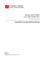
Site Address Switch–Located on the control board (S1)
For digital systems only: For the siren to report back with its identity, define the site
address by setting DIP switches located on the board. The DIP switches have values of
1, 2, 4, 8, 16, 32, 64, 128 256, 512. Add appropriate DIP switch values to define the site
number address.
Example
To define the board for Site #1, toggle the first DIP switch to the left. All other DIP switches
are to the right. For Site #2, toggle the second DIP switch to the left. For Site #3, toggle
the first and second DIP switch to the left. For Site #4, toggle the third DIP switch to the
left. For Site #5, toggle the first and third DIP switch to the left. Continue this method to
define other site number addresses.
Figure 1 Setting the Switch Number Example

16
Conguration
UltraVoice® Compact Siren/Speaker (Models RF100U and RF100H)
Federal Signal www.fedsig.com
Switch number 1 2 3 4 5 6 7 8 9 10
Binary number 1 2 4 8 16 32 64 128 256 512
Example: Switch numbers 1, 2, and 3 are binary numbers 1, 2, and 4.
Add 1 + 2 + 4 = 7; 7 is the unit address
NOTE: Programming details are in the software manual. The site address is stored at
power up of the controller. If the site address is changed, the power (battery and AC) must
be turned o and then on.
Visual Indicators
The following table provides a description of the RF100 Controller Board visual indicators.
Table 10 Visual Indicators (Located on internal control board.)
D1 CPU
D4 Relay output #1
D2 Relay output #2
D5 Relay output #3
D3 Relay output #4
D31 Relay output #5
D7 TX PTT
D10 Digital input #1
D12 Digital input #2
D19 Digital input #3
D21 Digital input #4
D11 Isolated Power Supply
D15 CARRIER - RF Carrier Indicator on with carrier present.
D23 Amplier Output Voltage
D28 Amplier Output Current
D29 DC Power
D35 and D37 Receive Level indicator,
Off when the receive level is too low.
D37 (Green) on when the receive level is correct.
D35 (Yellow) on when the receive level is too high
Radio Interface
The RF100 has a built-in radio that is programmed at the factory. If changes are required,
contact Federal Signal or a local radio shop.
Programming Functions
The RF100 can store up to fifty unique functions. Each function contains up to twenty
stacked commands. Assigning more than one command (for example, relay on, digital
message 1, 2, and 3, relay o) to each activation code or function allows you to run
a sequence of commands without sending additional activations. A complete list of
activation functions is found in the Commander® Software Reference Manual.

17
Installation
Description, Specications, Conguration, and Installation Manual
Federal Signal www.fedsig.com
Installation
Read and adhere to all safety warnings in this manual before installing the RF100.
SOUND HAZARD: The sound output of speakers is capable of causing permanent
hearing damage. Ensure people are not exposed to sounds exceeding 120 dB–
post warnings where applicable.
ELECTROCUTION HAZARD: Electrocution or severe personal injury can occur
when making electrical connections, drilling holes, or lifting equipment. Therefore,
experienced electricians, per national and local electrical codes acting under the
direction of the installation crew safety foreman, should perform the installation.
Before installing, commissioning, or performing maintenance for the RF100, visit
www.fedsig.com/warning-mass-notifications-systems-tech-support to download the ICM
checklist for the RF100.
Determine a Suitable Location
The RF100 can be mounted on any relatively flat surface with the supplied mounting
brackets. The mounting surface must be capable of supporting the weight of the speaker.
As a general rule, the warning signal SPL should be at least 10 dB above the ambient
sound level to ensure it will be heard. Speaker fidelity and placement will also aect voice
intelligibility. Review and comply with any local or state noise control ordinances as well
as OSHA noise exposure regulations and guidelines.
Many factors aect the propagation of sound through barriers, over various types of
materials, terrain, and changing weather conditions. Consult FEMA CPG1-17, CPG1-14, and
your local Federal Signal representative for assistance to place your warning equipment
properly.
Selectively turn on RF100 units and test for proper sound coverage.

18
Installation
UltraVoice® Compact Siren/Speaker (Models RF100U and RF100H)
Federal Signal www.fedsig.com
Determine the Mounting Method
The following speaker and antenna mounting options are available for the RF100.
Table 11 Speaker and Antenna Mounting Options
Mounting Options Description
Flat Wall Mount • A wall-mount bracket is included with the speaker.
• The model AMB-W antenna wall mount bracket is available
to provide a pipe mount off the surface of the wall.
Larger Pole Mount
(6-inch or larger
diameter poles)
• Use a model I-IP100-PMW to attach the speaker to the pole.
The bracket can be secured with lag bolts or stainless steel
banding.
• AMB-LP-Y bracket is for YAGI antenna mounting.
• AMB-LP-H brackets are for VHF top of pole antenna
mounting. Two brackets are included in the kit.
• AMB-LP-U bracket is for UHF top of pole antenna mounting.
• AMB-P bracket is for side pole mounting any Federal Signal
antenna.
Small Pole Mounting
(2-3/8 inch to 4-1/2 inch
diameter poles)
• Use a model I-IP100-PM to attach the speaker to the pole.
U-bolts are provided for pipe mounting.
• AMB-SP-Y bracket is for YAGI antenna mounting. U-bolts are
provided for pipe mounting.
• AMB-SP-H brackets are for VHF top of pole antenna
mounting. U-bolts are provided for pipe mounting. Two
brackets are included in the kit.
• AMB-SP-U bracket is for UHF top of pole antenna mounting.
U-bolts are provided for pipe mounting.
NOTE: Federal Signal does not recommend side pole antenna
mounting for omni-directional antennas.
Wall Mounting
The RF100 comes standard with a bracket for vertical wall or pole mount with optional
pole accessories. The standard mount can be flipped to allow ceiling mount.
To wall mount the RF100:
1. Find a suitable location to mount the speaker. Use industry or company preferred
practices when mounting hardware to structures.
2. Verify the mounting is adequate to hold the weight of the speaker, cables, and visual
devices if equipped.
3. Refer to Figure 2 or use the U-shaped wall bracket as a template to scribe the
mounting hole locations.
4. Mount the RF100 to the mounting surface with user-supplied hardware. Federal
Signal recommends 3/8-inch fasteners.
5. Loosen the pivot bolts to provide the direction of the speaker.

19
Installation
Description, Specications, Conguration, and Installation Manual
Federal Signal www.fedsig.com
Attaching the Mounting Brackets to the Speaker Housing
The RF100 comes standard with a bracket attached for vertical wall or pole mount with
optional pole accessories.
To attach the bracket to the speaker:
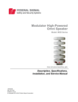
1. The mounting brackets are attached to the speaker, as shown below, using the six
supplied 1/4-20 by 5/8-inch screws.
Note the orientation of the curved slots on the L-shaped brackets; this orientation is
important for the speaker to pivot downward.
2. Tighten the 1/4-20 by 5/8-inch screws to approximately 80 in-lb.
3. Attach the U-shaped wall bracket with four supplied sets of 3/8-16 by 1-inch bolts, flat
washers, lock washers, and nuts.
Figure 2 Bracket attached to speaker
8.90
2.00
5X
.397
5.00
2.88
1.44

20
Installation
UltraVoice® Compact Siren/Speaker (Models RF100U and RF100H)
Federal Signal www.fedsig.com
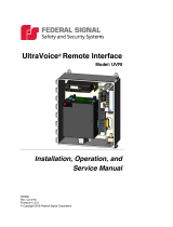
Figure 3 Depth and height with bracket
6.68
2.53
12.87
2.00 10.09
5.88
.18
Figure 4 Back view of speaker
0.74
8.10
9.97
5.22 0.16
/