Page is loading ...

Setup, Program, and User Manual
25500714
Rev. A3 1023
Printed in U.S.A.
© Copyright 2021-2023 Federal Signal Corporation
UltraVoice® Compact Siren/Speaker
Models: RF100U, RF100H, RF100HX, and RF100UX

Limited Warranty
This product is subject to and covered by a limited warranty,
a copy of which can be found at www.fedsig.com/SSG-Warranty.
A copy of this limited warranty can also be obtained by written
request to Federal Signal Corporation, 2645 Federal Signal Drive,
University Park, IL 60484, email to [email protected] or
call +1 708-534-3400.
This limited warranty is in lieu of all other warranties, express or
implied, contractual or statutory, including, but not limited to the
warranty of merchantability, warranty of tness for a particular
purpose and any warranty against failure of its essential purpose.
2645 Federal Signal Drive
University Park, Illinois 60484
www.fedsig.com
Customer Support 800-548-7229 • +1 708 534-3400
Technical Support 800-524-3021 • +1 708 534-3400
All product names or trademarks are properties of their respective owners.

3
Setup, Program, and User Manual
Federal Signal www.fedsig.com
Contents
Safety Messages......................................................................................................................................................5
General Description ................................................................................................................................................5
Introduction .........................................................................................................................................................5
RF100 Overview .................................................................................................................................................5
RF100 Setup ....................................................................................................................................................... 6
Programming the RF100 .............................................................................................................................6
1. Conguring the Radio .........................................................................................................................................8
Ritron® Radio Interface .......................................................................................................................................8
Programming Cable .................................................................................................................................... 9
Programming the Ritron® Radio ........................................................................................................................ 10
2. Assigning the Site ID .........................................................................................................................................12
Site Address Switch–Located on the control board (S1) ...................................................................................12
3. Programming the microSD Memory Card ....................................................................................................... 13
Changing the les on the microSD card ...........................................................................................................13
Digital Voice Wizard ..........................................................................................................................................13
4. Conguring Commander to Communicate with the RF100 ...........................................................................14
Mode Options ............................................................................................................................................17
5. Conguring the Encryption Key and Security Code (Optional) ....................................................................21
6. Conguring the RF100 ...................................................................................................................................... 23
Copying Functions from another RTU ......................................................................................................26
Conguring Individual RTUs .....................................................................................................................27
7. Using the Congure RTU General Parameters dialog box ............................................................................28
Initial RF100 Setup ...........................................................................................................................................28
8. Programming Functions ...................................................................................................................................34
Functions ..........................................................................................................................................................34
Naming Functions and Setting Duration and Reactivation Intervals ................................................................. 34
Activating Functions ..................................................................................................................................35
Programming Functions ............................................................................................................................36
Using the RF100 ....................................................................................................................................................41
Local Operation .................................................................................................................................................41

4
UltraVoice® Compact Siren/Speaker (Models RF100H, RF100U, RF100HX, RF100UX)
Federal Signal www.fedsig.com
Figures
Figure 1 Ritron Radio Interface Connector ........................................................................................................... 8
Figure 2 Transceiver/Programming Cable ............................................................................................................9
Figure 3 Setting the Switch Number Example .................................................................................................... 12
Tables
Table 1 Ritron Radio Interface ................................................................................................................................ 8
Table 2 Transceiver/Programming Cable ..............................................................................................................9
Table 3 Command Denitions ..............................................................................................................................38
Table 4 WAV File Messages (DV Messages) .......................................................................................................43
Table 5 Programed Functions ..............................................................................................................................44
Table 6 Programed Zones ..................................................................................................................................... 46
Table 7 Programed Activation Templates ............................................................................................................47
Table 8 Hotkeys .....................................................................................................................................................48
Table 9 Standard DV Messages ............................................................................................................................51
Radio Activation ................................................................................................................................................41
EAS Activation ..................................................................................................................................................41
DTMF and Duotone Activation ..........................................................................................................................41
Quiet Test .......................................................................................................................................................... 41
Getting Service ......................................................................................................................................................42
Appendix A Forms ................................................................................................................................................. 43
Appendix B Standard DV Messages ....................................................................................................................51

5
Safety Messages
Setup, Program, and User Manual
Federal Signal www.fedsig.com
Safety Messages
It is important to follow all instructions shipped with this product. This device is
to be installed by trained personnel who are thoroughly familiar with the country’s
electric codes and will follow these guidelines as well as local codes and
ordinances, including any state or local noise-control ordinances.
After installation, service, or maintenance, test the system to confirm that it is operating
properly. Test the system regularly to confirm that it will be operational in an emergency.
The UltraVoice® Compact Siren/Speaker (model RF100) has its own Installation Manual.
See fedsig.com for online manuals.
General Description
Introduction
This manual describes how to set up, configure, program, and use the RF100 Siren/
Speaker. See fedsig.com for other related online manuals.
This manual covers the following devices: RF100H, RF100U, RF100HX, and RF100UX; and
refers to all models as RF100.
Federal Signal RF100 units can be set up in a wide variety of networks and configurations.
This manual provides a standard setup and programming for the RF100. See the
Commander® Software Reference Manual or contact Federal Signal for special
applications using RF100 devices. “Appendix A Forms” on page 43 contains
configuration tables for documenting how your RF100 and Commander® are programmed.
RF100 Overview
The UltraVoice® Compact Siren/Speaker (model RF100) is an outdoor or indoor
RF‑enabled high‑powered speaker with an integral controller and radio. The RF100 is part
of Federal Signal’s UltraVoice series of products. Use the RF100 as a warning and alerting
device with both audible and visual indicators. The audible capabilities include locally
stored, high‑quality, high‑powered tones, pre‑recorded voice messages, and live PA. The
visual indicators include the use of strobes and lights. Equip the RF100 with up to four
local initiation devices (switches) to activate the unit locally.
The RF100 is equipped with either a VHF or UHF two‑way radio. The two‑way radio allows
for configuring the controller, activating the speaker, or polling for supervision. The radio
and controller can accept single tone, two‑tone, DTMF, EAS, and Federal Signal MSK
digital for speaker communications. Using Federal Signal MSK digital provides a secure
communications channel.
The RF100 has an internal 100‑watt amplifier/driver to deliver tone warnings and
intelligible voice messages from RF100 stored memory. The RF100 has software‑
configurable volume control for optimizing sound levels across your alerting area.
The software‑configurable volume control also includes an ambient noise monitoring
capability to automatically adjust the volume depending on external noise levels.
The RF100 is powered from either 120/240 Vac or 24 Vdc. When the RF100 is powered
from AC, there are four solid‑state relay outputs to activate AC‑powered visual alert

6
General Description
UltraVoice® Compact Siren/Speaker (Models RF100H, RF100U, RF100HX, RF100UX)
Federal Signal www.fedsig.com
devices. When the RF100 is powered from DC, there is a DC solid‑state relay output. The
RF100 has a 1/2‑inch NPT opening on the top of the speaker for simple installation of
pipe mount devices such as strobes. The bottom of the speaker has three 3/4‑inch NPT
openings to allow access to power, relay outputs, and activation inputs. The rear cover
also includes an N‑type connection for the external RF antenna. Use the Commander®
software system to configure the speaker for specific alerts and use the outputs for strobe
or visual devices.
RF100 Setup
The typical setup of an RF100 consists of programming functions for specific actions
the speaker performs. These can include voice announcements, siren tones, output
activations, and volume adjustments. Once you configure these functions, an activation
method is assigned. If the RF100 is being added to an existing system, the functions must
be coordinated with the current system design/implementation. For example, live PA
announcements are typically assigned to function 1. For new systems, Federal Signal can
assist with best practices when designing your specific system. This manual assumes the
overall design has been defined.
Programming the RF100
The following is a typical procedure for setting up and programming the RF100. Steps1
through 3 are usually completed before installing the RF100. The programming of the
RF100 requires the use of the Commander® Software System and the Ritron® radio
software. This procedure guides you through common configurations. If the speaker is to
be activated using DTMF, Duotone, or EAS, many of these steps are not required.
1. Configuring the Radio: Before installing and programming the RF100, configure the
radio to operate on your FCC‑licensed radio channel. Use the radio software to set
the frequencies and the tone or digital squelch.
2. Assigning the site ID: Before installing the RF100, the site ID is assigned. When used
with the Commander® software, you must reserve the next sequentially unique
numeric site ID numbers for use by the Commander® software to identify each siren
device. The site ID will be known as the RTU number in the Commander® software.
3. Programming the microSD Memory Card: Before installing the RF100, the microSD
memory card is programmed with digital voice or tone files required for your system.
See “Appendix B Standard DV Messages” on page 51.
4. Configuring Commander® to Communicate with the RF100: Before programming the
RF100, select your communication channel, interface type, and port. Set your Front
Porch time, determine the number of times the CCU will try to contact an RTU, and
determine how many seconds to wait between attempts.
5. Configuring the Encryption Key and Security Code (Optional): Before programming
the RF100, the Encryption Key and Security Code can be installed. Security is an
important part of any networking system. Federal Signal provides two types of
security for Commander® and the RF100s: Security Code and Encryption Keys. If
using Commander®, you can change Security Codes and Encryption Keys over the air
or by using a serial connection to the RF100.

7
General Description
Setup, Program, and User Manual
Federal Signal www.fedsig.com
6. Configuring the RF100: Using the RTU Configuration dialog box, select the unit type
as RF100, copy configurations from other units, allow Duotone or EAS, and set the
tone file used for siren tones. This dialog box also allows Commander® to download
the current programming of the RF100. Once the selections are made, Save the
selections or Quit to discard changes. If changes are made to the speaker, they must
be sent to the speaker using the Configure RTU General Parameters dialog box Send
option.
7. Use the Configure RTU General Parameters dialog box to configure general
parameters for the RF100. For example, assign the RF100 its Station Name, Station
Address, Latitude, and Longitude. Select front porch timing, assign repeater number
if being used as a repeater, reporting, security options, and channel selection.
If changes are made to the speaker, they must be sent to the speaker using the
Configure RTU General Parameters dialog box Send option.
8. Programming Functions: Use the Program dialog box to create program functions,
assign inputs to activate functions at the speaker, assign DTMF codes for over‑the‑air
activations, assign Duotone frequencies or EAS Events to specific functions.
The following pages detail the dialog boxes and descriptions of the RF100 options.

8
1. Conguring the Radio
UltraVoice® Compact Siren/Speaker (Models RF100H, RF100U, RF100HX, RF100UX)
Federal Signal www.fedsig.com
1. Conguring the Radio
Before installing and programming the RF100, configure the radio to operate on your
FCC‑licensed radio channel. Use the radio software to set the frequencies and the tone
or digital squelch. See the “Programming the Ritron® Radio” on page 10 for more
information.
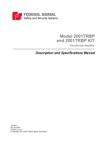
Ritron® Radio Interface
The following picture illustrates the Ritron® Radio Interface connector.
Figure 1 Ritron Radio Interface Connector
The following table describes the functions of each pin.
Table 1 Ritron Radio Interface
Pin # Function
1Least signicant channel select bit (CS0)
2 Channel select 1 (CS1)
3Most signicant channel select (CS2)
Binary 4, 2, and 1. All open = channel 8 (7 binary).
4 Microphone input
5 High/low power select (pull low to get low power)
6 + 9 to 17 Vdc input
7 Auxiliary input, 8-2500 Hz, 1.5/3.0 kHz deviation with 300 mVP-P
8Auxiliary output, >/= 600 Ω, 12 to 2500 Hz, 1 VP-P for 1.5/3.0 kHz deviation
9 PC programming port, single wire TXD/RXD, 3-5 V, 2400 baud, not inverted,
start bit low
10 Volume control (RSSI option)
11 Auxiliary monitor input (pull to ground to open squelch). Can be used for tone
detect.
12 Speaker output
13 Carrier detect output (pulls to 3.3 Vdc through internal 390 Ω)
14 PTT (pull to ground to transmit), with time-out-timer
15 Ground

9
1. Conguring the Radio
Setup, Program, and User Manual
Federal Signal www.fedsig.com
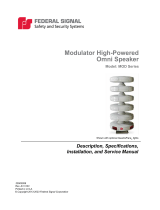
Programming Cable
Figure 2 Transceiver/Programming Cable
Table 2 Transceiver/Programming Cable
Ritron® DB15 Controller RJ45 Programming RJ25
6, +12 V Power 5 and 7, +12 V power
7, Auxiliary input 2, TX Audio
9, Serial Data 3 and 4
12, Speaker Audio 1, RX Audio
13, Carrier detect 3, Carrier Detect
14, PTT 4, PTT
15, GND 6 and 8, GND 1, GND

10
1. Conguring the Radio
UltraVoice® Compact Siren/Speaker (Models RF100H, RF100U, RF100HX, RF100UX)
Federal Signal www.fedsig.com
Programming the Ritron® Radio
Before installing and programming the RF100, configure the radio to operate on your
FCC‑licensed radio channel. A programming software kit is required to program the radio
(part number Q19902536A). The kit includes programming software and a USB interface
cable. Once the software is installed, check for a DTX LS update at
https://www.ritron.com/tech. Connect the radio to your computer with the Ritron®
9/USB‑PAS USB programming cable. Use the radio software to set the frequencies and
the tone or digital squelch.
To program the Ritron® radio:
1. Install the Ritron® radio software.
2. Connect the Ritron® radio with the 9/USB‑PAS programming cable.
3. From your computer, start the software and select the proper Com port.
4. Select your model name or read the radio.
5. Type your Customer ID.
6. Select channel 8 and click the Edit button or double‑click channel 8. The Channel8
dialog box appears. Here you can set the frequencies and the tone (QC) or digital
(DQC) squelch if used.

11
1. Conguring the Radio
Setup, Program, and User Manual
Federal Signal www.fedsig.com
To delete a channel, select the channel and click the Delete button or right‑click the
channel and select Delete.
7. Click Radio > Program Radio.
8. Click Edit > Tune Radio.
9. Click the User Setup button and select the RX Auxiliary Out Gain option on the Tune
button.
10. Use the slider to set the level to 7, and then click the Save button.

12
2. Assigning the Site ID
UltraVoice® Compact Siren/Speaker (Models RF100H, RF100U, RF100HX, RF100UX)
Federal Signal www.fedsig.com
2. Assigning the Site ID
When used with the Commander® software, you must reserve the next sequentially
unique numeric site ID numbers for use by the Commander® software to identify each
siren device. The site ID is the RTU number in the Commander® software.
Do not duplicate IP addresses or site ID numbers on the network at any time, or
network errors occur. The Siren Site ID numbers start at number 001 and are numbered
sequentially. Commander® Control Station Site ID numbers start at number 900.
Site Address Switch–Located on the control board (S1)
For digital systems only: For the siren to report back with its identity, define the site
address by setting DIP switches located on the board. The DIP switches have values of
1, 2, 4, 8, 16, 32, 64, 128 256, 512. Add appropriate DIP switch values to define the site
number address.
Example
To define the board for Site #1, toggle the first DIP switch to the left. All other DIP switches
are to the right. For Site #2, toggle the second DIP switch to the left. For Site #3, toggle
the first and second DIP switch to the left. For Site #4, toggle the third DIP switch to the
left. For Site #5, toggle the first and third DIP switch to the left. Continue this method to
define other site number addresses.
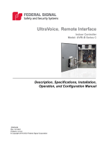
TIP: Sliding the DIP switch towards the number printed on the circuit board enables that
number value.
Figure 3 Setting the Switch Number Example
Switch number 1 2 3 4 5 6 7 8 9 10
Binary number 1 2 4 8 16 32 64 128 256 512

13
3. Programming the microSD Memory Card
Setup, Program, and User Manual
Federal Signal www.fedsig.com
Example: Switch numbers 1, 2, and 3 are binary numbers 1, 2, and 4.
Add 1 + 2 + 4 = 7; 7 is the unit address
NOTE: Programming details are in the software manual. The site address is stored at
power up of the controller. If the site address is changed, the power (battery and AC) must
be turned o and then on.
3. Programming the microSD Memory Card
The RF100 control board includes a microSD card capable of storing over 4,000 voice or
tone messages that total up to 17 hours of total recording time.
The digital voice message file format is 8000 samples per second, 8 bit, mono. Siren
sounds, horn sounds, and music should be at no more than 90% of the maximum level
(‑1dB) to prevent them from overdriving the amplifier and overpowering the drivers. These
can be normalized to set them at the maximum level and then reduced to 90% or ‑1 dB.
This will deliver full nominal output power.
Save these messages with a DV#.wav naming format, or the messages are not
recognized. This naming format results in messages DV1.wav through DV4093.wav.
Federal Signal recommends using the Digital Voice Wizard.
Changing the les on the microSD card
The RF100 comes from the factory with a standard set of voice and tone files loaded on
the microSD card. Federal Signal can provide custom or standard voice messages.
To change the files on the microSD card:
1. Remove the microSD card from JP10.
2. Use a PC to change, add, or delete files.
3. Reinsert the microSD card back into JP10 before closing the RF100.
You need to filter the files to reduce content below 300 Hz. This prevents low‑frequency
tones in a recording from saturating the output transformer and the speaker drivers.
SPEAKER DAMAGE: The speaker drivers cannot reproduce these frequencies and
can be damaged by them.
Digital Voice Wizard
Loading voice or tone files onto the microSD card requires a PC and proper file naming.
Use the Digital Voice Wizard to load and name files onto a microSD card correctly.

14
4. Conguring Commander to Communicate with the RF100
UltraVoice® Compact Siren/Speaker (Models RF100H, RF100U, RF100HX, RF100UX)
Federal Signal www.fedsig.com
4. Conguring Commander to Communicate with the RF100
Use the following procedure to configure Commander® to communicate with the RF100.
Each of these options is detailed in this section with descriptions.
To configure Commander:
1. Start the Commander® application. From the Commander® main window, click System
Setup.
The System Setup dialog box appears.
2. In the Channel box, select your communication channel.
3. In the Mode list, select the type of communication interface Commander® uses to
communicate with the sirens on the respective channel.
4. In the Comm Port, select your communication port.
5. If you selected the SS2000+ or Modem Modes, the FSK and DTMF Duotone check
boxes appear. Select the FSK check box to communicate with siren sites digitally.
(Most systems use this option.) Select the DTMF Duotone check box to transmit
DTMF or Duotone codes.
NOTE: The DTMF Duotone selection will not allow programming or configuration
changes of the RF100; therefore, it should not be selected until all system
programming is completed in the FSK mode. Once the configuration is complete, the
DTMF Duotone feature can be enabled as needed.
6. If you selected the Serial Mode, the Baud Rate option appears. Select this option to
allows direct communication to sirens or other RS‑232 devices.
7. In the Front Porch box, type your front porch time. This option is only available with
the Modem Mode.

15
4. Conguring Commander to Communicate with the RF100
Setup, Program, and User Manual
Federal Signal www.fedsig.com
NOTE: Typical radio systems perform optimally with a Front Porch time of 500 ms.
Increase or decrease values according to the nature of the radio system being used.
8. In Polling Mode, select Sequential or Broadcast. If this control is unavailable, accept
the default value. Most systems will use Sequential Mode. The Broadcast mode is
only available with SmartMsg, TCP, UDP, FSModem‑Cellbase, SkyWave IDP, AtHoc,
Tetra1, and Tetra2.
Sequential Mode polls units one at a time sequentially. Broadcast Mode polls all units
at the same time.
When Broadcast mode is used, the Retry Delay must be long enough to ensure all
RTUs have time to respond. Typical values are 120 seconds with a Skywave IDP
channel and 15 seconds without a Skywave IDP channel. NOTE: Broadcast mode may
only be used on channels that allow multiple devices to communicate on a channel at
the same time, for example, satellite and IP channels.
NOTE: Sequential Mode is required for all systems except the IP/TCP systems and
any other communications method that requires Sequential Transmission to be
enabled.
9. In the #Tries list, select the number of times the CCU will contact an RTU before
considering the communication attempt to be a Comm Fail.
10. In the Retry Delay box, type how many seconds to wait between attempts to contact
an RTU.
NOTE: Set the Retry Delay to a value longer than the time required to poll a single
RTU. This allows Commander® to wait a sucient amount of time before attempting a
retry. A value between 5 and 7 seconds is optimal for a typical radio system.
11. Select the Repeat All Call 3 times to send All Call and Zone activation transmissions
three times.
12. In the CCU Addr, type the unique identifier for the Commander® site.
13. Click Save.
Review the following table for more information about the fields on the System Setup
dialog box in the Communication panel.
Fields Description
Channel Commander® supports up to four communication channels. Each
channel is assigned a Mode and Com Port number (if applicable).
Using multiple channels allows Commander® to support multiple
communication modes. It is important to remember the following
limitations when using multiple channels:
• The Com Port setting must be unique for all channels using an
RS232 serial port.
• All congured channels are used in parallel as opposed to a primary
channel with failover implementation.

16
4. Conguring Commander to Communicate with the RF100
UltraVoice® Compact Siren/Speaker (Models RF100H, RF100U, RF100HX, RF100UX)
Federal Signal www.fedsig.com
Fields Description
Mode Selects the type of communication interface Commander® uses to
communicate with the sirens on the respective channel. See “Mode
Options” on page 17 for more details.
The following features are dependent on the Mode selection:
• PA (VOIP): Only available when Mode is SmartMsg, Modem, or
SS2000+
• DTMF and Duotone Encode: Only available for SS2000+ and
Modem
Click the Mode arrow to see options.
Com Port The Communication Port is available for modes using a USB or RS232
serial port. Only ports currently available on your system are available
for selection.
Front Porch Front Porch is the amount of time when the PTT is asserted, and the
analog or data starts streaming. The time gives the transmitting radio
time for the transmitter to come up to full power and the receiving radio
time to detect the signal and start receiving before the analog or data
starts.
To set your front porch: enter a value between 0-10000 milliseconds.
Most conventional radio systems will require a front porch between 300-
1000 ms depending on the model transceiver employed. For systems
using the SS2000+, the front porch is set by the SS2000+, and this
parameter is ignored.
Polling Mode Determines how the units are polled when a Poll All is initiated. Select
either Sequential or Broadcast for each channel used.
Select Sequential Mode to poll each RTU one at a time in numerical
order. Sequential polling is required for conventional radio networks
and serial data channels that do not allow more than one device to
communicate on the channel at the same time.
Select Broadcast Mode to issue a single All Call poll request to all
RTUs at the same time. Broadcast polling is faster and more efcient
because it reduces the total amount of trafc on the channel. Verify the
communication channel can support the amount of trafc generated by
simultaneous channel use before enabling Broadcast Mode.
If both Sequential and Broadcast channels are enabled, the Broadcast is
sent rst, followed by sequential transmissions to each site. Sequential
and Broadcast each have their own Number of Tries and Retry Delay
parameters. For Broadcast mode, the Retry Delay must be long enough
for all sites to report in. Dynamic Zoning must be enabled to allow
polling retry attempts to occur on a Broadcast channel.
When both polling modes are used with an RTU, COM fails will not be
logged until all retries and retry delays have ended.
# Tries Determines how many times the CCU will try to contact an RTU before
considering the communication attempt to be a Comm Fail. The CCU
will wait between tries the number of seconds indicated by the Retry
Delay.

17
4. Conguring Commander to Communicate with the RF100
Setup, Program, and User Manual
Federal Signal www.fedsig.com
Fields Description
Relay Delay Determines how many seconds to wait between attempts to contact an
RTU.
Set the retry delay to a value longer than the time required to poll a
single RTU. This value will vary depending on the communication
channel and equipment employed. A value between 5 and 10 seconds is
optimal for a typical conventional radio system.
Repeat All Call 3
times
When checked, All Call and Zone activation transmissions are sent three
times. When unchecked, All Call and Zone transmissions are sent once.
Typically this should be checked to decrease the likelihood of noise
on the channel causing a missed activation. If multiple transmissions
are causing a problem with live PA, disable this feature. It may also
be necessary to disable this feature when all call repeaters are used if
there is not enough time between repeats for the repeat sequence to
complete.
NOTE: This setting does not affect programmable HotKeys. HotKeys
have their own Repeat All Call 3 Times setting, which may be
independently congured for each HotKey.
Interval Type the repeat Interval in seconds. This eld applies even if Repeat
All Call 3 times is unavailable because HotKeys can be congured to
Repeat as well.
Security Keys Click the Security Keys button to open the Security Keys dialog box to
view or modify the keysets used to encrypt communication.
Mode Options
These types of communication interfaces are available for the Mode option.
Disabled
Select Disabled to disable mode.
SS2000
Select when interfacing to the Federal Signal SS2000 console. The Com Port option
becomes available.
SS2000+
Select when interfacing to the Federal Signal SS2000+ using an RS232 connection.
Select an active serial Comm port from the drop‑down menu. The connection status of
the SS2000+ is monitored on the SS status bar at the bottom of the screen.
The following check boxes appear:
• FSK: Click to communicate with siren sites digitally. (Most systems use this option.)
• DTMF Duotone: Click if the SS2000+ is used to transmit DTMF or Duotone codes.

18
4. Conguring Commander to Communicate with the RF100
UltraVoice® Compact Siren/Speaker (Models RF100H, RF100U, RF100HX, RF100UX)
Federal Signal www.fedsig.com
SS2000+ IP
Select the SS2000+ IP mode to connect to the SS2000+ using a LAN connection instead
of an RS232 connection. This mode communicates through a SmartMsg communications
service using port 16887 and does not support live streaming audio (PA‑VOIP/PA‑WAV).
You must enter the SS2000+ CCU Address to use this mode. The connection status of the
SS2000+ is monitored on the SS status bar at the bottom of the screen.
Modem
Select when interfacing to the Federal Signal model MODEM‑MSK. The Comm Port and
Front Porch options becomes available.
The following check boxes appear:
• FSK: Click to communicate with siren sites digitally. (Most systems use this option.)
• DTMF Duotone: Click if the modem is used to transmit DTMF or Duotone codes.
SmartMsg
Select SmartMsg when communicating to sirens on the Federal Signal SmartMsg platform.
When SmartMsg mode is selected, the root SmartMsg server must be specified in the
SmartMsg Server panel on the System Setup dialog box.

19
4. Conguring Commander to Communicate with the RF100
Setup, Program, and User Manual
Federal Signal www.fedsig.com
TCP and UDP
Select TCP to communicate with IP‑enabled RTUs. This mode requires the RTU to be
equipped with a device or module enabling network connectivity such as a Cellular
modem. Use UDP mode to interface with Motorola P25 trunked radio networks.
Configure Commander® and the RTU correctly for successful TCP mode communication.
TCP mode requires the configuration of the following parameters:
• TCP Port (System Setup): The TCP Port Commander® will use to listen for incoming
connections.
• IP:Port (Configure RTU General Parameters): The IP Address and Port Commander®
will use to initiate the connection with the RTU.
RTU TCP interface
The configuration of the RTU interface unit will vary depending on the device used. Below
is a list of general guidelines for configuring a TCP/IP device.
• Configure the device for TCP/IP communication.
• Set the Destination or Auto Connect IP Address to the IP Address of the Commander®
computer.
• Set the Destination or Auto Connect Port number to the TCP Port configured on the
Commander® System Setup screen channel.
• Set the Device listening port number. This is the port Commander® will use to initiate
a connection to the device and must match the Commander® Configure RTU General
Parameters setting for the RTU.
• Configure the device RS232 settings: 9600,N,8,1 no handshaking.
• Check network and PC firewall settings. Allow incoming connections on the specified
port and any ports used for the configuration of the device.

20
5. Conguring the Encryption Key and Security Code (Optional)
UltraVoice® Compact Siren/Speaker (Models RF100H, RF100U, RF100HX, RF100UX)
Federal Signal www.fedsig.com
Serial
Select to allow direct communication to sirens or other RS‑232 devices such as
MOTOTRBO and RF modems. Serial mode requires the selection of a Comm Port and
Baud Rate. For direct serial communication to sirens, set the baud rate to 1200 or 9600
depending on Unit Type and configuration.
FSModem-Cellbase
The interface uses a USB or RS232 connection and requires the communications port to
be selected from the drop‑down menu. The connection status of the FSModem‑Cellbase
is shown on the status bar at the bottom of the screen.
SkyWave IDP
NOTE: SkyWave is obsolete.
Select SkyWave IDP for interfacing to SkyWave satellite terminals. SkyWave IDP mode
requires the configuration of additional parameters on the SkyWave Setup dialog box
accessed from the System Setup menu bar. In addition, each RTU must be assigned
the associated SkyWave Terminal ID number on the Configure RTU General Parameters
dialog box. See the Commander® Software Reference Manual, 25500646, for more
details.
AtHoc (optional)
The AtHoc mode enables a custom peripheral serial interface.
Tetra1 and Tetra2 (optional)
The Tetra modes are designed to be used with systems communicating on a Tetra
trunked radio infrastructure.
• Tetra1 = TMRI‑880i radio
• Tetra2 = Motorola MTM‑5400 and Supra
/