Page is loading ...

25500444
Rev. A0 0118
Printed in U.S.A.
© Copyright 2018 Federal Signal Corporation
UltraVoice
®
Remote Interface
Model: UVRI-B
Description, Specications,
and Installation Manual

Limited Warranty
This product is subject to and covered by a limited warranty,
a copy of which may be found at www.fedsig.com/SSG-Warranty.
A copy of this limited warranty may also be obtained by written
request to Federal Signal Corporation, 2645 Federal Signal Drive,
University Park, IL 60484; by email to [email protected], or
by calling +1 708 534-3400.
This limited warranty is in lieu of all other warranties, express or
implied, contractual or statutory, including, but not limited to the
warranty of merchantability, warranty of tness for a particular
purpose and any warranty against failure of its essential purpose.
2645 Federal Signal Drive
University Park, Illinois 60484-3617
www.fedsig.com
Customer Support 800-548-7229 • +1 708 534-3400
Technical Support 800-524-3021 • +1 708 534-3400
All other product names or trademarks are properties of their respective owners.
All products indicated are trademarks of Federal Signal Corporation.

3
Description, Specications, and Installation Manual
Contents
Safety Messages......................................................................................................................................................8
General Description ..............................................................................................................................................10
Introduction .......................................................................................................................................................10
Overview ...........................................................................................................................................................10
Models Description ................................................................................................................................... 11
Features ............................................................................................................................................................ 11
Communications Link ........................................................................................................................................12
Unit Type ................................................................................................................................................... 12
RF Frequency ...........................................................................................................................................13
Security Key ..............................................................................................................................................13
128-bit/256-bit Encryption Key ..................................................................................................................13
Unit Address ..............................................................................................................................................13
User Programs .................................................................................................................................................. 14
Status Monitoring ..............................................................................................................................................14
Specications ........................................................................................................................................................14
Connectors, Conguration Jumpers, Test Points, Controls and Indicators ....................................................... 17
Conguration Jumpers ..............................................................................................................................22
Indicators ..................................................................................................................................................24
POT Settings .............................................................................................................................................25
Environmental and Physical ......................................................................................................................25
Software Tests ..........................................................................................................................................25
Conguring ........................................................................................................................................................26
Installation ..............................................................................................................................................................26
Control Unit Location ........................................................................................................................................26
General Mounting Guidelines ...........................................................................................................................31
UVRI-B Installation Material List and Installation Guidelines ............................................................................31
Concrete or Filled Cement Block Wall Mounting Guidelines ....................................................................31
Hollow Block Wall Mounting Guidelines ....................................................................................................32
Wood Stud Wall Mounting Guidelines.......................................................................................................32
Metal Stud Wall Mounting Guidelines .......................................................................................................32
Electrical Connections ......................................................................................................................................34
Grounding Requirements ..........................................................................................................................34

4
UltraVoice Remote Interface (UVRI-B)
Wiring Guidelines for 120 Vac Electrical Service ..................................................................................... 34
Wiring Guidelines for 240 Vac Electrical Service ..................................................................................... 35
Connecting Audio Output .......................................................................................................................... 35
Relay Output .............................................................................................................................................35
Ethernet Connection .................................................................................................................................35
Battery Connections ..................................................................................................................................35
Speaker Connections (JP2 on the Amplier board) ..........................................................................................36
Local PA Audio Connections (J1 on the UVRI-B Control board) ....................................................................... 36
Remote Activation Contact Closure Inputs (JP22 on the UVRI-B Control board) .............................................36
Optional External 24 VDC Power Connections (JP23 on the UVRI-B Control board) ......................................36
600 Ohm I/O Connections (JP8 on the UVRI-B Control board) ........................................................................ 37
Control Connections .................................................................................................................................37
Audio Connections ....................................................................................................................................37
Turning on the Power ........................................................................................................................................37
Installing the Antenna ...........................................................................................................................................38
Installing the Cabinet Mounted Magnetic Base Antenna ..........................................................................38
Installing the Remote Mounted Magnetic Base Antenna ..........................................................................38
Installing the Yagi Antenna ........................................................................................................................38
Installing the Omni Fiberglass Antenna Models ........................................................................................41
Pre-operational System Conguration and Testing ...........................................................................................43
Visual Inspection ...............................................................................................................................................43
Amplier and Speaker Pre-Operation Checkout ............................................................................................... 43
Adjusting the Radio Transceiver (if applicable) ................................................................................................. 43
Control and Status Monitoring ..........................................................................................................................44
Operations..............................................................................................................................................................45
Manual Activation .............................................................................................................................................. 45
Local Public Address .........................................................................................................................................45
Relay Output .....................................................................................................................................................46
Sensor Inputs .................................................................................................................................................... 46
Status Monitoring ..............................................................................................................................................46
Quiet Test .......................................................................................................................................................... 47
AC/DC Power System .......................................................................................................................................47
Applications ...........................................................................................................................................................47

5
Description, Specications, and Installation Manual
Two-Way Radio Controlled System ..................................................................................................................47
Fire Panel Interface ...........................................................................................................................................47
Fiber-connected Facility .................................................................................................................................... 47
Maintenance ...........................................................................................................................................................48
Control Unit Preventive Maintenance ...............................................................................................................48
General Maintenance ........................................................................................................................................48
Checking Signal Operational ....................................................................................................................48
Checking the Battery .................................................................................................................................49
Replacing the Battery ................................................................................................................................49
Troubleshooting ....................................................................................................................................................49
Replacement Parts ................................................................................................................................................50
Getting Service ......................................................................................................................................................50
Appendix A UVRI-B Field Service Data Sheet .....................................................................................................51

6
UltraVoice Remote Interface (UVRI-B)
Tables
Table 1 UVRI-B Models .......................................................................................................................................... 11
Table 2 Electrical on the Control Board ..............................................................................................................14
Table 3 Electrical on the Amplier Board ............................................................................................................ 14
Table 4 Serial and I
2
C Ports on Control Board ....................................................................................................15
Table 5 Relay Outputs on Control Board ............................................................................................................15
Table 6 600 ohm I/O Balanced Line on Control Board ....................................................................................... 15
Table 7 Audio Outputs on Control Board ............................................................................................................15
Table 8 Audio Sense Input on Control Board .....................................................................................................15
Table 9 Remote Activation and Sensor Inputs on Control Board .....................................................................15
Table 10 TC1 Relay Outputs on Control Board ...................................................................................................15
Table 11 TC1 Sensing Inputs on Control Board .................................................................................................16
Table 12 Signaling Formats ..................................................................................................................................16
Table 13 Connectors on the Control Board (See Figure 2) ................................................................................17
Table 14 Connectors on the Amplier board (See Figure 2) .............................................................................22
Table 15 Conguration Jumpers on the Control Board (See Figure 3) ............................................................ 22
Table 16 Conguration Jumpers on the Amplier board ...................................................................................23
Table 17 Control Board Controls: Addressing, Local Activation, and Adjustments (See Figure 3) .............. 23
Table 18 Indicators on the Control Board (See Figure 3) ..................................................................................24
Table 19 Indicators on the Amplier board .........................................................................................................24
Table 20 POT Settings on the Control board ......................................................................................................25
Table 21 POT Settings on the Amplier board ....................................................................................................25
Table 22 Environmental and Physical .................................................................................................................25
Table 23 Software Tests ........................................................................................................................................25
Table 24 Concrete or Filled Cement Block Wall Mounting Materials ................................................................ 31
Table 25 Hollow Block Wall Mounting Materials ................................................................................................. 32
Table 26 Wood Stud Wall Mounting Materials ....................................................................................................32

7
Description, Specications, and Installation Manual
Table 27 Metal Stud Wall Mounting Materials .....................................................................................................32
Table 28 Installer Supplied UVRI-B Electrical Installation Material List ........................................................... 33
Table 29 Manual Activation Buttons on Control Board ......................................................................................45
Table 30 Sensor Connections ..............................................................................................................................46
Table 31 Troubleshooting .....................................................................................................................................49
Table 32 Replacement Part Numbers ..................................................................................................................50
Figures
Figure 1 UVRI-B Parts Layout ..............................................................................................................................10
Figure 2 UVRI-B Boards (Lines A, B, C for Control Board to Amplier Connection) ......................................20
Figure 3 Control Board with Conguration Jumpers, Controls, and indicators .............................................21
Figure 4 Typical UVRI-B Installation Drawing (Fire Panel Interface) ................................................................27
Figure 5 UVRI-B Cabinet Dimensional - Front and Side View ...........................................................................28
Figure 6 UVRI-B Cabinet Dimensional - Back View ............................................................................................29
Figure 7 UVRI-B Drawing of system ....................................................................................................................30
Figure 8 Yagi Antenna Installation Example .......................................................................................................41
Figure 9 Omni Antenna Installation Example .....................................................................................................42
Figure 10 Antenna Grounding .............................................................................................................................. 42
Figure 11 UVRI-B Activation Buttons ..................................................................................................................45

8
Safety Messages
UltraVoice Remote Interface (UVRI-B)
Safety Messages
It is important to follow all instructions shipped with this product. This device
is to be installed by trained personnel who are thoroughly familiar with the
country electric codes and will follow these guidelines as well as local codes.
Listed below are important safety instructions and precautions you should follow:
Important Notice
Federal Signal reserves the right to make changes to devices and specications detailed in
the manual at any time in order to improve reliability, function or design. The information
in this manual has been carefully checked and is believed to be accurate; however, no
responsibility is assumed for any inaccuracies.
Publications
Federal Signal recommends the following publications from the Federal Emergency
Management Agency for assistance with planning an outdoor warning system:
• The “Outdoor Warning Guide” (CPG 1-17)
• “Civil Preparedness, Principles of Warning” (CPG 1-14)
• FEMA-REP-1, Appendix 3 (Nuclear Plant Guideline)
• FEMA-REP-10 (Nuclear Plant Guideline).
Planning
• If suitable warning equipment is not selected, the installation site for the siren is
not selected properly or the siren is not installed properly, it may not produce the
intended optimum audible warning. Follow Federal Emergency Management Agency
(FEMA) recommendations.
• If sirens are not activated in a timely manner when an emergency condition
exists, they cannot provide the intended audible warning. It is imperative that
knowledgeable people, who are provided with the necessary information, are
available at all times to authorize the activation of the sirens.
• When sirens are used out of doors, people indoors may not be able to hear the
warning signals. Separate warning devices or procedures may be needed to
effectively warn people indoors.
• The sound output of sirens is capable of causing permanent hearing damage. To
prevent excessive exposure, carefully plan siren placement, post warnings, and
restrict access to areas near sirens.
• Activating the sirens may not result in people taking the desired actions if those to
be warned are not properly trained about the meaning of siren sounds. Siren users
should follow FEMA recommendations and instruct those to be warned of correct
actions to be taken.

9
Safety Messages
Description, Specications, and Installation Manual
• After installation, service, or maintenance, test the siren system to conrm that it is
operating properly. Test the system regularly to conrm that it will be operational in
an emergency.
• If future service and operating personnel do not have these instructions to refer to,
the siren system may not provide the intended audible warning and service personnel
may be exposed to death, permanent hearing loss, or other bodily injury. File these
instructions in a safe place and refer to them periodically. Give a copy of these
instructions to new recruits and trainees. Also give a copy to anyone who is going to
service or repair the siren.
Installation and Service
• Electrocution or severe personal injury can occur when performing various
installation and service functions such as making electrical connections, drilling
holes, or lifting equipment. Therefore only experienced electricians should install
this product in accordance with national, state and any other electrical codes having
jurisdiction. Perform all work under the direction of the installation or service crew
safety foreman.
• The sound output of sirens is capable of causing permanent hearing damage. To
prevent excessive exposure, carefully plan siren placement, post warnings and
restrict access to areas near the sirens. Sirens may be operated from remote control
points. Whenever possible, disconnect all siren power including batteries before
working near the siren.
• After installation or service, test the siren system to conrm that it is operating
properly. Test the system regularly to conrm that it will be operational in an
emergency.
• If future service personnel do not have these warnings and all other instructions
shipped with the equipment to refer to, the siren system may not provide the intended
audible warning and service personnel may be exposed to death, permanent hearing
loss, or other bodily injury. File these instructions in a safe place and refer to them
periodically. Give a copy of these instructions to new recruits and trainees. Also, give
a copy to anyone who is going to service or repair the sirens.
Operation
Failure to understand the capabilities and limitations of your siren system could result in
permanent hearing loss, other serious injuries or death to persons too close to the sirens
when you activate them or to those you need to warn. Carefully read and thoroughly
understand all safety notices in this manual and all operations-related-items in all
instruction manuals shipped with equipment. Thoroughly discuss all contingency plans
with those responsible for warning people in your community, company, or jurisdiction.
Read and understand the information contained in this manual before
attempting to install or service the siren.
Pay careful attention to notices located on the equipment.

10
General Description
UltraVoice Remote Interface (UVRI-B)
General Description
Introduction
The UltraVoice Remote Interface unit (UVRI-B) provides remote extension of Federal
Signal indoor and outdoor warning systems. The UVRI-B is available with a number
of standard and optional features to allow efcient and cost-effective alerting and
notication.
The UVRI-B is available for indoor applications only.
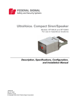
Figure 1 UVRI-B Parts Layout
INTRUSION
SWITCH
FAULT
INDICATOR
TYPE N - FEMALE
ANTENNA CONNECTOR
TRANSCEIVER
(OPTIONAL)
SPEAKER
AC POWER
INPUT
AMPLIFIER
AUDIO OUTPUT
RELAY
CONNECTIONS
BATTERY
POWER
DISCONNECT
RADIO
POWER
DISCONNECT
12VDC BATTERY
1/2" CONDUIT
KNOCKOUTS
AUDIO
AMPLIFIER
PCBA
CONTROL
PCBA
MICROPHONE
CLIP (OPTIONAL)
Overview
All relay control, audio generation, and remote communication functions are handled by
the UVRI-B control board. The control board contains connectors and terminal blocks for
interconnection to other system components.
The UVRI-B receives remote control signals and responds to the Federal Signal
Commander System for live PA and for activation of recorded voice, warning tones,
and relay outputs. The UVRI-B can provide a relay contact closure and audio output for
interfacing local re panel notication.

11
General Description
Description, Specications, and Installation Manual
Operation is supervised and status information is transferred back to the control station(s)
through one or more available communications networks. The UVRI-B monitors the
audio output level and the Remote Activation input to verify proper operation. Remote
Fire Alarm and PA systems provide a contact closure to indicate proper operation.
The control board is powered from 120 or 240 Vac with 12 Vdc battery backup. The
UVRI-B can also be optionally congured for 24 Vdc operation.
Models Description
All UVRI-B models are designed for two-way control and status monitoring using the
Federal Signal Commander System. All models can be equipped with a micro-SD card
for local storage of voice and/or tone messages.
Table 1 UVRI-B Models
Model Description
UVRI-B IP enabled, battery backup
UVRI-BH IP enabled, battery backup, VHF radio
UVRI-BU IP enabled, battery backup, UHF radio
UVRI-B100 IP enabled, battery backup, 100 watt amplier
UVRI-BH100 IP enabled, battery backup, VHF radio with 100 watt amplier
UVRI-BU100 IP enabled, battery backup, UHF radio with 100 watt amplier
Features
The UVRI-B unit has the following features.
• 120/240 Vac operation (Optional 24 Vdc Operation)
• Built-in battery charger (12 Vdc)
• IP-enabled standard
• Mass storage for digital voice messages
• Built-in standard warning tones: wail, alternate wail, pulsed wail, steady, alternate
steady, pulsed steady, and Westminster chime (auxiliary)
• Standard models with VHF and UHF radio communications
• Standard models with 100 W amplier
• Local microphone input and volume control for public address requires microphone
MNC-MC
• Local pushbuttons (eight) for activations (or for cabinet-mounted switches use
OMRON® A22NN-XXM or equivalent momentary switch)
• Enclosure mounted speaker
• Relays for activation of local hardware (for example, strobes)
• Battery backup during loss of power events (12 Ah battery included)

12
General Description
UltraVoice Remote Interface (UVRI-B)
• Remote download for voice message downloads using IP interface
• Remote monitoring of system and speaker circuits
• Optional cellular, satellite, or broadband IP communications
• Stackable siren functions enable user pre-dened warning scenarios
• 600 ohm I/O for wire line control and status monitoring
• 600 ohm input/output for connection to external ampliers and re protection systems
• Built-in 8 ohm (0.7 W) Audio Output. Typically used for cabinet speaker.
• Built-in 10 V/25 V (0.7 W) Audio Output. Typically used to interface 100 W optional
amplier.
• Monitoring and control of standard amplier for voltage, current, and status
• Two transceiver ports for radio communications
• Built-in level meter to set and monitor receive level for radio interface
• VOX to provide carrier detect for primary transceiver port
• Optional noise monitoring for automatic level control
• Real-time battery voltage monitoring
• Ambient noise level monitoring with automatic volume control requires microphone
X-SM1-FS1
• Supervised and fault monitored TC1/TC2 Fire Alarm Panel Interface
• Local Audible and Visible Trouble Indicators
Communications Link
When the UVRI-B is equipped with a communications interface, the following interface
parameters require conguration:
1. Unit Type
2. RF Frequency
3. Security Key
4. 128/256-bit Encryption Key
5. Unit Address
6. Conguration Jumper Settings
Unit Type
The Federal Signal Commander System requires conguration based on the
communications method. See the Commander Software Manual for conguration
information.

13
General Description
Description, Specications, and Installation Manual
RF Frequency
Program the radio transceiver with the RF frequency(s), channel spacing and power
output before placing into service. These settings are pre-set at the factory if the
requirements are provided with the order.
Security Key
The Security Key is a unique number assigned to the system that prevents interference of
nearby systems operating on the same RF frequency. Like the 128-bit/256-bit encryption
key, the Security Key is typically programmed during initial system programming. All
sites in the system must use the same security key. The exception is a key value of 65535
(the default), dened as an open system and communicates with all encoders regardless
of the encoder’s key setting.
128-bit/256-bit Encryption Key
The 128-bit or 256-bit data encryption provides security against malicious operation
or monitoring. Program the 128-bit/256-bit encryption key during the ashing of
the microprocessor to match the encoder (Federal Signal Commander Software or
SS2000+) being used to activate the unit. A key value of zero disables the 128-bit/256-bit
encryption; use if the encoder does not support 128-bit/256-bit encryption. All sites in the
system must use the same encryption key.
Unit Address
The unit address sets the UVRI-B site number and is used to numerically identify the
site within the system network. The unit address is a three-digit number with a range of
001 to 1023. The unit address is set using dip switch S1. S1 off position indicates active
position. Add binary active switch positions to get ID address
Switch number 1 2 3 4 5 6 7 8 9 10
Binary number 1 2 4 8 16 32 64 128 256 512
Example: Switch numbers 1, 2, and 3 are binary numbers 1, 2, and 4.
Add 1 + 2 + 4 = 7; 7 is the unit address
NOTE:
• Set site address to one to program the UVRI-B control board with rmware (HEX
code).
• To program a non-digital unit using Commander Software, set site address to one.
When programming is completed, change the dip switch setting to the actual site
address.
• The site address is stored when the switch is changed.

14
Specications
UltraVoice Remote Interface (UVRI-B)
User Programs
The UVRI-B has the capacity to store functions for specic alerting conguration.
Functions can be used to activate relays for control of external devices and activation of
pre-recorded messages. See the Commander Software Manual and the Informer-IP Setup,
Program, and User Manual.
Status Monitoring
The UVRI-B provides system monitoring with automatic or manual reporting of system
operation and status. The following items are monitored:
• System operation
• Audio Output
• Input voltage
• Charger/battery status
• Intrusion
• Local activations
Specications
Table 2 Electrical on the Control Board
AC Power (JP38) 102-132 Vac, 120 Vac nominal, -15%, +10%
< 150 mA Standby
< 2000 mA with amplier at full power
204-264 Vac, 240 Vac nominal, -15%, +10%
< 100 mA Standby
< 1500 mA with amplier at full power
Battery Input Voltage Range 11.0-14 Vdc, on at 12 Vdc, off at 11 Vdc
12 Vdc Input Current Draw < 600 mA Standby
< 13 A with amplier at full power
Battery Charge Current 1.5 or 4.0 A selectable
Battery Charge Float Voltage 13.6 V +/-2%
24 V Input Voltage Range
(optional)
20.0-28.0 Vdc
24 Vdc Input Current Draw
(optional)
< 400 mA Standby
< 7.0 A with 100 W siren load
Table 3 Electrical on the Amplier Board
Operating Voltage/Current From Control Board
Power Output 100 W Amplier Output with addition of output transformer
28.3 V
rms
into 8 Ω load for 100 W
Frequency response +/- 3 dB from 300-6.0 kHz at transformer output
THD < 5% at transformer output
Hum and Noise < -45 dB

15
Specications
Description, Specications, and Installation Manual
Table 4 Serial and I
2
C Ports on Control Board
Serial Port Protocol RS232C 115200,N,8,1
I
2
C Port Protocol Philips Standard I
2
C
Table 5 Relay Outputs on Control Board
Quantity 5
Contact Rating 10 A, 250 Vac, 30 Vdc,
Optically isolated, (NO and NC)
Table 6 600 ohm I/O Balanced Line on Control Board
Audio Input Level
Minimum of 0.10 to at least 2 V
pp
to make 1 V
pp
at TP2
Audio Output Level
Protection
Minimum of 0.25 to at least 2.0 V
pp
MOV surge protection
Table 7 Audio Outputs on Control Board
Balanced 600 Ω Output (JP10) Adjustable from 0.2 to 3.1 V
pp
Voice,
0.2 to 1.5 V
pp
Siren
10 V/25 V Output (JP6) 10 V/25 V
rms
0.7 mW max load
8 Ω Output (JP39) 2.37 V
rms
0.7 mW max load
Table 8 Audio Sense Input on Control Board
Type/Impedance Balanced 600 Ω
Minimum Detection Threshold 500 mV
pp
at 1 kHz
Table 9 Remote Activation and Sensor Inputs on Control Board
Remote Activation Inputs 8
Remote Sensor Inputs 6
Input Type Optically Isolated activated by Dry Contact closure
2 K Ω or less will activate
Table 10 TC1 Relay Outputs on Control Board
Quantity 4, incorporating 4.75 K Ω EOL resistive load
Open loop;
Current < 220 µA / pull-up Voltage < 1.3 V.
Shorted loop; < 1.10 V (Out- to Out+).
Ground Fault, Earth ground to;
< 63 K Ω to ISOGND, > -12 µA
< 750 K Ω to TC+12V, > 8 µA
Contact Rating 5 A, 220 Vac, 30 Vdc,
Optically isolated, (NC)

16
Specications
UltraVoice Remote Interface (UVRI-B)
Table 11 TC1 Sensing Inputs on Control Board
Quantity 4
Input Type Optically Isolated.
To be connected to contact closure through a
series 1.00 K Ω resistor and with a 2.2K Ω resistor
across the contacts.
Senses;
Active loop;
< 360 Ω across End of Line Resistor.
Inactive loop;
> 360 Ω across End of Line Resistor.
Open loop; > 3.7K Ω total resistance.
Shorted loop;
< 750 Ω total resistance.
Ground Fault, Earth ground to;
< 63K Ω to ISOGND, > -12 µA
< 750K Ω to TC+12V, > 8 µA
Table 12 Signaling Formats
Number of codes Up to 50 activation codes maximum
Functions allowed stacked under each code Up to 20
Two-Tone Sequential or Single Tone
Frequency range
Tone timing
Inter-tone Gap
Tone Accuracy
Tone Spacing
282-3000 Hz
First tone: 0.5 seconds minimum
Second tone: 0.25 seconds minimum
8 seconds maximum for both
400 ms (maximum)
+/- 1.5%
5.0% preferred, 3% minimum
Single Tone
Frequency range
Tone timing
Tone Accuracy
Tone Spacing
282-3000 Hz
0.5-8 seconds maximum
+/- 1.5%
5.0% preferred, 3% minimum
DTMF
String length
Mark/Space timing:
Decoder Minimum
Decoder Maximum
Encoder
Space between Stacked codes
All timings in milliseconds
3-12 standard DTMF characters
50 ms/50 ms (below 50/50 consult factory)
800 ms total mark/space timing per function
100 ms/100 ms mark/space timing
minimum 1.25 seconds
AFSK
Baud rate
Modem type
Mark frequency
Space frequency
Error checking
1200 bps
MSK (minimal shift key)
1200 Hz
1800 Hz
16 bit CRC
EAS Supports standard EAS codes and wildcards

17
Specications
Description, Specications, and Installation Manual
POCSAG Supports Binary frequency shift keying
512 Baud numeric messages
Decode Sensitivity 18 dB SINAD for tone (except with CTCSS
tones > 200 Hz and decode tones < 400 Hz)
and 21 dB SINAD for MSK, EAS, POCSAG
and DTMF with 50 ms/50 ms or greater
timing
Two Way Formats Federal Packet Digital and DTMF
Connectors, Conguration Jumpers, Test Points, Controls and Indicators
The following table provides settings and interface inputs and outputs for the control
card.
Table 13 Connectors on the Control Board (See Figure 2)
J1 Microphone jack (Part Number MNC-MC)
10 kΩ input impedance,
50 mV
p-p
nominal input level
J2 Future use
JP5 and JP4 Transceiver #1 and #2 Ports
JP6
Line C
10 V/25 V, 0.7 W Audio output (to Amp JP3 Audio Input)
JP7 microSD FLASH card holder
JP8 600 ohm I/O Control and PA Input
Siren and TX Audio Output – Balanced
Typically used with landline application
TC1 Output 600 Ω Audio Signal
TC1 Input 600 Ω Audio Sense
JP9 600 ohm Audio Sense Input – Balanced
Jumpered to JP10 when not used
Typically used for re panel interface
JP10 600 ohm Audio Signal Output – Balanced
Typically used for re panel interface
JP14 TC1 Interface/Spare Inputs (Typically used for re panel interface)
1 Isolated (-)
2 TC2-1 / Spare #3 Request to activate audio, ready
3 Isolated (-)
4 TC2-2 / Spare #4 Request to manage evacuation signals, ready
5 Isolated (-)
6 TC2-3 / Spare #5 Request to manage visible alert signals, ready
7 Isolated (-)
8 TC2-4 / Spare #6 Trouble condition

18
Specications
UltraVoice Remote Interface (UVRI-B)
JP18 TC1 Interface Relay Outputs (Typically used for re panel interface)
1 TC1-1 (-) Request to activate audio
2 TC1-1 (+)
3 TC1-2 (-) Request to manage evacuation signals
4 TC1-2 (+)
5 TC1-3 (-) Request to manage visible alert signals
6 TC1-3 (+)
7 TC1-4 (-) Trouble condition
8 TC1-4 (+)
JP19
Line B
I
2
C Port (to I
2
C [JP5] on Amplier board)
JP21
Line A
External Amplier Power Output, nominal 12 Vdc
1 +10.4-13.7 Vdc (to DC Power Input [JP8] on Amplier board)
2 (-) Ground (to DC Power Input [JP8] on Amplier board)
JP22 Remote Activation Inputs:
1 Isolated (-)
2 Function # 1
3 Function # 2
4 Function # 3
5 Function # 4
6 Function # 5
7 Function # 6
8 Function # 7
9 Function # 8
10 Isolated (-)
JP23 AC Power Transformer Output (optional 24 Vdc input)
JP24 Sensor Inputs:
(Default = Wire Jumper 5-8, if not using an external AC power sensor)
1 Common
2 Spare # 1
3 Intrusion switch (Typically closed for normal operation)
4 Solar (Typically closed for normal operation)
5 AC (Typically closed for normal operation)
6 600 ohm PTT (Typically short to activate PA)
7 Spare # 2
8 Common
JP25 Isolated Supply Output (VISO)
1 Isolated +5V
2 Isolated (-)
JP31 Serial Port #2
JP32 Serial Port #1, Programming/FLASH
JP33 Rotation Relay Output
1 Common
2 Normally Open
3 Normally Closed

19
Specications
Description, Specications, and Installation Manual
JP34 Relay Outputs
1 Relay # 1 Common
2 Relay # 1 Normally Open
3 Relay # 1 Normally Closed
4 Relay # 2 Common
5 Relay # 2 Normally Open
6 Relay # 2 Normally Closed
7 Relay # 3 Common
8 Relay # 3 Normally Open
9 Relay # 3 Normally Closed
10 Relay # 4 Common
11 Relay # 4 Normally Open
12 Relay # 4 Normally Closed
JP35 Radio Power Output
2 +10.4-13.6 Vdc, Nominal 12 Vdc
1 (-) Ground
JP36 Battery/12 Vdc In
1 (+) Positive
2 (-) Ground
JP37 AC Power Transformer Input
JP38 AC Power Input
1 L1/HOT
2 L2/Neutral
3 Earth Ground
JP39 8 ohm, 0.7 W output (Local Speaker, indoor)
JP41 Ambient level monitoring microphone input (Part Number X-SM1-FS1)
Ring ground
Tip Audio in/1m V
rms
at 94 dB SPL
JP42 I
2
C Port
JP43 Fault Indicator LED Output
1 +5 Vdc
2 Active low through 1K

20
Specications
UltraVoice Remote Interface (UVRI-B)
Audio Output (JP10)
600 Ohm (JP8)
Ethernet
Audio Input (JP9)
I
2
C
(JP19)
Local Mic (J1)
Figure 2 UVRI-B Boards (Lines A, B, C for Control Board to Amplier Connection)
Input Level
Audio Output
(JP9)
I
2
C (JP5)
20 Amp (F1)
UV Amplier Board
Audio Input
(JP3)
Line C
Line A
Relay Outputs
20 Amp
Switch
(S10)
AC Power (JP38)
5 A Fuses
Radio
Power
(JP35)
Battery
(JP36)
Control Board
Line B
10/25 V Audio Output
(JP6)
Transceiver Ports
Primary
(JP4)
Secondary
(JP5)
Serial Port #2
(JP31)
Amp Power
(JP21)
Mic Input
(JP41)
Speaker (JP39)
25/10 V (JP13)
Buttons to
activate functions
I
2
C
(JP42)
1 2 3 4
5
6 7
Reset
SD micro Card
(JP7)
Remote Activation
Inputs (JP22)
Sensor Inputs
(JP24)
Isolated Supply
(JP25)
Site Address
Switch (S1)
Sounder
Serial Port #1
(JP32)
JP33
JP34
24 Vdc
Input (JP23)
(optional)
Pin 1
(S2-S9)
DC Power
Input (JP8)
Speaker
Output (JP2)
Inputs
(JP14)
Outputs
(JP18)
Rotation Relay
Mic Level (R3)
/