Page is loading ...

OPERATING MANUAL
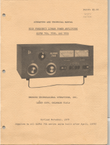
ALPHA 89
HF LINEAR POWER AMPLIFIER
ALPHA/POWER, INC. RF Power for Communications and Industry
14440 Mead Court – Unit B, Longmont, Colorado 80504
(970) 535-4173
*
FAX (970) 535-0281

TABL
E OF CON
TENTS
INSTALLING YOUR ALPHA 89 .................................................1
OPERATING YOUR ALPHA 89 ..................................................2
1.0 - INTRODUCTION ...................................................................................................................3
2.0 - OVERVIEW OF AMPLIFIER CAPABILITIES ......................................................................3
3.0 -ALPHA 89 SPECIFICATIONS ................................................................................................4
4.0 - UNPACKING AND PREPARATION .....................................................................................5
Figures 1-3 Transformer installation ................................................................................................6
Figure 4 Inside top view ..................................................................................................................7
Figure 5 View with front panel lowered ...........................................................................................8
5.0 CONTROL & INDICATOR FUNCTIONS ................................................................................9
Figure 6 Front Panel .......................................................................................................................10
6.0 - INSTALLATION ...................................................................................................................11
Figure 7 Rear panel connections .....................................................................................................11
7.0 - OPERATION .........................................................................................................................12
Table Tuneup Settings ....................................................................................................................14
8.0 - FAULTS AND PROTECTIVE FUNCTIONS ........................................................................15
9.0 - TROUBLESHOOTING SUGGESTIONS ..............................................................................16
10.0 -ALPHA 89 FUNCTIONAL CONFIGURATION .................................................................17
ILLUSTRATIONS
Figs. 1-3, Transformer installation ...................................................................................................6
Fig. 4, Inside top view .....................................................................................................................7
Fig. 5, View with front panel lowered ..............................................................................................8
Fig. 6, Front panel view .................................................................................................................10
Fig. 7 Rear panel connections ........................................................................................................11
Fig. 8, ALPHA 89 Simplified schematic ................................................. .......................................18

CA
UTION! !
READ BEFORE PROCEEDING!
TO AVOID SERIOUS DAMAGE NOT COVERED UNDER
WARRANTY READ THIS MANUAL CAREFULLY BEFORE
INSTALLING YOUR ALPHA 89
The ALPHA 89 is easy to install, but failure to carry out each procedure exactly as described in this manual is likely to
lead to amplifier damage which is not covered under warranty. Damage to other station equipment also may result.
Important precautions are given on this and the next page.
INSTALLING YOUR ALPHA 89
1. Be careful not to twist or warp the chassis when handling the amplifier with its cover removed. Never lift the chassis
by one comer when the transformer is in place.
2. When installing or removing the transformer, move carefully and follow the instructions in this manual exactly. When
installing, insure that all connectors are properly mated and fully seated. Don't force them! Tuck the transformer handle out
of the way so it doesn't interfere with the cover. It is necessary to install at least one of the transformer bolts to eliminate
potentially hazardous voltage buildup between the transformer and chassis.
When removing the transformer, carefully unlock the mated connectors and gently pull them apart.
3. Insure that both tubes are solidly seated in their sockets with the red silicone rubber chimneys firmly seated against
the chassis.
4. Connect the green conductor in the ALPHA 89 power cord only to the power source neutral or ground. Connecting
the green wire to a "hot" line is almost certain to cause immediate damage. Triple check your wiring before plugging
in!
5. Make sure the primary power tap is connected to the tap closest to your actual AC line voltage. See manual section 4.3.
6. Never install cover screws longer than 1/4". Longer screws may penetrate internal boards or wiring and cause severe
damage. Make sure each screw hole in the cover is aligned with its corresponding captive nut in the chassis before inserting
screws.
7. Remove blower motor shipping hardware from rear chassis wall. Save the two 10-32 bolts, fiber washers, and rubber
shim; reinstall this hardware whenever the chassis is transported.
8. Solidly bond all station equipment together. Heavy braid, such as the outer conductor of RG-8/U coaxial cable, is
recommended for the purpose. This is important for personal and equipment safety as well as to avoid RF feedback.
9. DON'T apply AC power with the cover off without contacting ETO customer service first. You may damage both
you and your amplifier!
1
101193

C
A
U
T
I
O
N
! !
READ BEFORE PROCEEDING!
TO AVOID SERIOUS DAMAGE NOT COVERED UNDER
WARRANTY READ THIS MANUAL CAREFULLY
BEFORE OPERATING YOUR ALPHA 89
The ALPHA 89 is easy to operate, but failure to carry out each procedure exactly as described in this manual is likely to
lead to amplifier damage which is not covered under warranty. Damage to other station equipment also may result.
Important precautions are given on pages 1 and 2 of this manual.
OPERATING YOUR ALPHA 89
1. You must set transceiver power output properly! The ALPHA
89 requires only 50 watts drive for full rated output. Virtually all
damage results directly from severe overdrive. Damage caused by applying far more than rated drive power to the
ALPHA
89 will not be covered under warranty. Fortunatel
y, most modem transceivers maintain quite consistent output from band
to band and mode to mode if set up properly.
Setting the transceiver POWER or RF PWR control IS NOT SUFFICIENT
Several popular transceivers can generate RF spikes of 200-300W or more unless the transceiver internal drive level
also is
adjusted carefully according to its manufacturer's instructions. Typically this is done with a knob labeled DRIVE (IC-
781,
FT 1000), PROCESSOR OUT (TS-940, TS-950) or, on SSB when speech processing is not in use, MIC or MIKE.
2. The ALPHA 89 "faults" into STBY or OFF when unsafe operating conditions occur. If this happens the fault can be
cleared by removing excitation, switching from operate to standby and back to operate, and then re-applying excitation.
3. To operate the ALPHA 89 efficiently, cleanly, and safely at any desired peak power output, it must be properly loaded
and driven for that power level. If peak power output (and hence drive) is to be changed significantly, the amplifier must
be reloaded and tuned. See section 7.
4. Induced energy from nearby electrical storms or other power transients may damage components.
Such damage is not covered under warranty. It is important to use a good lightning arrestor, and it's
good practice also to disco
nnect and ground antenna feedlines, and to disconnect AC power, when the equipment is not in
use.
HAPPY OPERATING!
2

1.0
-
INTRODUCTION
This Manual provides all the information necessary to install and operate your ALPHA 89. Sche-
matic diagrams are available on request, at no charge to owners. For your own protection please
return the Owner Registration Card immediately and advise ETO of any future address change
promptly.
1.1 - OWNER ASSISTANCE
Assistance is available from ETO Customer Service (Communications Products) at (719) 599-3861,
260-1191, by FAX at (719) 260-0395, or by mail. ALPHA technical specialists also may be contact
through the same office.
101193
3
2.0
-
OVERVIEW OF AMPLIFIER CAPABILITIES
It is extremely important to thoroughly review Installation and Operation sections of this manual
before attempting to use the ALPHA 89. Failure to do so could result in serious damage not covered
under warranty.
The ALPHA 89 is capable of 1.5 kW continuous RF output on all commonly-used modes and on any
authorized amateur frequency from 1.8 to 29.7 MHz.
The ALPHA 89 is compatible with all popular amateur BF transceivers and exciters. It requires
approximately 50 watts peak RF drive for 1.5 kW output.
The ALPHA 89 is capable of full break-in CW (QSK) and all digital modes when used with any
appropriate transceiver. The ALPHA 89 control system incorporates protective functions that mini-
mize the probability of accidental damage to the amplifier or its power tubes. In most cases, when
one of the protective functions is "tripped," a front panel LED indicator will display the fault (e.g.,
excessive grid or plate current, load reflected power/ VSWR, etc.)
For extended RATT or other very high duty cycle service, use of the ALPHA 89 optional auxiliary
cooling fan, available from ETO, is strongly recommended. With reasonable care, your ALPHA 89
should provide exceptional performance and satisfaction for many years.

3.0
-
ALPHA 89
SPECIFICATIONS
Frequency Coverage: All amateur bands 1.8-29.7 MHz* plus most non-amateur frequencies 6.0-19.0
MHz and 20-30 MHz.
* NOTE: FCC rules do not permit new amateur amplifiers to be operable on 24-30 MHz as delivered within the U.S.
& possessions. Owners who send ETO Customer Service a photocopy of their authorizing amateur license will
promptly be provided information on "unlocking" 12 and 10 meter coverage.
Band Change & Tuning: Manually controlled by the operator.
Power Output: 1500 watts PEP, keyed CW or continuous carrier, no time limit. Auxiliary
cooling fan (optional) recommended for high duty cycle continuous operation.
Drive Power: Typically 50-60 watts for full rated output
Input VSWR: < 1.5:1 within amateur bands; < 2:1 elsewhere.
Tube Complement: Two Eimac 3CX800A7 triodes in grounded grid.
T/R System: Heavy duty PIN diode switch. Switching time approximately 1 mS. Enclosed
mechanical bypass relay.
ALC: Grid-current-derived, adjustable to -lOV maximum.
Harmonic Output: Better than 55 dB below rated output.
Intermodulation: Better than 36 dB below rated output.
Fault Protection: Plate overcurrent, grid overreurrent, high reflected power (load VSWR), T/R
mis-sequencing, gain (i.e., severe mistune or RF are), overdrive, other.
Displays: Dedicated LED bargraphs for peak Pout, Prefl, and lg, plus switched bargraph for average
Ip, HV, TUNE indicator, drive power, and load VSWR.
Cooling: Full cabinet ducted-air, rear intake/top exhaust Floating blower mount for quietest
operation.
Primary Power: 190-250V (200, 220, 240V nominal taps), 50-60 Hz, single phase; fused 20A.
Size & Weight: 17.3"W x 7"H x 16.5"D (439 x 178 x 419 nun) excluding controls, feet &
connectors; 75 lb. (34 kg) net.
4

4.0 - UNPACKING AND PREPARATION (Ref. figs. 1-4, pages 6-7)
4.1 Unpack amplifier and transformer. Inspect both for physical damage. Save all packing material for
future use. Warning! Do not ship amplifier in other than factory packing or equivalent.
4.2 Remove cover by removing all screws except the two located in the perforated tube exhaust areas.
Inspect carefully for shipping damage. If damage is discovered in either of these two steps notify ETO
Customer Service immediately.
4.3 Connect the proper internal line voltage tap. The ALPHA 89 may be operated from any AC power
source of 190-250V, 50-60 Hz, 20 ampere capacity. A 4-terminal barrier strip for tap selection is located
toward the back chassis wall to the left of the transformer. DO NOT MOVE the wire connected to the
terminal marked PRE If necessary, move the other wire to the tap (200, 220, or 240V) closest to your
nominal AC line voltage.
4.4 Install Transformer. Position amplifier flat on a table with the right side of the chassis facing forward
Install the transformer per Figures 1 through 3, using its sling handle. Use care not to pinch or damage
wiring or components. You may wish to have a helper steady the chassis during the following steps.
Align the threaded holes or captive nuts in the transformer base with corresponding chassis holes.
Taking care not to torque or twist the chassis, carefully extend it over the edge of the table just far
enough to loosely screw in at least one, and preferably both, of the two outside transformer mounting
bolts (1/4-20 hex head with flat washes, supplied). The following step is recommended but not
mandatory...
Do not stand the amplifier on edge or move it further over the table edge. Instead, rotate it so as to
extend the two inner transformer mounting holes, one at a time, over the table edge and loosely install the
bolts. Now center the transformer as much as possible so that both sides are well clear of metal work.
Orient the chassis as above while tightening all 4 bolts.
One of the transformer connectors plugs into the AC power wiring near the top/rear of the chassis center
partition, on the power supply side. The remaining two connectors plug into the top of the power supply
board immediately in front of the transformer. Proper mating of these connectors is obvious with
reasonable care; look first and make sure they match! (See Fig. 3 view A-A) Make certain the connectors are
properly mated and seated, but don't force them; they mate and latch easily.
4.5 Insure that both tubes are fully seated in their sockets with their red rubber chimneys firmly
contacting the chassis.
4.6 Make sure the HV crowbar works smoothly.
4.7 Replace the cover and carefully reinstall all screws. Be careful not to force or cross-thread screws.
Never use screws longer than 1/4"!
5


7


5.0 CONTROL & INDICATOR FUNCTIONS (See fig. 6, page 10)
5.1 RF OUTPUT, GRID CURRENT, and REFLECTED POWER bargraphs are peak-reading and generally
self-explanatory. Example: 1.5 kW output (forward power into a 50 ohm load) is indicated when all green
LED segments to the left of the 1.5 (kW) label are fully lighted and the first red LED segment is dark. The
primary calibration point for RF OUTPUT is at 1.5 kW on 14 MHz.
5.2 TUNF/IP/HV/DRIVF./LOAD VSWR "multimeter": The function of this indicator is selected by buttons at
its right. It is a moving-dot display. HV (plate voltage) is read on the 0-3 kV top scale. Ip (average plate
current) is displayed on the 0-1.5 A next lower scale. INPUT DRIVE is read on the same scale as Ip, with full
scale 150 watts. VSWR (3:1 maximum) is read on the bottom scale. The TUNE meter function permits fast
and safe manual tuneup at reduced power.
5.3 BAND switch: Each band switch position selects the amateur band indicated in MHz.
5.4 TUNE control: Varies plate tuning capacitor to set output circuit to resonance.
5.5 LOAD control: Varies plate loading capacitor to establish optimum amplifier power output level.
5.6 CW/SSB rocker switch: Selects optimum operating bias for emission type. CW provides highest efficiency
for non-linear modes including CW and FM, and SSB provides best linearity for SSB, AM, and SSTV (also
okay for CW and FM).
5.7 OPR/STBY rocker switch: Selects operate or standby modes.
5.8 ON and OFF rocker switches: momentary action switches turn the ALPHA 89's main AC power on or off.
5.9 Special rear-panel connections:
a) ALC & ALC Adjust - See section 8.3.
b) RELAY - Switches amplifier from receive to transmit when connector center pin is shorted to ground.
c) KEY OUT - Provides a contact closure which follows the keying line connected to the RELAY jack
whether the amplifier is in ON, STANDBY, or OPERATE condition. Useful for special T/R hook-ups when
amplifier is used with exciters having poor T/R sequencing. Contact ETO customer service for specific
advice.
9


6.0 INSTALLATION (Refer to fig. 7, page 11)
6.1 Connect a 50 ohm coax cable 60-72" long (supplied) from the transceiver RF output to
the ALPHA 89's RF INPUT jack.
6.2 Connect a transceiver T/R control line which is shorted on transmit and open on receive to
the 89's RELAY jack, using a standard "RCA" ("phono") plug. Cable should be shielded type.
6.3 Connect a nominally 50 ohm antenna for the frequency to be used to the 89's RF OUTPUT jack.
6.4 If desired, connect a cable from the the ALC jack to the transceiver ALC input, using an RCA
plug. See sect. 8.3.
6.5 Connect a heavy copper strap or braid from the ground stud & wing nut on the rear panel of the
ALPHA 89 to the chassis of the transceiver and other station equipment, and to the main station RF
ground.
6.6 Connect to AC power consistent with tap selected. CAUTION! Be sure the 89 green wire con-
nects to AC ground or neutral!
11
REAR PANEL CONNECTIONS
FIGURE 7

7.0 OPERATION
If the ALPHA 89 already is tuned and loaded for the operating frequency, it is necessary only to turn
on the amplifier, wait 3 minutes for tube warm-up time delay to complete, then switch to OPERATE
and apply drive. Before operating on a frequency or band different from that previously used, the 89
must be re-tuned by the operator. Re-tuning is a simple process that takes only a few seconds.
7.1 Preparation forALPHA 89 Tuneup
a) Press POWER ON button. Select preliminary BAND, TUNE, and LOAD control settings from the
"tuneup settings" chart, page 14.
b) When the three minute tube warm-up cycle ends, the red WAIT LED will extinguish. Depending
upon the setting of the OPR-ST13Y (operate-standby) switch, the appropriate status LED above it will
then light. Set the switch to STBY (standby); the STBY LED should then be illuminated. -) Set
transceiver to provide a steady unmodulated RF carrier (e.g., CW, AM, or RTTY/FSK).
d) Determine proper control settings for transceiver peak output of 50 watts. The ALPHA 89's builtin
drive power wattmeter may be used to measure and set transceiver power. To do this, first put the
amplifier in ST13Y so transceiver power is bypassed to the antenna. Then press the multimeter IP and
RV buttons simultaneously; the green LEDs in both buttons will illuminate. Driving power is indi-
cated on the 0-1.5 scale with full scale = 150 watts.
e) Adjust transceiver output to approximately 50 watts, note its power output control setting, then
reduce output to ZERO. NOTE: Most transceivers have an internal drive (or "processor out") control
which determines the internal ALC voltage. This must be adjusted according to the manufacturer's
instructions to avoid overdrive and distortion. f) Set the amplifier multimeter to Ip. The bargraph will
read at or near zero until drive is applied. g) Switch the amplifier from STBY to OPR (operate).
h) Set the SSB-CW switch to SSB. (Tuning should be done with the amplifier in the SSB (linear) mode
regardless of intended emission type. i) Set transceiver to transmit (manual lock-key, MOX, or PTT).
7.2 Normal tuneup using the TUNE meter
To tune up for nominal peak RF output of 1500 watts the goal is to adjust LOAD and TUNE controls
alternately until the lighted TUNE LED is positioned at the mid-scale "V" mark. Proceed as follows:
a) Preset the ALPHA 89's BAND, TUNE, and LOAD controls to the positions given in the "tuneup
settings" chart on page 14.
b) Select the multimeter TUNE function and apply approximately ten watts drive. (The TUNE LED
12

will not deflect from its resting position with less than 5-8 watts; until the amplifier is properly tuned, applying
more than 15 watts may cause a protective TUNE fault.)
b) Adjust TUNE control to move or "dip" the TUNE bargraph LED as far to the left as possible.
c) After step (b)...
1) If the TUNE indicator is to the left of the desired (mid-scale "V") position, adjust LOAD clockwise
until the indicator moves to the desired position, OR...
2) If the indicator is to the right of the desired position, adjust LOAD counter-clockwise instead.
d) Repeat steps (b) and (c) until the TUNE indicator is positioned as desired. See para. 7.5 for final tuning
check.
7.3 Tuneup for peak RF output greater than 1,500 watts a) Follow steps 7.2
a) through 7.2 d) above except make final adjustments so that the second or third LED to the right of
the mid-scale "V" mark is lighted.
b) See para. 7.5 for final tuning check.
7.4 Tuneup for RF output of 1000 to 1400 watts a) As above except make final adjustments so the first or
second LED to the left of the "V" is lighted. b) See para. 7.5 for final tuning check.
7.5 Final double-check of tuneup adjustment (perform after completing 7.2, 7.3, or 7.4 above)
a) Briefly increase drive power until amplifier grid current just reaches its normal peak value of 35-50 mA; note
RF output.
b) If output is close to desired value, tuneup is complete.
c) If output is greater than desired, reduce LOAD control setting very slightly and repeat steps (a), (b), and (c).
d) If output is less than desired, increase LOAD setting slightly and repeat this section.
7.6 Alternate tuneup procedure not using TUNE indicator
a) Preset ALPHA 89 controls per "tuneup settings", page 14.
b) Slowly increase transceiver output to 25-30 watts. Adjust amplifier LOAD control to maximize RF output.
Then adjust TUNE and LOAD alternately until no further increase in output can be obtained.
c) Carefully adjust transceiver output until amplifier grid current just reaches but does not exceed 3550 mA and
note amplifier RF output. Then proceed to c) or d) below, as appropriate.
d) If RF OUTPUT after step c) above is less than desired...
1) Increase LOAD setting until grid current drops below 35 mA.
2) Adjust TUNE control to maximize Ig.
3) Repeat these sections c) and d) as necessary, until desired RF output is achieved with 35-60
mA Ig,
1
3

OR
e) If RF OUTPUT after step c) is greater than desired...
1) Reduce transceiver drive until Ig drops below 35 mA.
2) Reduce LOAD setting until Ig rises to about 45 mA.
3) Adjust TUNE for maximum Ig.
4) Repeat sections c) and e) as necessary, until desired RF output is achieved with 35-50 mA 1g.
CAUTI0N! If, during operation at or below desired power on any band, the grid current exceeds 70 mA, turn
LOAD to a higher setting (to increase loading) and then adjust TUNE for maximum RF OUTPUT Repeat if
necessary until peak grid current at desired output does not exceed 50-60 mA.
IMPORTANT: As the final tuneup step, always adjust TUNE for maximum RF output.
7.7 - TUNING NOTES
a) At resonance, plate current is minimum (dipped) while grid current and RF output are at or very near maximum
(peaked).
b) Increasing the TUNE control dial reading increases tuning capacitance.
c) Increasing the LOAD control dial reading decreases loading capacitance; this is because decreasing capacitance
increases actual loading.
d) Excessive grid current can be corrected by reducing transceiver output or increasing amplifier loading.
e) FCC rules do not permit new amateur amplifiers to be operable on 24-30 MHz as delivered within the U.S. &
possessions. U.S. owners who send a photocopy of their authorizing amateur license to ETD customer service will
be provided information on "unlocking" 12 and 10 meter coverage. (ETO is not permitted to perform this very
simple operation for you.)
TUNEUP SETTINGS
MHz TUNE LOAD
1.9 50 30
3.7 77 57
7.2 45 40
10.1 22 65
14.2 22 65
18.1 47 82
21.2 32 86
24.9 44 84
29.0 12 90
14

8.0 - FAULTS AND
PROTECTIVE
FUNCTIONS
8.1 Soft Faults: Two conditions may cause soft faults...
a) Improper operating conditions, usually overdrive (and possibly excessive plate or grid current), high load
VSWR, or improper T/R control cable connections or timing.
b) Abnormal amplifier conditions (e.g., low bias) which may result in damage only in the transmit mode.
When such a condition occurs, the control system automatically switches the amplifier to STBY and the
appropriate FAULT LED illuminates to indicate the nature of the fault (see front panel pictorial).
To reset a soft fault...
a) Return the transceiver to receive
b) Switch the ALPHA 89 to STBY (standby)
c) Correct the condition that caused the fault
d) Return the ALPHA 89 to OPR (operate), and...
e) Resume transmission
8.2 Hard Faults: Failures such as HV shorts (extremely high plate current) or bias or control system failure result
in immediate shutdown of amplifier AC power to avoid damage.
To reset a hard fault...
After the cause of the hard (power-off) fault is found and corrected, simply press the ON button and wait for
warnrup time-delay to complete. Resume operation when desired.
8.3 ALC: No ALC connection normally is needed when using modern transceivers having smooth RF output
control. In the rare case where faults or distortion occur because transceiver output canno be well controlled it will
be necessary to contact the transceiver manufacturer for assistance to determine the correct technique to reduce
transceiver output. This may require adjustment of internal transceiver controls. See section 9, "overdrive-related
faults", for further information.
15
10119

9.0 - TROUBLESHOOTING SUGGESTIONS
Most apparent problems with the ALPHA 89, especially when first putting one into operation, result
directly from failure to observe carefully the procedures given in this manual, especially those given as
cautions on pages 1 and 2. A few other points learned from experience are given here.
Footswitch use: Users have found that some footswitches exhibit severe contact bounce which can
intermittently cause improper T/R sequencing. Usually this shows up as amplifier dropout (transceiver
bypass to the antenna) on occasional CW characters or SSB transmit periods. A capacitor of about
.001-.05 mfd placed directly across the switch contacts normally cures the problem.
Overdrive-related faults: These nearly always result from failure to set up the transceiver power controls
(there may be two controls which interact) according to manufacturer's instructions. In the rare situation
when transceiver output cannot be controlled adequately, with reference to page 2, item 1, ALC control
feedback to the transceiver might help solve the problem if the transceiver has an external ALC input and
a conventional negative-going-firom-zero ALC system (Refer to fig. 7, page 7a for what follows.)
Connect the transceiver ALC input line to the ALPHA 89 ALC jack using an "RCA" type plug and
shielded cable. Turn the ALC control pot adjustment fully counterclockwise. Then, while driving the
amplifier with about 50W peak drive, turn the ALC control pot clockwise just far enough to eliminate
overdrive faults and/or distortion - with some transceivers this may be only a fraction of a turn.
Ideally, the ALC is checked with an oscilloscope connected between the amplifier's RF output and the
load. With the amplifier initially in standby the transceiver is driven with a two-tone audio signal and the
RF waveform observed. No waveform distortion or peak clipping should be evident. With the amplifier
switched on-line the waveform on the `scope should be of greater amplitude but "clean" as before.
If you do not have a `scope, the following procedure will probably prove satisfactory:
Check under CW carrier and SS13 voice conditions for any indication of distortion or "motorboating"
(signal instability or oscillation). If any is detected, reduce the ALC control setting (CCW) until the
distortion disappears. Alternate between drive and ALC control adjustments if necessary to obtain
smooth operation.
Do not expect ALC to be an overdrive "cure-all". ALC should be used only to provide fine adjustment of
transceiver output (say, reducing it from 55 or 60 to 50 watts) rather than gross limiting (150 watts down
to 50). Expecting transceiver ALC range to handle gross overdrive is unrealistic; the transceiver may not
be able to accept such excessive control voltage input and will probably have a severely distorted signal.
This signal will then be "linearly" amplified by the ALPHA 89 so that it is not only loud but obnoxious as
well, earning the unlucky operator the distinction of being a one-man pileup on the frequency!
16

10.0
-
ALPHA
89 FUNCTIONAL CONFIGURATION
Figure 8 on the following page is a simplified block diagram of the ALPHA 89.
1) Principal functional components are emphasized as follows:
a) Heavy rectangular boxes represent individual modules of the amplifier, in most (but not
all) cases circuit boards (PCBs).
b) Signal paths used in both transmit and receive are shown by heavy solid lines.
c) Signal paths used only in transmit, by heavy dashed lines.
d) Signal paths used only in receive, by heavy dotted lines.
e) Internal wiring harnesses are shown as light solid lines. Each is labeled with the
designations of the control, monitoring and power distribution lines which comprise it.
f) Principal interfaces to the outside (connectors & controls) are located around the
perimeter of the block diagram.
2) Transmit signal path: Drive from the transceiver, applied at the TX RF INPUT connector, passes
sequentially through the input wattmeter, tube deck T/R section, input t/r pcb, input matching net-
work, (pair of) 3CX800A7 triode tubes, plate tuning network, dual pin diode pcb, output t/r pcb,
and output wattmeter pcb to the tx rf out/rx rf in jack.
3) Receive signal path: Tx rf out/rx rf in jack, output wattmeter, output t/r pcb, input t/r pcb, tube
deck t/r section, and input wattmeter to the tx rf input jack which is of course also the rx signal output
to the transceiver.
While the complexity of the ALPHA 89 is such that describing its circuitry in detail here is
impractical, one set of schematics will be provided at no charge to any owner on request, and
assistance with specific questions or problems is always available from ETO Customer Service.
1
7
10119

/