Page is loading ...

- ~~
f"-~
,j;
"'"
~~ -
~
I ,
-
- .
-"
?-
OPERATING AND TECHNICAL MANUAL
,.
HIGH FREQUENCY LINEAR POWER AMPLIFIERS
ALPHA 76A, 76PA, and 76CA
.....
",.
~
~ .
=
EHRHORN TECHN8LOGICAL OPERATIONS, INC.
'"0
...
CANON CITY, COEOEADO 81212
~
=Revised November, 1978
(Applies to all ALPHA 76A series units built after April, 1978#-
~ ~
.,.
]!
-
.-.
-
--
"=
"
I
1
.I
""
:;;
~
1
=
-"
,.
...
~
~
.
;;:;
~ ~
.
"
-~
. ~
~
~
."
~.
~
~
~
I
I
. J
~
~
"
'.
~
I
~
"]
I
I
..;
.i.--
PRICE: $5.00
=
\-N1..fJV
MA>-rcR

"0
TABLE OF CONTENTS
">
SECTION 1 - General Description and Specifications. . .
SECTION 2 - INSTALLATION. . . . . . . . . . . . . . . .
Interconnections with other equipment. . .
Preparing blower fo."" operation. . . . . . .
SECTION 3 - OPERATION
. . . . . . . . . . . . . .
Initial tune-up. . . . . . . . . . . . . .
Operation at 1 KW and 2 KW input. . . . . .
Operating notes. . . . . . . . . . . . . .
Troubleshooting hints. . . . . . . . . . .
SECTION 4 - THEORY OF OPERATION
. . . . . . . . . . . .
'0
SECTION 5 - ILLUSTRATIONS. . . . . . . . . . . . . . . 11
Transformer access & location. . . . . . .11
Rear panel view of amplifier. . . . . . . .11
Top view showing major component locations. 12
Schematic diagram. . . . . . . . . . . . . 13
Front panel view. . . . . . . . . Front cover
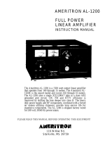
SECTION 6 - STANDARD ELECTRICAL PARTS
ETO/"ALPHA" PRODUCTS WARRANTY
. . . . . . . . . 14
. . . . . Inside back cover
/ - 7/ r -2(;0 - //11 {?f/O/I/E"
J - ;1/7-26'0 -631S- ?~,X
A~ o~
tole;~
EHRHORN TECHNOLOGICAL OPERATIONS, INC.
CANON CITY, COLORADO
81212
11/78
U.S.A.
to
1
2
3
3
4
5
6
7,
8
9
I
I
I
l

~
~
~
I
I
t]
-1-
SECTION 1
1
I
-I
GENERAL DESCRIPTION
The ALPHA 76A is a self-contained high frequency linear power ampli-
fier capable of continuous operation at d-c plate input powers in
excess of two kilowatts PEP for SSB voice and one kilowatt average
or continuouscarrier,with no time limit (NTL). The ALPHA 76A is
tunable over the range 1.8 - 2.0 plus 3 - 24 MHz, optimized fpr
convenience in the five amateur bands 15 through 160 meters.
(Export-only models with "E" suffix have six bands extending to
30 MHz, including the amateur 10 meter band.)
SPECIFICATIONS:
Model PA-76AF (U.S.) & PA-76AE (Export only)
~
I
.
Frequency Coverage: 1.8-2.0 and 3-24 MHz (including 15-160 meters).
Model PA-76AE: 1.8-2.0 and 3-30 MHz.
Plate Power Input: To 2.5 KW PEP/SSB, 1 KW average or carrier, CCS.
Typical Efficiency: 60% (RF output/d-c input).
Drive Power: Nominal 100-120 watts PEP, 60-80 watts carrier.
Input & Output Impedances: Nominal 50 ohms resistive, unbalanced;
load VSWR 2:1 or less.
Distortion: Third order 1M more than 30 dB below 1 KW PEP output.
Harmonics: 50 dB or more below mean fundamental frequency output.
Tube Complement: Two Eimac 8874 ceramic triodes in grounded-grid.
Cooling: Full-cabinet, ducted forced air; centrifugal blower.
ALC: Negative-going, adjustable threshold. (Amplifier ALC not
normally used with broadband, solid state transceivers.)
HV/LV Tap Change: Internal relay standard.
Protection: Primary fuses, plate overcurrent relay, AC and HV
interlocks.
Primary Power: 220-250V/IOA or 110-130V/20A, 50-60 Hz, 1 phase.
Size: 7.5" h x 17" w x 14.75" d (19 x 43 x 38 cm).
Weight: 65 Ib (30 kg) net; 75 Ib (34 kg) shipping, two cartons.
Options and Model Variations Available:
Option "L" -- Lightweight Hipersii!Dpower transformer reduces
weight by approximately 20 Ib; ratings unchanged.
ALPHA 76PA -- Model PA-76PA is identical with PA-76A above except
tube complement is three 8874's. Increased (con-
tinuous) tube cathode current rating provides very
long tube life; especially attractive for extended
RATT, SSTV, or A~ operation at 1 KW input on low
voltage, instant switchover to 2+ KW PEP without
retuning.
ALPHA 76CA -- Model PA-76PA with a~ernate extra-duty, epoxy-
encapsulated Hipersi~ power transformer. Reduces
weight by 10 Ib while providing extra margin for
extended duty and/or unfavorable environments.
I~
I
I
~

'"
I
I.
I
I.
,
I
I
,
I
I
f
,
I
"""
~-
- ---
-2-
SECTION 2
INSTALLATION
1. Unpacking: Carefully remove amplifierand transformerfrom car-
tons; SAVE PACKING MATERIAL
FOR RE-USE -- SHIPMENT OF YOUR
ALPHA IN OTHER THAN FACTORY PACKING MAY RESULT IN DAMAGE NOT
COVERED UNDER WARRANTY.
Inspect closely for evidence of shipping damage; if found,
notify delivering carrier and seller at once. Complete war-
ranty registration form and mail to ETO at once.
2. Transformer Installation: The cover of the amplifier is easily
removed. Remove the three flat head Phillips screws'from the
front edge on top, two pan head screws from the rear flange of
the top cover, and five pan head screws from each end of the
cover -- then lift it carefully off. (If your amplifier has a
flat head screw in the center of the top surface of the cover,
REMOVE IT ONLY IF THE SLOTS ARE CLEAR AND THE SCREW UNPAINTED.)
Orient the transformer so that both multi-pin, molded plugs on
the transformer harness point toward the front of the amplifier;
move the corresponding mating connectors in the amplifier itself
temporarily out of the way. Carefully lower the transformer in-
to position so that the i-20 tapped mounting holes in its base
line up with corresponding holes in the amplifier base plate.
Install the i-20 bolts and washers provided, and tighten.
Check both pairs of connectors visually for proper mating orienta-
tion (avoid excessive harness bending or twisting, as it may cause
damage to wires or connector pins) and mate them firmly, pushing
until the integral latches engage.
). Electrical Installation: The amplifier is normally shipped from
the factory wired for 220-250V operation. If it is to be operated
instead on 11O-1)OV lines, change over the connections as described
below before replacing the cabinet cover.
Changeover to 11O-125V Operation - Locate the six-terminal barrier
strip on the right side of the center chassis partition, above
and to the left of the transformer. With short jumper wires only
between lugs #2 and #~ the amplifier is connected for 24ov power
supply. Substituting instead a jumper between terminal #1 and
#2, another between #3 and #4, and a third between #5 and #6, re-
connects for 120V power source. (See sketches below.)
l@ Q)--fi @ (5)@ ~
CONNECTIONSFOR 24ov
r@) ft-fi-fi ~
CONNECTIONS FOR 120V
Power Cable Connection- The green wire of the amplifier power
cable is a chassis safety ground, and must always (and only) be
connectedto the safety ground of the a-c mains -- NEVER to one
of the "hot" power wires. The black and white wires are inter-
changeable and connect to the two "hot" service conductors.
~
l
I
,
,
I
I
I
,
~
j
~J
01

fb
't)
'0
-3-
4. Physical Location: Your ALPHA must be located so that intake of
cool air through the rear panel, and exhaust of warm air through
the top cover perforations, is not impeded in any way. A minimum
of 4 to 6 inches of clearance should be allowed behind and above
the amplifier for air circulation. Be careful not to block the
top-cover exhaust openings with log books or equipment.
5. RF And Control Connections: Interconnection of the ALPHA for
operation with any popular transceiver or exciter is extremely
simple. . Connect the rear panel jacks as follows:
RF INPUT - Use an appropriate plug and RG-58C/U or similar
small 50 ohm coaxial cable to connect to transceiver or exciter
"rf output" or "antenna" connector. KEEP CABLE AS SHORT AS POS-
SIBLE -- PREFERABLY NOT LONGER THAN 2i TO
3 FEET.
RF OUTPUT - Use a standard PL-259 ("UHF" type) plug and RG-8A/U
or similar coaxial cable (50 ohm) to connect to antenna system.
RELAY - Use a standard "phono-type" patch cable to connect this
jack to transceiver or exciter contacts which are "open" on re-
ceive and "shorted"on transmit ("N.O."= "normally open").
Nearly all transceivers provide such contacts via either phono-
type jacks or other accessory connector on the rear panel.
NOTE: When the amplifier is OFF, or in the RECEIVE condition
with no short across its RELAY line, the RF OUTPUT connector is
internally connected directly to the RF INPUT, providing normal
"transceive-type" antenna input to the receiver.
ALC - For use with tube-typetransceivershaving negative-going
ALC systems with external input jacks, simply patch this jack to
the mating one on the transceiver or exciter with a standard
"phono"-type cable. Nearly all modern solid state (broadband)
transceivers utilize positive-going internal ALC, with a detector
at the rf output point. This internal system normally functions
adequately to control SSB drive power to the amplifier; in fact,
most such exciter/transceivers provide no external ALC input jack
and it is entirely unnecessary to make any ALC connection.
6. Blower: The cooling blower is mounted on a new "absorbent foam"
cushion pad which dramatically reduces transmission of mechanical
noise and vibration. Two 10-32 Phillips head screws secure the
blower motor to the amplifier rear panel for safety during shipment,
and must be removed for quietest operation. These two screws are
identified with arrows in FIGURE 2 on page 11 of this manual. Re-
move both screws, and the rubber strips wedged between the rear
panel and the blower motor bearing housing (between and slightly
above the screws); save for future shipping. SERIOUS PHYSICAL
DAMAGE TO AMPLIFIER AND BLOWER MAY RESULT IF SCREWS AND SHIM
STRIPS ARE NOT PROPERLY RE-INSTALLED BEFORE SHIPPING AMPLIFIER!
J
\
I
';;;;3

-4-
SECTION}
OPERATION
1. Control Functions:
BAND - Selects tuning range of amplifier,indicatingthe nominal
center of the band in MHz.
TUNE - Controls operating frequency. In general, higher frequency
bands (14 & 21 MHz, etc.) tune toward the "0" end of the
vernier dial scale, lower frequencies tune toward 50-100.
LOAD - Controls amplifier loading ... the power input level at
which best efficiency and linearity is achieved. Higher
bands load normally toward the 70-100 end of the vernier
scale, lower bands typically vary across most of the dial
depending on frequency and load impedance or VSWR. In
general, higher dial numbers result in heavier loading.
PUSH BUTTONS -
ON: Depressing momentarily applies a-c power to amplifier.
Also press to restore power after overcurrent relay
has tripped, interrupting main a-c power.
OFF: Depress momentarily to remove a-c power from amplifier.
~
HV: Multimeter monitors high voltage - JOOOV full scale.
~I Multimeter monitors grid current - 150 mA full scale. ~J
FWD: Multimeter monitors forward RF power - 2000W full scale.
~I Multimetermonitors reflectedRF power - 200W full scale. I
CW: Selects lower plate voltage for CW/FSK/SSTV and other
types of emission, including SSE, up to 1 KW d-c input.
SSE: Selects high plate voltage for 2+ KW PEP SSE input.
OUT = STBY: When both the CW and SSE buttons are out (as
evidenced by black color windows), the amplifier is
placed in the STANDBY condition. Antenna changeover
relay is disabled, 'permitting "straight-through" op-
eration of exciter/transceiver while amplifier remains
ready for immediate use if desired.
Rear panel screwdriver adjustment sets the drive power level
at which ALC voltage begins to rise from zero. Use a small
insulated screwdriver to avoid accidentally sporting circuit.
ALC -
2. Tune-Up Procedure:
(a) GENERAL - The objective of tune-up is to adjust the amplifier
to deliver maximum power output at the desired level of plate
d-c power input, or at the available level of rf drive power,
whichever is lower.
When the amplifier is adjusted for maximum attainable rf power
output with a specific, fixed level of rf carrier drive power,
it is automatically set up properly for the best combination
of efficiency and linearity possible at that drive level.
~
~
1

-5-
~
~
If the drive power is increased beyond the tune-up level
after the final TUNE/LOAD adjustments, flattopping and un-
desirable distortion (on SSB) will result, along with grid
current greatl~ in excess of normal.
If drive power is reduced below the tune-up level without fur-
ther adjustment of TUNE and LOAD controls, amplifier efficiency
will be reduced. Both of these statements are applicable to
any linear amplifier of the types used for high power amateur
and similar service.
It is therefore essential that the amplifier be adjusted for
maximum rf output at the drive and d-c input powers which are
to be employed in normal operation, WITH ONE IMPORTANT EXCEPTION:
if the plate voltage is changed without changing also the TUNE
and LOAD adjustments, the resulting power level which will yield
optimum performance at the new plate voltage will vary in pro-
portion to the square of the plate voltage change. For example,
if the ALPHA 76Ais tuned up for maximum output with 1400 VDC
plate voltage and with the drive level set so that the result-
ant maximum output is about 700 watts (equivalent to a d-c
input of roughly 1000 watts), THEN if the plate voltage is
increased to 2000 VDC the amplifier will automatically perform
optimally at about 700 X (2000/1400)2 = 1400 watts rf output,
corresponding to approximately 2000 watts d-c input.
In general, the final operating adjustment after basic tune-
up should be to adjust excitation (drive) from the exciter or
transceiver so that the G~ID current meter indication just
reaches about 50 made (1/3 scale) key-down or on voice peaks.
(b) INITIAL TUNE-UP - Place amplifier in STANDBY (both CW and SSB
buttons out: if one is already depressed, partially depress
the other one and release, so that both pop out and show black).
(1) Press HV button and watch MULTIMETER HV scale (0-3 KV).
(2) Press ON button and release. Panel meters should immedi-
ately illuminate red or amber and the MULTlMETER should
swing promptly to indicate 1.5 KV t 100V (mid-scale).
(If this does not occur, press OFF immediately and locate
problem.) The blower should also start immediately and
exhaust air should be detectable flowing from cover vents.
(3) When tube warm-up delay is completedin 45-90 seconds,
th€ meters will change to pale blue or green, indicating
"ready" to transmit. Set controls to the preliminary
points indicated in Table I below, depending on the
desired operating frequency.
TABLE I -- PRELIMINARY SETTINGS FOR INITIAL TUNE-UP
FREQ. MHZ BAND TUNE LOAD FREQ. BAND TUNE
1.8 1.8 84 30 7.1 7 50
2.0 1.8 75 25 14.15 14. 20
3.6 3.5 53 38 21.20 21 10
3.9 3.5 42 48 28.70* 28* 08*
(*"E" suffix models
~
LOAD
45
70
82
90*
only.)
, J
]
I
1
1
1
.
".
il
(I
fJ
!
.1
1
I
I
~
!j
]
.~
~
m
L.
~
~
!~
~,
.
~
~
~
'I
/11
.~~

-6-
(4) Press CW button and switch exciter to CW or TUNE; the
ALPHA panel meters should turn amber, indicating 'trans-
mit.'
(5) Very slowly increase exciter carrier output until the
amplifier PLATE CURRENT meter indicates half-scale --
about 0.5 ampere. Press FWD and carefully adjust
LOAD for maximum RF WATTS meter reading. Then adjust
TUNE for maximum indication on the meter (FWD RF WATTS).
Repeat the process of alternately peaking first LOAD,
then TUNE, until no further increase in FWD RF WATTS
can be achieved.
(6) Note PLATE CURRENT meter indication; the desired
reading for one kilowatt d-c input is approximately
0.7 amp (since 0.7 amp X 1400 volts = 980 watts input).
(7) If the plate current in step (6) was less than 0.7 amp,
increase exciter carrier output slightly and repeat
the LOAD-TUNEadjustmentprocess of steps (5) and (6)
again. If the plate current in step (6) was greater
than 0.7 amp, decrease exciter output slightly and
repeat the process.
(8) Continue the process outlined in step (7) until, after
the final LOAD-TUNE adjustments, the PLATE CURRENT
meter indication is as desired.
The ALPHA is now correctly adjusted for operation at one
kilowatt DC input using the "CW" (low) plate voltage tap..
(c) OPERATION AT 1 KW INPUT (KEY-DOWN OR PEP/SSE) - Tune up as
in (b) above. Leave amplifier in CW mode. No further ad-
justment is required for CW-FSK-~STV operation except to
check exciter rf output under operating conditio.s to insure
that plate current is as desired. Also press GRID and check
that grid current does not exceed about 50-75 ma-(1/3 to 1/2
scale) .
For SSE to approximately 1 KW PEP input, set mike gain or
equivalent exciter rf output control so that amplifier GRID
current meter does not swing above about 30-50 ma on speech
peaks (less than 1/3 scale).
(d) OPERATION ON SSE AT 2+ KW PEP INPUT (1 KW AVERAGE) -Tune up
exactly as in (b) above. Remove excitation and press SSE
button.
Switch exciter to normal SSE and, while speaking normally
into the mike, adjust mike gain until EITHER (1) amplifier
PLATE CURRENT meter swings just reach approximately 0.45 amp
(just under half-scale) on highest speech peaks, OR (2)
amplifier GRID current meter swings just reach 50 ma (one-
-third scale), whichever occurs first.
Maximum legal (U.S.) amateur power input of one kilowatt
average corresponds to the condition described, assuming
that plate voltage (HV) is approximately 2.2 KV on speech
peaks (i.e., 0.45 amp X 2200 volts = 990 watts average).
A slight increase in loading will reduce grid current peaks,
if necessary to achieve desired plate current swings.
~.
01
"I
r
,
~
~\¥I

~
~
"
-7-
3. Operating Notes:
(a) TUBES - The 8874 ceramic triodes are extremely rugged and
normally operate with a large margin of safety. They will
deliver outstanding service life IF not damaged by grossly
excessive grid dissipation or airflow blockage (keep the
intake and exhaust vent areas clear!) Do not allow average
late current per tube to exceed 0.35 amp for more than 15-
seconds nor ever to exceed O. am. Do not allow griq
current to ever exceed full scale 150 mal; normal operation
requires only 50-60 ma.
(b) INTERLOCKS - The ALPHA 76A(all versions) is equipped with
switches which shut off a-c power and short out the high
voltage power supply when the cover is not securely fastened
in place. THESE PROTECTIVE INTERLOCKS ARE PROVIDED TO PRO-
TECT YOU AGAINST POTENTIALLY FATAL ELECTRIC SHOCK RESULTING
FROM CONTACT WITH OPERATING VOLTAGES INSIDE THE AMPLIFIER.
THE AMPLIFIER SHOULD NEVER BE ENERGIZED WITH THE COVER REMOVED
AND INTERLOCKS DEFEATED EXCEPT BY THOROUGHLY TRAINED AND
KNOWLEDGABLE SERVICE PERSONNEL!
(c) FUSES - Except in rare instances of component failure, the
blQwing of one or both primary line fuses indicates that the
maximum safe average power input capability of the amplifier
has heen substantially exceeded. USE ONLY lOA CERAMIC FUSES,
EXCEPT 15A for 76CA option, up to 20A for 120V operation.
The slo-blo fuse F3 located just behind the front panel pre-
vents burn-out of the step-start resistors and HV rectifiers
in the event of abnormal turn-on .conditions or HV faults.
DO NOT SUBSTITUTE a fuse of differenttype or rating.
(d) PLATE OVERCURRENTRELAY - Thisrelayfunctionsprimarilyto
de-energize the primary power quickly in the event of a fault
in the HV circuitry or grossly excessive drive conditions.
The relay should not be relied on to prevent either short-
or long-term overdrive; that is the operator's responsibility.
Should the overcurrent relay trip, removing all a-c power from
the amplifier, it is essential to determine and correct the
cause before re-applying power by actuating the ON button.
(e) MAINTENANCEANDTROUBLESHOOTING- Most apparentfailuresand
problems with the A~PHA 76Aseries result from operators' fail-
ure to read and thoroughly understand the contents of this
manual, as well as basic linear amplifier principles --
rather than from actual equipment defects.
Amplifier interiors, particularly the high voltage d-c areas
of the power supply and rf compartment, should be cleaned
.frequently enough (with a soft brush and a vacuum cleaner) to
prevent visible accumulation of dust. If extremely dusty
conditions prevail, it may be advisable to secure a thin
plastic air filter, of the type used in window air conditioners,
across the air intake area.
J
'I
I
1
I
II
I
,1;
t
I
I
Ii
~
I
.
?
1
'I
~
1
L
~
1!1
fl
!
r'
,J

a) Excessive drive power and/or
inadequately-heavy loading.
b) Flashover of variable capaci-
tor on voice peaks.
c) Antenna or feedline arcing
on peaks. .
d) RF feedback from antenna into
exciter or microphone line.
NOTE: If exciter manufacturer does not provide instructions for.
adjustment of ALC, set pot R40 for desired amplifier plate current
swings on peaks and adjust mike gain for'degree of ALC action
desired for normal exciter operation.
TABLE II -- TROUBLESHOOTING HINTS
SYMPTOMS
1. Won't turn on; nothing hap-
pens when ON button pushed.
2. Relay closes (and blower may
start) but no HV or meter
illumination at turn-on.
3. Blower starts, HV normal,
but meters'do not switch to
green and amplifier will not
switch to transmit.
4. Grid meter "pins" at low
drive levels.
5. Low grid current, excessive
input VSWR (abnormal exciter
loading), low rf output.
6. Plate current flows in re-
ceive or STBY conditions.
See also no. 9 below.
7. Low drive and output power;
cannot drive exciter to nor-
mal input or output levels.
8. Flashover in RF compartment,
usually between load capaci-
tor :plates.
9. Plate current flows in re-
ceive or STBY and cannot
drive amplifier; abnormal
exciter loading.
10. Distorted SSB output sig-
nal; possibly severe TVI.
r
- 8-
POSSIBLE CAUSELcURE
~.
a) External a-c wire, fuse, or
breaker open or missing.
b) Cover a-c interlock open.
c) Fuse Fl or F2 blown or missing.
a) Step-start relay K2 not clos-
ing; possible blown fuse F3,
defective +28V supply (D13-
D-14 or C7?), or HV fault.
a) Defective reed relay K6.
b) Defective Q1, C8, or R29.
a) R28 open or damaged.
a) Bias zener D8 damaged or open.
b) R28 damaged or open (but grid
current will read very high).
a) 8874 tube leak or short, cath-
ode to grid or heater.
b) D7 defective or damaged.
a) ALC sensitivity control R40
set improperly; unplug ALC to
check. See note bottom of pg.
a) Excessive load VSWR; mismatch
or wrong antenna; defective
rf cables or connectors.
b) Insufficiently heavy loading
and/or excessive drive power.
c) Dirt or other contaminant in
capacitor plates.
d) If chronic, capacitor plates
damaged by previous arcing.
a) 8874 tube short, cathode-to-
grid or cathode-to-heater.
~.
L-
~I
I

-9-
~
SECTION 4
tP(e
THEORYOF OPERATION
1. RF Amplifier Section: Tubes VI and V2 (and V] in models 76PA and
76CA) are parallel-connected in a grounded grid configuration.
+28 volts of cathode bias is applied via R7 and L7 to cut off
plate current during non-transmit periods; bias is reduced to an
operating level of 5.1 volts when the antenna relay is actuated.
RF excitation is applied to the cathodes via an input network,
including a broadband, toroidal ferrite input matching transfor-
mer, which is carefully designed to present to the exciter a
nominal 50 ohm load with linear characteristics. Changing this
input network may result in excessive input VSWR.
The plate output circuit is a full pi-L network consisting of
C16, L1-L2-L], C17, and L4. The pi-L provid.e.s harmonic suppression
substantially better than a simple pi network, as well as somewhat
better efficiency in this application.
An rf directional wattmeter, consisting of L9 and associated
ponents, senses forward and reflected power in the rf output
for display on the panel meter when selected by push-buttons
and REFL, respectively.
Excitation voltage.is detected and filtered by ALC rectifier C2]-
C24, D15, and associated components. The drive level at which
negative-going ALC is generated (i.e., the threshold level) is
set by rear-panelpotentiometerR40 which back-biases D15.
Relay K4 switches the antenna straight through to the exciter
when the amplifier is OFF or in STBY or receive conditions, per-
mitting normal transceive operation. K4 switches the ALPHA 76A
into the transmit configuration when an external short is placed
across RELAY control jack, J].
com-
line
FWD
~
2. Power Supply:Tr~former Tl is a 1.5KVA continuous-serviceunit
(2.4 KVA Hipersi~core for 76CA only) which supplies all re-
quired a-c operating voltages for the amplifier.
High voltage d-c for the tube anodes is rectified by a full-wave
bridge, DI-D4, and filtered by a ]0 mfd., 2.7 KV capacitor con-
sisting of CI-C6 in series. These computer-grade electrolytic
capacitors are factory capacitance-matched to insure uniform a-c
ripple voltage distribution and long service life.
High voltage tap-change relay K] selects high or low transformer
voltage taps, as controlled by the front panel CW/SSB push but-
ton switches.
Cover interlockswitch s4 prevents actuation of the main power
relay KI unless the cover is secured in place. Safety "crowbar"
S5 places a low-resistance short across the HV supply (and dis-
charges the filter capacitor bank) whenever the cover is opened.
J
I
J
'I'
I
.~
I
1
.
"
.~
1
I
~
4
1
L
1
I
~~

FWCT rectifier Dl)-D14, and filter capacitor C7, provide +28 V
for.bias and control circuitry. A 25 VAG transformer winding is
"bucking" connected to provide approximately 95 VAG for the
blower, resulting in a reduced noise level but virtually the
same air delivery as at full voltage.
Dual primary windings on Tl permit connection for either 110-
125 V or 220-250 V operation, as described in the Installation
section of this manual. No wiring change is necessary for opera-
tion from either U.S. standard 120-N-120 or from typical overseas
220-250 V without "central"neutral -- two-wire systems. The
third power cable (green) wire is simply a chassis safety ground.
). Control And Meterin~ Circuits: ON/OFF push buttons S2 control
self-latching main power relay Kl. Resistors Rl and R2 limit
the initial current inrush to 12 amperes maximum.,and are shorted
by relay K2 when the HV filter capacitor approaches full charge
(the delay is only a few tens of milliseconds). Fuse F) protect~
against burn-out of Rl and/or R2 in the event of mistakes or faults
which prevent K2 from closing properly.
During the required heater warm-up period, the 8874 tubes are
protected against plate current flow by a 60-second (nominal)
time delay circuit consisting of MOSFET Ql and associated compon-
ents. Until C8 reaches sufficient voltage to close K6 via Ql,
T/R relay K4 is prevented from closing regardless of external
RELAY line conditions. Hence, standby (cut-off) tube bias is
maintained and rf drive cannot be applied to the tubes.
After time delay K6 closes, an external shor~ placed across 3)
(the RELAY jack) closes T/R relay K4, provided that either the
CW or the SSE switch is depressed (if both are "out," the T/R
relay is locked out, leaving the amplifier in standby-condition).
Actuating K4 reduces the cathode bias applied via R7 to the +5.1
volts determined by zener D8. This operating bias level permits
slight plate current flow under idling.conditions in the SSE
(high voltage) mode; with lower voltage applied for CW, tdling
plate current is c10se to cut off.
Plate current is metered directly by M2. Grid current is measured
across R28 in the grid return circuit and high voltage is metered
directly via precision multiplier resistors Rl)-R15.
Excessive plate current (as evidenced by abnormal voltage drop
across R6) actuates overcurrent relay K7, which trips out Kl.
Status-indicating meter lamps 11 through 14, which are controlled
by Q2 and Q), illuminate the meters amber when K6 is open (dur-
ing the time-delay interval) and when the external RELAY line is
shorted so that the T/R relay is in the transmit condition.
When the time delay relay is closed but the T/R relay is not
actuated (amplifier in STANDBY and/or external RELAY line open),
the green lamps illuminate the meters, signifying "ready."
~
-10-
~
1
~
~

SECTION 5 -- ILLUSTRATIONS
~
FIGURE 1 - Transformer Access & Location
FJ
C1,C2
~
FIGURE 2 - Rear View
-11-
AC POWERSTRIP
FOR 120/24ov
SELECTION
P2 (UNMATED)
J2 (UNMATED)
T1 POWER
TRANSFORlVIER
J1/P1 (MATED)
.~
ALC
THRESHOLDADJUST
J
I
:J
I
I
I
..
"'I
I
.
I
11
'1
I
1
~
I
L
""
,
~

FIGURE J - Top View Showing Major Component Locations
AC JUMPER STRIP
Jl PI Tl
Bl
(VJ)
VI
V2
L5
Ll
LJ
Lll
C16
L2
.......--
-12-
.~
'\
P2
J2
R6
01t
RIJ-RI5
D2,D4
Dl,DJ
CBl
cI-C6
R7-R12
11-14
(?

~
-14-
~
SECTION 6 -- STANDARD ELECTRICAL PARTS
SYMBOL DESCRIPTION
Bl Howard'#3-90-8507
Cl-c6 120-180uf/450V
compo grade elec.
C7 500uf/50Velect.
C8 15uf/20V tantalum
C9,C19,C26 .002uf!lKVdisc
CIO-C13,C36,C37.002uf/3KVdisc
C14 2 x .002uf/6KV
C15,C20-22,C25,
C27, C33, C34,C41.01uf/50V disc
C18,C28-C30 .02/500V disc
C23 27pfdipped mica
c24 100pf dipped mica
C32 2-8pf air trimmer
C38 300pf dipped S.M.
C39 10uf/5PVelect.
C40 18 pill KV disc
..
DI-D4
~
D5
D6,D15,D18,D19
D7
D8
D9
DIO-D14,D17
D20
Fl, F2
F3
11-14
Kl
K2
K3
K4
K6
K7
~
i.
3KV PIV/.5A CCS,
RCC 1733
IN4746 (18V/IW)
IN4148 or IN914B
IN4722 or IN5404
IN4733 (5.1V!lW)
IN4757 (51V/IW)
IN4004 (400V/IA)
10A/250V, type
3AB or ABC (76CA
only, 15A)
l!A slo-blo, type
MDL or equiv.
#387, 28V lamp
DPST/120VAC,Guard-.
ian 1390-2C-120A
DPST/24VDC, Guard-
ian 1395-2C-24D
HV relay, 24vDC,
PB #PRDIIDYO-24
DPDT/IOA, Phillips
39CIID24
5 VDC coil, SPST N.O.
5"'09 A 1>C.
24 VDC coil, SPST N.O.
\%00 .Q t>c
SYMBOL DESCRIPTION
L5,L6,L7 15uhy/IA RFC
L8,Lll 1 to 2.5 mhy RFC
LIO 1 mhy miniature
Ql
Q2,Q3
MPF121 or similar
dual-gate MOSFET
2N5826 or equivalent
RESISTORS: All are i watt, 5%
carbon compo or film unless
otherwise specified below.
Rl,R2 10 ohm/12W wirewound
R3 750 ohm/2W 10% compo
R4 10K/12W wirewound
R5 150 ohm/lW 10% compo
R6 25 ohm/25W wirewound
R7-R12 2 x 120K!2W 5% compo
R13-R15 IM/l%J/4W precision
R16 180K/iw
R18 10-15K
R31 470 ohm/2W compo
R32,R34 4.7K
R36 3.3K/2W 10% compo
R38,R40 5K trim2ot, linear
R41,R42 22 ohm/!W 5% carbon
R43
R44
R28
1
I
I
.1
I
1
~
1.8K
10 ohm/! watt/5%
ALL COMPONENTS SUBJECT TO CHANGE
WITHOUT NOTICE. COMPONENTS NOT
LISTED ARE SPECIALS AVAILABLE
FROM ETO. SPECIFY MODEL AND
SERIAL NUMBER OF AMPLIFIER PLUS
CIRCUIT SYMBOL OR DESCRIPTION
WHEN ORDERING REPLACEMENTS.
'1
I
I
.,
"I
1
1
1
I
.,
1
1
I
.,
.""
I
Sl
Centralab JV9034
'"
-,
S2,S3,S6
8 station special push
I
button assembly
J
S4
Microswitch V3L-4-D8
I
Vl,V2,V3
Eimac type 8874
.,

~
8Lr\CL__~
L6 15M hy
CII
I
C3°-L
,02T
I
-_J
~
I
I
I
I
~ _L_u~:;r::l~::K- -- - - - -- - - - - - --
J;
,- --
I -, RF
- I ~39 r-l I ..2.EC nON I
I - ---J 50v ~ rt-,!
I .018 T+ L
- - ~ IN4148 -
--,~..o
1&,.'" IC32
IRF INPUT!
J4
IALe. ouT1
J6
I-
I C2-:
I ~ J; R3470
L, ,
11 *C26
.002
I --
- L
I'
I
ICB3
1
1__-
-----.-
DI5
IN4148
RL8
IO-12K
rR""FOim
J5
C27
+2tJVVEL
I' - - --
"
GI9
:002
ITSI-2~!. WHVGRN
I
I
VEL.
POWER t -.
I
CONTROL
8 SEC TION
n 'I
7- K2 I
GRAY IPCB
fiY~
K3 R28
I
1'0..n..
ORG
VIO
VR RTN
8ROWN
1<4
~
NOTiS:
& 28 MHZ "E" SUFfIX ONLY
& PA-76PA (&"C100LY
& ALL D'i IN4004 UNLESSNOTED
&
IK V UNLESS NOTED
.&
& XFMR LEAD COLORS APPLY TO.STD
PA-76 XFMR OfIILY;HIPERSIL,XFMR
WIRE
COLORS VARY
7. ALL CAPACITORS
8. ALL RESISTORS 5
orlO% y'4W UNLESS.HOTED
FRON.
~
~
~l
06
IN4148
tw C8lt"j
~ NlPFI21
l
f
cf
Rl
-- -
52
~
~
[Qffi
......-

-13--
~2n. 240V ~2.9'!.,
t20V
r-"
(FRONT WHI YEt!
!2.@
~
102
e
02
IHVGRN
L-------
15
6-1
01
0"
-t-
02 04
CI
R7
06
't6 X 60tyi4W/'
R6
'"2¥25W
IN4148
R31
IN
4746
r IPCB
1~
I12u
R28
1
I 'O.!l.
R33
-»r-
41.
>l
..
D9
IN4757
R36
IN4J22
~
r =f~i80K
RI3
1rvy'1%
Co",
w-
RI4
IM/'~
vie
52
(jJ
~o
[Qfffi>
f6!QP>
IftITLP' B
~
-.J
~ .
EHRIjORN . TECHNOLOGICAl:. OPERATIONS, INC.
CANON CITY, CO. 81212
'1/,/7(.
MODELS PA-76A AN 76Ri\ & "Cn OPTION
PINb8
DWG NO: SCHEMATIC
fI/l.
/