Page is loading ...

Us e r ’s M a n u a l
HF LINEAR POWER AMPLIFIER
Qi bun ALFHA/powER>IN C RF Power for Communications and Industry
IlLinB 14440 Mead Court, Unit B, Longmont, Colorado 80504
p p | 4 ** (970) 535-4173 * FAX (970) 535-0281

CONTENTS
CRITICAL PRECAUTION DURING INSTALLATION 1
Section 1 INTRODUCTION 1
General Description of the ETO 91/3 Amplifier 1
Specifications, ETO 91/3 1
Figure 1 Top View 3
Section 2 PREPARING THE ETO 91fi FOR OPERATION 4
Transformer Installation 4
Inspection of Tubes & Chimneys 4
AC Primary Connections & Amplifier Grounding 4
Operation from 90-130V mains 5
Figures 2-4 Transformer Installation 6
Section 3 AMPLIFIER/STATION INTERCONNECTIONS 7
Coaxial Cable Types & Connectors 7
T/R Control Cable 7
ALC 7
Figure 5 Back Panel 8
Section 4 OPERATION 9
4.1 Control Functions 9
4.2 Tune-up 9
1. Turning On the Amplifier 10
2. Tuning Up for Operation at 1,500 Watts RF Output 11
4.3 Reflected Power Protection 12
4.4 ALC 12
Section5 OPERATING AND MAINTENANCE NOTES 13
Tubes 13
Fuses 13
Electronic Bias Control 14
Plate Overcurrent Relay 14
Preventive Maintenance 14
Section 6 TROUBLESHOOTING HINTS 15
Section 7 DESIGN AND CIRCUIT OVERVIEW 17
SCHEMATICS 19

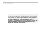
IMPORTANT
CRITICAL PRECAUTION DURING INSTALLATION OF YOUR ETO 31/?!
While the cover is removed to install the power transformer, make sure that the tubes are
properly installed as described in Section 2 below. Failure to do this may cause severe dam
age or destruction of both tubes. Such damage is not covered under warranty.
CAUTION: Only the screws securing the 91/3 top cover and front panel have ENGLISH
threads (6-32 or 8-32). ALL OTHER HARDWARE IS METRIC DO NOT REPLACE
TRANSFORMER OR OTHER SCREWS WITH ENGLISH SIZES, as doing so will damage
the captive nuts installed in the chassis.
Section 1
INTRODUCTION
General Description of the ETO 91fi Amplifier
The ETO 91/3 is a self-contained, HF linear power amplifier capable of continuous operation
at 1500 watts peak power output on SSB, keyed CW, SSTV, RTTY, digital modes or AM, with
no time limit. If periods of "con tinuous-key-dcrwn" carrier operation will exceed 5 minutes, the
optional auxiliary cooling fan available from ETO must be installed to avoid possible damage not
covered by the warranty.
As shipped, units delivered within the USA and its territories are manually tunable to cover
all HF amateur bands from 1.8 to 14.35 MHz, with extensive out-of-band capability for
operation on MARS, etc. Appropriately-licensed users may contact ETO for information
on modifying domestic amplifiers to extend coverage to 29.7 MHz.
Specifications, ETO 91fi
Frequency Coverage: U.S. units only, amateur bands 1.8-14.35 MHz as shipped (see note
above); export units, 1.8-29.7 MHz.
Power Output 1500 watts peak all modes, including SSB, CW and continuous or modulated
carrier. Carrier operation (eg., AO, RTTY or FM) for more than 5 minutes at or near maxi
mum rated power requires use of the auxiliary cooling fan accessory.
Drive Power 50 to 60 watts nominal for rated output.
Power Gain: Nominally 14 dB, a power increase of 25 times.
Input Impedance: 50 ohms nominal, unbalanced; VSWR <1.5:1.
1

C21-C24
C20
(C26 under)
Power
Supply
Board
PS/J1 J2

L4
BL1
HV Crowbar
Vacuum Relay
Power
K2 Relays
P1/XFMR
Ti
S3 Interlock
Figure 1
9ip Top View

Output Impedance: 50 ohms unbalanced.
Maximum Load VSWR: 2:1 at full rated power output.
VSWR Trip: Automatic standby when reflected power >250 watts.
Intermodulation Distortion: 36 dB below rated output.
Harmonic Output: < -55 dBc.
Tubes: Two Svetlana 4CX800A/GU74b ceramic-metal tetrodes.
Cooling: Full-cabinet, ducted forced air using cushion-mounted centrifugal blower.
Automatic Level Control (ALC): Negative from 0, adjustable.
Primary Power: 200/220/240 or 100/120 VAC nominal, 50-60 Hz, fused at 20 amperes.
Power Transformer. 3+ kVA with strip-wound Unisil-H(R) core.
Protective Functions: Primary and step-start fuses, primary AC interlock, high voltage
crowbar, peak and average plate overcurrent trip-outs, arc protection trip, reflected power
trip, grid current limiting & sustained overdrive trip.
Status Indicators: ON, WATT (initial tum-on time delay), OPERATE and FAULT LEDs.
Metering: Dedicated, full-time LED bar graphs display forward and reflected rf power; grid
current LEDs; LED bargraph selectable among plate voltage, plate current, and tune-up
functions.
Size: 7.5" H x 17' W x 15.5" D (19 x 43 x 39 cm).
Weight: 66 lb. (30 kg) net, 75 lb (34 kg) ship; two cartons.
Note: ETO reserves the right to change design and/or specifications without prior notice or
obligation.
2

Section 2
PREPARING THE ETO 91ß FOR OPERATION
Transformer Installation (See Figures 2-4)
Remove the amplifier top cover to install the transformer. Only one possible transformer
orientation allows mating all its connectors without straining leads. Lift the transformer high
enough to dear the right side chassis lip and move it sideways into the chassis. USE CAU
TION! PROCEED SLOWLY to avoid damaging wires or components. From underneath,
insert the supplied bolts with washers through the clearance holes in the chassis and into the
nuts in the transformer base. CAUTION! Mate transformer connectors carefully and gently
to insure that all connector pins engage correctly and fully.
Inspection of Tubes & Chimneys
While the top cover is removed, make sure tubes are firmly seated in their sockets, rubber
exhaust chimneys are fully and correctly installed, and anode connectors are tightly clamped
to tubes.
The silicone rubber chimneys installed on the 4CX800A/ GU74b tubes are absolutely essential
parts of the cooling system. Make sure the chimneys are straight and fully installed so that
the bottom of each chimney is firmly against the tube deck and completely covers the airflow
openings in the deck. Tube cooling air must exit only through the tube anode fins; it must not
be allowed to escape outside them. Failure to ensure proper cooling airflow may result in
tube damage or destruction which is not covered under warranty.
AC Primary Connections & Amplifier Grounding
Primary voltage taps are selected at the terminal strip numbered "1" to "7" and located on
the chassis center divider, left of and above the transformer. Connect the two wires labeled
"A" and "B" for the line voltage to be used, as shown in the following table. The two short
jumper wires supplied are not used on 200-250V, but must be connected as shown for opera
tion on 100-120V mains.
PRIMARY "A" to terminal
4 (factory setting)
"B " to terminal Tumpers
Not used for
190 to 250V
230-250V
210-230V
190-210V
110-130V
90-110V
4
5
4
5
2
3
3
6
6
operation
1 -> 2,6 -> 7
1 -> 3,6 -> 7
Power Cord Connections — WARNING!
To avoid hazard of potentially fatal electric shock and/or severe damage to the ETO 91fi
and other equipment, always use an AC plug which is appropriate for the primary mains
voltage, current rating and configuration. NEVER use 120V-type plugs and power recep-

tacles for 200-240V circuits. ALWAYS use grounding type AC connectors which conform to
local codes and ensure that the green/yellow wire in the 91 fi power cable is wired only to
the AC mains safety ground (or to neutral, as may be necessary with a 240V circuit config
ured 120V-N-120V without a separate ground, commonly found in the US).
The green/yellow conductor in the power cord is wired to the ETO 91/3 chassis. It MUST be
connected only to the power source safety ground or neutral. The blue and brown power
cord wires connect to the two "hot" wires of the AC source; either wire may be connected to
either side of the line. For best results use a dedicated 200-240V branch circuit of #10 AWG
copper wire or equivalent, rated at 20A, to feed the amplifier.
Important information concerning operation from 90-130V mains
Electrical power equipment will draw twice as much primary current from 120V mains as
from 240V mains. Therefore, operating the ETO 91/3 on a typical 120V¡20A household circuit
without exceeding the 20A circuit rating will limit maximum peak power output to about 600-1000
watts. Maximum possible RF output power for any particular primary AC voltage and cur
rent capacity may be estimated as
Po max = (Vline x Dine) / 2.3.
For example, if the 91(3 operates from a circuit which is capable of delivering 115VAC at a
maximum current of 20A, with no other loads connected to the circuit maximum peak RF
output possible without tripping the 20A breaker (or fuse) is approximately
Po max = (115V x 20A) / 2.3 = 2300/2.3 = 1000 watts.
If the same circuit also supplies a transceiver drawing peak line current of 5A and a lamp
drawing 1 A, only 20-5-1 = 14A is available for the amplifier and maximum possible output is
about
Po max = (115V x 14A) / 2.3 = 1610/2.3 = 700W.
RF Grounding
A ground stud with wing nut is provided on the rear of the chassis. Connection should be
made from this stud to a good RF earth ground, such as a copper water pipe or driven rod,
via heavy copper braid or strap. CAUTION: When using any high power amplifier, failure to
connect ALL station equipment to a good common ground may allow RF feedback to leak into the
transceiver and cause severe signal distortion.
Replacing the Amplifier Cover
Use only the 6-32 screws supplied with the amplifier and do not tighten any of the screws
until all are started.
5

3A
AC CONNECTION
VIEW A-A
HIGH AND LOW VOLTAGE BOARD CONNECTIONS
HV CONNECTION
VIEW A-A
LV CONNECTIONS
VIEW A-A
FIGURES 2-4
91 ß TRANSFORMER
INSTALLATION

FIGURE 5
91B REAR PANEL

Section 3
AMPLIFIER/STATION INTERCONNECTIONS
(See Fig. 5)
Coaxial Cable Types & Connectors
Connect the transceiver RF output to the ETO 91(3 RF INPUT with 50 ohm coaxial cable -
RG-58C/U or equivalent Use "UHF" type plugs, such as Amphenol 83-1SP, with reducing
adapter to fit RG-58.
Coaxial cable from the 91(3 RF OUTPUT to antenna should be RG-8A/U, RG-213/U, or
equivalent high quality type with a PL-259 UHF-type plug on the amplifier end. RG8X cable
is not recommended.
T/R Control Cable
The 91(3 has a full break-in vacuum relay QSK system requiring only the normal interconnec
tion when used with a modem QSK transceiver. The 91(3 requires a contact closure (short
circuit) on transmit from its RELAY jack center pin to chassis. This function is supplied by the
transceiver, usually from a dedicated relay that is normally open in receive and closed in
transmit. Shielded wire should be used for the T/R control cable. The 91(3 end must be fitted
with a common phono (RCA-type) plug and the other end with a plug suitable for the trans
ceiver (usually supplied with the transceiver).
The T/R relay contact must close before application of RF drive. 91(3 protection circuitry
prevents "hot switching" with RF drive applied. If a T/R timing problem is suspected,
contact ETO customer service for assistance.
ALC
The use of external ALC is not normally needed or recommended when the ETO 91(3 is used
with modem transceivers. However, the 91(3 does generate a negative-going ALC control
voltage that can be fed back to most transceivers if required, to minimize the possibility of
overdriving the amplifier. This external ALC voltage is available at the 91B's rear panel ALC
jack via a common phono connector. 91(3 grid current exceeding about 1mA will initiate ALC
and light the green GRID LED. About 5-10mA yields full ALC output - nominally -10 Vdc -
and the red GRID LED lights. If the exciter requires a lower ALC voltage the 91(3 ALC poten
tiometer may set accordingly. While driving the amplifier, adjust the ALC pot to limit maxi
mum transceiver output as desired. We recommend contacting ETO customer service before
attempting to use external ALC with the 91(3 .
7

Section 4
OPERATION
4.1 Control Functions (See front cover photo)
BAND - Use to select amateur band desired (in MHz).
TUNE - Selects operating frequency. Higher frequencies tend to tune toward the "0" end of
the dial scale, while lower frequencies tend to tune further toward the "100" end.
LOAD - Sets amplifier plate loading and determines the power level at which best efficiency
and linearity are achieved. In general, loading is heavier at greater scale settings. Higher
frequencies tend to load more toward the "100" end of the dial scale and lower frequencies
toward the "0" end.
POWER - Press ON to apply primary AC power to the amplifier or to reset power if the plate
overcurrent relay has tripped. Press OFF to remove primary AC power.
OPR/STBY - OPeRate places the amplifier in-line. With the 9 lß off, in STandBY, or in warm
up with the WATT LED lighted, the amplifier is bypassed and the exciter is connected di
rectly to the antenna.
Metering LEDs & Bargraphs - Separate bargraphs provide instantaneous full-time display of
peak
RF OUTPUT and REFLECTED POWER. Red and green "GRID" LEDs indicate, respectively,
that normal peak drive has been reached and the onset of overdrive and flattopping.
A switch-selected bar graph monitors three additional functions:
TUNE: Permits a simple and safe tune-up procedure to be performed at low output power.
See section 4.2 below.
IP: Plate current, 1.5 amperes full scale (approximately 75 mA per segment).
HV: Plate voltage, 3000 VDC full scale (150 V per segment).
4.2 Tune-up
Objective
The objective of tune-up is to adjust the amplifier (and the drive applied to it) to obtain
optimum efficiency and linearity at the desired output power.

Any linear amplifier must be adjusted for optimum efficiency and linearity at a specific
power level. If operation at higher power is then attempted without appropriate readjust
ment, the result will be flattopping, "splatter," and (usually) excessive amplifier grid current.
If operated at a much lower power level than it has been adjusted for, the amplifier's effi
ciency decreases considerably.
Grid Current
The ETO 91/3 operates in Class AB2 when delivering maximum output power consistent
with excellent linearity. A small amount of grid current flows and the green GRID MIN LED
lights as drive approaches the optimum level. The green GRID LED should flicker on some
SSB voice peaks, and light under CW/SSTV/RTTY carrier conditions. As overdrive ap
proaches, grid current increases rapidly and the red GRID MAX LED lights. At maximum
output and efficiency, the red LED lights dimly; full illumination of the red LED indicates
overdrive and must be avoided. If the red LED lights before the desired value of plate current
and/or power output is reached, readjust amplifier loading before continuing. On SSB,
optimum output consistait with good linearity occurs when the green GRID LED lights on
most voice peaks and the red LED flickers dimly only on the highest peaks.
Excessive grid current results from overdrive and/or inadequate loading. The solution is to
reduce drive, and/or increase amplifier loading. The 91B/s 4CX800A/GU74b tubes are well
protected and these adjustments tend to be less critical than in many other amplifiers.
ALC
The 91/3 grid current limiting circuits provide substantial tube protection against possible
damage. The ALC voltage generated by the 91/3 cannot control the amplifier itself and so is
not applied internally. If ALC control is required, a connection must be made from the 91f3 to
the transceiver ALC input. (See Sections 3 and 4.4)
Tune-up Procedure
NOTE: The forward and reflected power LED bar graphs and GRID LEDs are peak-respond
ing.
BEFORE INITIAL TUNE-UP, MAKE SURE A SUITABLE ANTENNA OR 50 OHM
DUMMY LOAD IS CONNECTED TO THE 91/3. Leave the amplifier off or in standby and
apply exciter power to make a forward vs. reflected power check. If reflected power is less
than ten percent of forward power, the VSWR is lower than 2:1 and it is safe to prooeed with
tuneup.
1. Turning On the Amplifier
* Place the OPR-STBY switch in STBY (standby).
* Rotate the multimeter selector switch to HV.
* Depress POWER/ON.

If any of the following does NOT occur, depress power OFF switch immediately and investi
gate before proceeding:
* The blower starts (note air exhausting above tubes.
* The multimeter bargraph automatically displays HV; it should indicate approximately
2.8 KV.
* The WATT LED is lighted.
IMPORTANT: EXHAUST AIR MUST BE DETECTABLE FROM THE TOP VENTS: If it is
not, TURN OFF the amplifier and verify that the exhaust chimneys are properly positioned
over the tubes. When the warm up delay is complete (about 150 seconds), the WATT LED
will extinguish. The ETO 91/3 is now "ready". ^
2. Tuning Up for Operation at 1,500 Watts RF Output
1) Preset BAND, TUNE, and LOAD controls to the nominal positions given in TABLE I,
below.
TABLE I - Preliminary Tuneup Settings
Frequency Band Tun? Lo?d
1.8 MHz 1.8 95 30
2.0 1.8 55 80
3.5 3.5 85 55
4.0 3.5 65 80
7.15 7 60 40
10.13 10 85 70
14.2 14 55 60
18.1 18-21 90 50
21.2 18-21 45 70
24.9 24-28 90 70
28.0 24-28 40 80
29.7 24-28 20 80
NOTE: Final TUNE and LOAD settings will vary with the operating frequency, antenna
characteristics, and power level.
2) Reduce transceiver carrier output control to ZERO.
3) Press OPR (operate) on OPR-STBY switch. OPR LED should light.
4) Select TUNE function of the multimeter bargraph.
IF AT ANY TIME IN THE FOLLOWING PROCEDURE THE AMPLIFIER FAILS TO RE
SPOND AS DESCRIBED, REMOVE DRIVE IMMEDIATELY!
11

5) Switch transceiver to CW and increase its carrier output to approximately 15 watts (9Iß
output approx. 300-500 watts).
NOTE! If more than about 15 W drive is applied while the 91ß is substantially mistuned, the 9lß will
switch to STBY. If the amplifier is returned to receive (key-up) it will automatically reset to
OPR in about 4 seconds.
6) Adjust TUNE control to deflect the TUNE LED maximum leftward.
7) Adjust LOAD control to place the illuminated TUNE LED below the "V" mark on the
TUNE scale.
8) Repeat steps 6 and 7 above.
9) Increase excitation until 91ß output is about 1500 watts.
10) Repeat steps 6 and 7 at least twice.
11) Touch up TUNE for maximum power output.
The ETO 91ß is now correctly tuned to deliver 1500 watts RF output on SSB, CW, FSK, SSTV
and FM. The TUNE LED normally fluctuates during modulation or keying. Illumination of
the first red LED on the RF OUTPUT bargraph indicates output has exceeded 1500 watts.
To operate at reduced power in any mode, simply decrease drive (i.e., transceiver power
output).
4.3 Reflected Power Protection
While operating, check the bargraph to ensure that reflected power remains below about 165
watts peak (2:1 VSWR when amplifier output is 1,500 watts). Fluctuating reflected power
may indicate a problem in the feedline or antenna. If reflected power exceeds 250 watts the
9Iß will automatically switch to standby. The FAULT LED will illuminate, indicating that
the 9 Iß protection system has tripped it to STBY. Such faults reset automatically if the trans
ceiver is returned to receive for a few seconds.
4.4 Automatic Level Control (ALC)
If external ALC is used, amplifier grid current peaks greater than approximately 3 mA will
initiate ALC. At grid current of 5-10 mA, ALC output is nominally -10 V. If the transceiver
requires less ALC voltage, adjust the rear panel ALC potentiometer counterclockwise until
smooth ALC action results. Increase the exciter RF output until the red GRID LED just illumi
nates on voice peaks.
A VOM can be used to measure ALC voltage while the pot is adjusted for suitable peak ALC
voltage. Many Kenwood and Yaesu transceivers work well with -8 and -10 VDC maximum,
loom transceivers generally require lower peak voltage, typically -2 to -3 VDC.
12

Section 5
OPERATING AND MAINTENANCE NOTES
TUBES - The 4CX800A / GU74b tubes used in the ETO 91/3 are very rugged and normally
operate with a large margin of safety. They should provide outstanding service for many
years if not damaged by abuse- especially overdrive or blockage of cooling airflow. Allow at
least twelve inches (31 cm) unobstructed clearance around the air intake and exhaust areas. Stacking
equipment is not recommended.
Never allow key-down plate current to exceed 1.5 amperes for more than one or two sec
onds. If you do and a plate current trip occurs, it will automatically reset in about 4 seconds if
the amplifier is returned to receive (key-up). Never allow the red GRID LED to stay brightly
illuminated for more than a second.
Frequent on-off AC power cycling may shorten tube life. It's better to leave equipment in
standby for several hours than to cycle power repeatedly on-off-on-off over the same period. *
INTERLOCKS — The ETO 91/3 is equipped with a cover interlock switch intended to remove
primary power from the amplifier, and a crowbar to short-circuit the high voltage to chassis
whenever the cover is lifted. These interlocks are designed to protect against dangerous
electric shock resulting from accidental contact with potentially lethal voltages inside the
amplifier.
WARNING! WARNING! WARNING! WARNING! WARNING! WARNING!
ALWAYS DISCONNECT THE AC LINE CORD FROM THE POWER SOURCE BEFORE
REMOVING THE TOP COVER FROM THE 91/1 FOR ANY REASON!
Cover interlocks are intended only as back-up protection against accidents. Never depend on
them! Always disconnect the power cord from the AC mains before removing the cover!
Interlock switches should never be disabled for any reason except by a skilled and experi
enced technician.
FUSES — Never replace any fuse with one of a different type or greater current rating.
Blowing of one or both primary line fuses indicates that the maximum safe average power
capability of the amplifier has been substantially exceeded or that an equipment failure has
occurred. USE ONLY 20 AMP, 250 VOLT RATED FUSES.
Slow-blow fuses F3 and F4, located above the primary line fuses, may prevent damage to the
step-start resistors and HV rectifiers in the event of abnormal tum-on conditions or HV
faults. If the AC interlock is defeated and primary power is applied while the HV crowbar is
closed, the step-start fuses normally will blow.
13

DAMAGE RESULTING FROM USE OF A FUSE OF INCORRECT SIZE OR TYPE WILL
NOT BE COVERED UNDER WARRANTY AND MAY VOID THE WARRANTY.
PLATE OVERCURRENT RELAY — This relay will quickly turn off the amplifier in the
event of grossly excessive plate current or fault in the high voltage circuitry. The relay will
not prevent tube or other damage due to either short or long term overdrive or improper
tuning. It is the operator's responsibility to ensure safe tuning, drive, and general operating
conditions. Should the overcurrent relay trip and remove AC power from the amplifier, determine and
correct the cause of the trip before turning the 91/3 on again.
IDLING PLATE CURRENT AND ELECTRONIC BIAS CONTROL (EBS)
Idling plate current of the ETO 91/3 is approximately 350 to 400 mA during transmission. A
detector senses RF drive, and reduces plate current to 30-50 mA during pauses in speech and
key-up intervals, thus substantially reducing average power supply loading, heat generation,
and wasted energy.
ARC & MISTUNING PROTECTION
FID'S exclusive circuit senses the beginning of any RF arc in, for example, a TUNE or LOAD
variable capacitor and automatically switches the 91/3 to standby within a few milliseconds.
This system has virtually eliminated RF arc damage in current ETO amplifiers. The system
similarly detects severe mis-tuning of the 91/3, and if drive exceeds about 15 watts switches
the amplifier to standby. The 15 watt threshold permits safe tuneup at low power levels
using the TUNE indicator, without aggravating and unnecessary trip-outs.
PREVENTIVE MAINTENANCE - The amplifier interior, particularly high voltage areas,
should be cleaned with a vacuum cleaner and a soft bristle brush frequently enough to
prevent visible accumulation of dust. In extremely dusty conditions it may be advisable to
secure a thin air filter of the type used for window air conditioners across the air intake on the
rear panel. The ETO accessory cooling fan also should be installed to insure adequate cooling
airflow.
There are no user-accessible lubrication points in the amplifier. Do not apply oil or grease to
any of the components. The exterior of the ETO 91/3 may be cleaned with a mild household
liquid detergent such as Formula 409 or Fantastik. Do not use chemical solvents, as these may
severely damage the front panel or cabinet finish. Never use an abrasive cleaner.
14

Section 6
TROUBLESHOOTING HINTS
A) 91/3 will not turn on; nothing happens when ON switch is pushed.
1) External AC wiring, fuse or circuit breaker may be open.
2) Amplifier cover not in place; cover safety interlock open.
3) Fuse F1-F4 open or missing; check fuses with an ohmmeter.
4) Step-start resistor R6or R7 open.
B) Amplifier turns on but no HV is indicated by the multimeter LED bargraph.
1) Multimeter selector switch in wrong position, e.g., Ip.
2) Possible HV circuit fault.
3) HV sampling resistor in power supply damaged.
4) Transformer plugged into power supply incorrectly.
C) Amplifier turns on but no multimeter indications; other LED bargraphs are operative.
1) Low voltage power supply problem.
2) Defect or damage on control board.
D) Amplifier turns on but time delay will not complete; WAIT LED does not turn off.
1) Defect or damage in timing circuitry on control board.
E) Amplifier turns on, time delay completes but amplifier will not transmit.
1) Open T/R control line from transceiver to RELAY jack.
F) Amplifier transmits but red GRID LED often lights.
1) Amplifier overdriven or underloaded; reduce transceiver output and/or increase
amplifier loading.
2) Load VSWR (reflected power) exceeds 200W.
3) Exciter output poorly controlled. External ALC may help.
G) Amplifier operates but green GRID LED will not light and plate current is low; transceiver
does not seem to be able to drive amplifier to its rated RF output power level.
1) External ALC control voltage to transceiver excessive (see section 5.6, ALC Provi
sion).
2) Input rf load resistor or bias circuitry damaged.
3) Possible damaged or defective tube(s).
H) Receive signals disappear or are severely attenuated when switching from STBY to OPR
15

1) RELAY (T/R) control cable from transceiver is shorted.
2) Transceiver locked in transmit.
I) Plate current indicated when amplifier is in STBY or receive.
1) 4CX800A/GU74b tube heater-to-cathode leakage or short.
2) Tube bias supply or T/ R bias switch faulty.
P Distorted SSB signal; possible severe television interference.
1) Excessive RF drive from transceiver and/or insufficient amplifier loading.
2) Coaxial connector, coax feedline, antenna feedpoint balun, tuner, or antenna trap
arcing on voice peaks.
3) RF feedback from antenna into transceiver via the transceiver power cord, micro
phone or key cable, or other unshielded station patch cables.
4) Poor station RF ground.
K) Low frequency audio hum on transmitted signal.
1) Defective microphone cord (especially, broken ground lead).
2) Dynamic (magnetic) microphone located within about two feet of 91/3 power
transformer. All dynamic microphones pick up some magnetically-coupled hum from
the external field of nearby power transformers. In cases where objectionable hum is
experienced while using the 91/3 and popular microphones such as the Heil series,
the problem usually can be resolved by keeping the microphone at least 18 to 24
inches from the front of the amplifier and insuring that transceiver mike gain (speech
processing) and internal drive (ALC) levels are not adjusted to exceed 10 dB. In rare
cases it may be necessary to use a ceramic or condensa- type microphone.
16

Section 7
ETO 91fi DESIGN AND CIRCUIT OVERVIEW
RF Amplifier Section (See Figure 6,11)
Two 4CX800A / GU74b tubes are employed in a grounded-cathode, grid-driven circuit.
Excellent linearity is achieved by operating the tubes as tetrodes with normal control grid
(Gl), screen grid (G2), and plate (anode) DC voltages. Drive voltage required under these
conditions is low enough to permit using an untuned input loaded by non-inductive 50 ohm
resistor Rl. A simple network (C7, C8, K2, LI, L2 in Figure 11) compensates for tube and
wiring reactances on the highest-frequency bands, yielding extremely low input VSWR
across the entire HF range.
RF negative feedback provided by un-bypassed cathode resistors R2 and R6 stabilizes ampli
fier power gain at the desired level of about 14 dB and further enhances linearity. Protection
of tubes and other components against damage due to internal tube flash-over is provided by
a gas-discharge surge suppressor, GT, connected from the screen grids to ground, as well as
DI, D2, and R8.
The ETO 91(3 RF output network is a conventional pi-L except that plate RF choke L4 is
switched by bandswitch section SIC to optimize performance across all nine 1.8-29.7 MHz
amateur bands. Two-section TUNE and LOAD capacitors C20 and C26 are switched to
provide an "electrical vernier" for smooth, easy and accurately-resettable tuneup "by the
numbers" on all bands.
Power Supplies (Figures 6,9,10)
Transformer T1 supplies all raw AC voltages required. Step-start resistors R4 and R5 in series
with the primary of T1 limit inrush current to a safe level and are shorted out by relay K2
shortly after tum-on. Cooling blower B1 operates at approximately 100VAC (provided by a
tap on Tl) to minimize noise. For heavy-duty use when operating from 50 Hz mains, the
blower motor lead shown wired to pin 5o fJl should be reconnected to pin 4 to insure optimum cooling.
Contact ETO service or (overseas) your dealer for help in making this change.
The high voltage full-wave bridge rectifier (Figure 9) consists of 600V/5A power diodes D12-
D31. Some units may employ a molded block HV rectifier assembly instead. Bridge D1-D4
provides rectified DC for the screen grids, while D5-D8 and associated components make up
the regulated bias supply.
Figure 10 shows HV filter capacitor bank C2-C10 and the monitoring points for HV and IP.
K1 is the plate overcurrent relay. MOSFET Q12 and associated components provide regu
lated screen grid voltage for the tubes and also limit maximum screen current to a safe value.
Q12 is mounted to the rear of the 91(3 subpanel for heat sinking.
17
/