Page is loading ...

HP ProLiant DL785 Server User Guide
User Guide
HP Part Number: AH233-9003B
Published: September 2009
Edition: 3

© Copyright 2008–2009 Hewlett-Packard Development Company, L.P.
The information contained herein is subject to change without notice. The only warranties for HP products and services are set forth in the express
warranty statements accompanying such products and services. Nothing herein should be construed as constituting an additional warranty. HP
shall not be liable for technical or editorial errors or omissions contained herein.
Microsoft, Windows, and Windows NT are U.S. registered trademarks of Microsoft Corporation. Windows Server 2003 is a U.S. trademark of
Microsoft Corporation. AMD is a registered trademark of Advanced Micro Devices, Inc.
Audience assumptions This guide is for an experienced service technician. HP assumes you are qualified in the servicing of computer equipment
and trained in recognizing hazards in products with hazardous energy levels and are familiar with weight and stability precautions for rack
installations.

Table of Contents
1 Component identification...............................................................................................7
Front panel components.........................................................................................................................7
Front panel LEDs and buttons................................................................................................................9
System Insight Display LEDs...............................................................................................................10
SAS and SATA hard drive LEDs...........................................................................................................12
SAS and SATA hard drive LED combinations......................................................................................12
Processor memory cell components.....................................................................................................13
Rear panel components.........................................................................................................................14
Rear panel LEDs and buttons...............................................................................................................15
Power supply LED................................................................................................................................16
Internal components.............................................................................................................................16
SPI board components..........................................................................................................................18
System maintenance switch (SW6).......................................................................................................18
System maintenance switch (SW1).......................................................................................................20
Battery pack LEDs.................................................................................................................................20
Fan locations.........................................................................................................................................21
2 Setup..............................................................................................................................23
Optional installation services................................................................................................................23
Rack planning resources.......................................................................................................................23
Optimum environment.........................................................................................................................24
Space and airflow requirements......................................................................................................24
Temperature requirements..............................................................................................................24
Power requirements.........................................................................................................................25
Rack warning and cautions...................................................................................................................26
Electrical grounding requirements.......................................................................................................27
Identifying rack server shipping carton contents.................................................................................28
Installing hardware options..................................................................................................................28
Installing the server into the rack.........................................................................................................28
Installing the cable management arm...................................................................................................28
Powering on and configuring the server..............................................................................................28
Installing the operating system.............................................................................................................29
Registering the server...........................................................................................................................29
3 Operations....................................................................................................................31
Power up the server..............................................................................................................................31
Power down the server.........................................................................................................................31
Extending the server from the rack......................................................................................................31
Removing the access panel...................................................................................................................32
Accessing the System Insight Display..................................................................................................33
Hot-plug fans........................................................................................................................................34
Replacing rear accessed hot-plug fans............................................................................................34
Replacing internally accessed hot-plug fans...................................................................................35
Removing the system battery...............................................................................................................37
4 Hardware options installations...................................................................................39
Introduction..........................................................................................................................................39
Processor options..................................................................................................................................39
Table of Contents 3

Removing the processor memory cell and airflow baffle...............................................................39
Installing a processor.......................................................................................................................41
Memory options....................................................................................................................................46
Advanced ECC memory..................................................................................................................46
Installing DIMMS............................................................................................................................46
Hard drive guidelines...........................................................................................................................47
Installing a hot-plug hard drive......................................................................................................47
Installing DVD or CD drive..................................................................................................................48
Hot-plug power supplies......................................................................................................................49
Installing a power supply................................................................................................................49
Expansion boards..................................................................................................................................51
Installing an expansion board.........................................................................................................52
Battery-backed write cache...................................................................................................................53
5 Cabling.........................................................................................................................57
Cabling overview..................................................................................................................................57
BBWC cabling.......................................................................................................................................57
SAS and SATA hard drive cabling........................................................................................................58
SAS expander cabling...........................................................................................................................58
High power graphics card cabling........................................................................................................60
6 Software and configuration utilities............................................................................61
Configuration tools...............................................................................................................................61
SmartStart software.........................................................................................................................61
SmartStart Scripting Toolkit............................................................................................................61
HP ROM-Based Setup Utility..........................................................................................................62
Using RBSU................................................................................................................................62
Auto-configuration process........................................................................................................62
Boot options................................................................................................................................63
BIOS Serial Console....................................................................................................................63
HP ProLiant Essentials Rapid Deployment Pack.................................................................................63
Option ROM Configuration for Arrays................................................................................................64
Array Configuration Utility..................................................................................................................64
Re-entering the server serial number and product ID..........................................................................64
Management tools.................................................................................................................................65
Automatic Server Recovery.............................................................................................................65
Integrated Lights-Out 2 technology................................................................................................65
StorageWorks library and tape tools...............................................................................................65
Management Agents........................................................................................................................65
HP Systems Insight Manager..........................................................................................................66
Redundant ROM support................................................................................................................66
Safety and security benefits........................................................................................................66
Access to redundant ROM settings............................................................................................66
ROMPaq utility................................................................................................................................66
System Online ROM flash component utility.................................................................................66
USB support.....................................................................................................................................67
Diagnostic tools.....................................................................................................................................67
HP Insight Diagnostics....................................................................................................................67
Integrated Management Log...........................................................................................................67
Array Diagnostic Utility..................................................................................................................68
Remote support and analysis tools.......................................................................................................68
HP Instant Support Enterprise Edition...........................................................................................68
Keeping the system current..................................................................................................................68
4 Table of Contents

Drivers.............................................................................................................................................68
ProLiant Support Packs...................................................................................................................69
Operating system version support..................................................................................................69
Change control and proactive notification......................................................................................69
Care Pack.........................................................................................................................................69
7 Troubleshooting............................................................................................................71
Troubleshooting resources....................................................................................................................71
Pre-diagnostic steps..............................................................................................................................71
Important safety information..........................................................................................................71
Symbols on equipment...............................................................................................................72
Warnings and cautions...............................................................................................................72
Symptom information.....................................................................................................................73
Prepare the server for diagnosis......................................................................................................74
Loose connections.................................................................................................................................74
Service notifications..............................................................................................................................75
Server power-on problems flowchart...................................................................................................75
Troubleshooting flowcharts..................................................................................................................76
Start diagnosis flowchart.................................................................................................................77
General diagnosis flowchart............................................................................................................77
Server power-on problems flowchart..............................................................................................79
POST problems flowchart...............................................................................................................81
OS boot problems flowchart............................................................................................................82
Server fault indications flowchart...................................................................................................84
POST error messages and beep codes..................................................................................................86
8 Regulatory compliance notices...................................................................................87
Regulatory compliance identification numbers...................................................................................87
Federal Communications Commission notice......................................................................................87
FCC rating label...............................................................................................................................87
Class A equipment...........................................................................................................................87
Class B equipment...........................................................................................................................88
Declaration of conformity for products marked with the FCC logo, United States only....................88
Modifications........................................................................................................................................88
Cables....................................................................................................................................................88
Canadian notice (Avis Canadien).........................................................................................................89
European Union regulatory notice.......................................................................................................89
Disposal of waste equipment by users in private household in the European Union.........................89
Japanese notice......................................................................................................................................90
BSMI notice...........................................................................................................................................90
Korean notice........................................................................................................................................90
Laser compliance..................................................................................................................................91
Battery replacement notice...................................................................................................................91
Taiwan battery recycling notice............................................................................................................91
Power cord statement for Japan............................................................................................................92
9 Electrostatic discharge.................................................................................................93
Preventing electrostatic discharge........................................................................................................93
Grounding methods to prevent electrostatic discharge.......................................................................93
10 Specifications..............................................................................................................95
Environmental specification.................................................................................................................95
Table of Contents 5

Server specifications..............................................................................................................................95
11 Technical support........................................................................................................97
Before you contact HP...........................................................................................................................97
HP contact information.........................................................................................................................97
Customer Self Repair............................................................................................................................97
Réparation par le client (CSR).........................................................................................................98
Riparazione da parte del cliente......................................................................................................99
Customer Self Repair.......................................................................................................................99
Reparaciones del propio cliente.....................................................................................................100
Customer Self Repair.....................................................................................................................100
Reparo feito pelo cliente................................................................................................................101
A Acronyms and abbreviations....................................................................................105
Index...............................................................................................................................107
6 Table of Contents

1 Component identification
In this section
• “Front panel components” (page 7)
• “Front panel LEDs and buttons” (page 9)
• “System Insight Display LEDs” (page 10)
• “SAS and SATA hard drive LEDs” (page 12)
• “SAS and SATA hard drive LED combinations” (page 12)
• “Processor memory cell components” (page 13)
• “Rear panel components” (page 14)
• “Rear panel LEDs and buttons” (page 15)
• “Power supply LED” (page 16)
• “Internal components” (page 16)
• “SPI board components” (page 18)
• “System maintenance switch (SW6)” (page 18)
• “System maintenance switch (SW1)” (page 20)
• “Battery pack LEDs” (page 20)
• “Fan locations” (page 21)
Front panel components
DescriptionItem
USB connector1
USB connector2
Video connector3
SID4
DVD drive5
Hard drive bay 1 right6
Hard drive bay 2 right7
Front panel components 7

DescriptionItem
Hard drive bay 3 right8
Hard drive bay 4 right9
Hard drive bay 5 right10
Hard drive bay 6 right11
Hard drive bay 7 right12
Hard drive bay 8 right13
Hard drive bay 1 left (optional)not shown
Hard drive bay 2 left (optional)not shown
Hard drive bay 3 left (optional)not shown
Hard drive bay 4 left (optional)not shown
Hard drive bay 5 left (optional)not shown
Hard drive bay 6 left (optional)not shown
Hard drive bay 7 left (optional)not shown
Hard drive bay 8 left (optional)not shown
Processor memory cell 114
Processor memory cell 215
Processor memory cell 3
1
16
Processor memory cell 4
1
17
Processor memory cell 5
1
18
Processor memory cell 6
1
19
Processor memory cell 720
Processor memory cell 821
1 Occupied by a cell filler in four-processor servers.
8 Component identification

Front panel LEDs and buttons
StatusColorDescriptionItem
UID button is not activatedOffUID button and LED1
UID button is activated for server
identification
Solid blue
Server is being remotely managedFlashing blue
Normal (system is off or in standby
mode)
OffExternal health LED2
Normal (system is powered on)Solid green
Redundant power supply failure
(system power supply is no longer
redundant)
Flashing amber
Critical power supply failureFlashing red
Normal (system is off or in standby
mode)
OffInternal health LED3
Normal (system is powered on)Solid green
System degraded (standby mode or
powered on)
Flashing amber
System critical (standby mode or
powered on)
Flashing red
NIC not used
NOTE: Rear panel NIC can show link
or activity while in standby mode.
OffNIC 1 LED4
Linked to the networkSolid green
Linked with activity on the networkFlashing green
Front panel LEDs and buttons 9

StatusColorDescriptionItem
NIC not used
NOTE: Rear panel NIC can show link
or activity while in standby mode.
OffNIC 2 LED5
Linked to the networkSolid green
Linked with activity on the networkFlashing green
No ac power to the systemOffPower button and LED6
System has ac power and is in standby
mode
Solid amber
System has ac power and is powered
on
Solid green
System Insight Display LEDs
The front panel health LEDs indicate only the current hardware status. In some situations, HP
SIM might report server status differently than the health LEDs because the software tracks more
10 Component identification
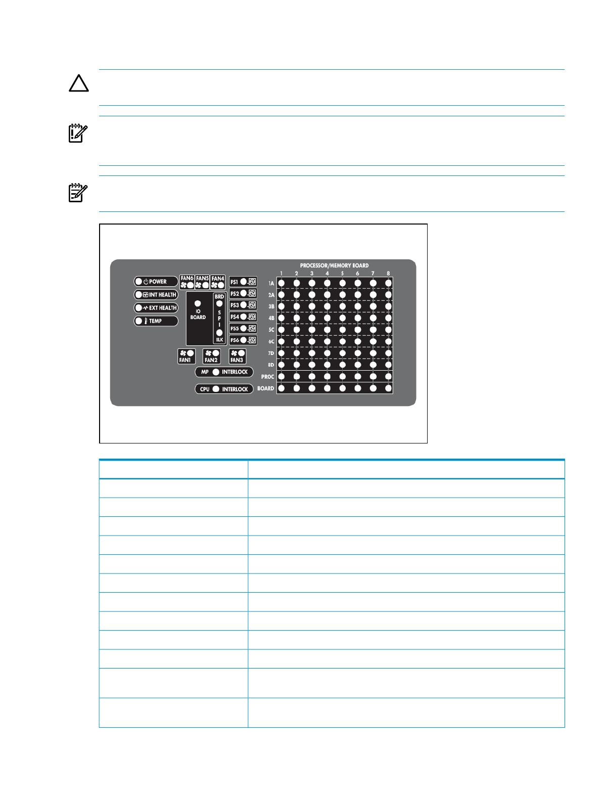
system attributes. The System Insight Display LEDs identify components experiencing an error,
event, or failure.
CAUTION: Do not block airflow by pushing the SID flush against the server while it is in the
down position.
IMPORTANT: When removing the access panel to view the Systems Insight Display LEDs, leave
the server powered on. The Systems Insight Display LEDs are cleared when the server is powered
off.
NOTE: The system management driver must be installed for the internal system health LED
to provide pre-failure and warranty conditions.
ComponentLED
System powerPOWER
Internal component healthINT HEALTH
External component healthEXT HEALTH
Over temperatureTEMP
FanFAN X
Power supplyPS X
I/O backplane powerIO BOARD
SPI board powerSPI BRD
SPI board not fully seated into the I/O backplaneSPI ILK
I/O backplane not fully seated into the midplane boardMP INTERLOCK
Processor memory board cell 8 (boot CPU) not fully seated into the midplane
board
CPU INTERLOCK
DIMM slotPROCESSOR/MEMORY BOARD X
DIMM 1A-8D
System Insight Display LEDs 11
ComponentLED
ProcessorPROCESSOR/MEMORY BOARD X
PROC X
Processor DIMM boardPROCESSOR/MEMORY BOARD X
BOARD X
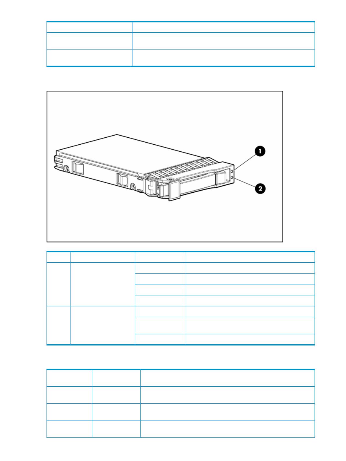
SAS and SATA hard drive LEDs
StatusColorDescriptionItem
Drive failureAmberFault/UID LED1
Fault-process activityFlashing amber
Unit identification is activeBlue
No fault-process activityOff
Drive activityGreenOnline/activity LED2
High activity on the drive or the drive is being
configured as part of an array
Flashing green
No drive activityOff
SAS and SATA hard drive LED combinations
Interpretation
Fault/UID LED
(amber/blue)
Online/activity LED
(green)
The drive has failed, or a predictive failure alert has been received for this
drive; it also has been selected by a management application.
Alternating amber
and blue
On, off, or
flashing
The drive is operating normally and has been selected by a management
application.
Solid blueOn, off, or
flashing
A predictive failure alert has been received for this drive. Replace the drive
as soon as possible.
Flashing amber
(1Hz)
On
12 Component identification
Interpretation
Fault/UID LED
(amber/blue)
Online/activity LED
(green)
The drive is online, but is not currently active.OffOn
CAUTION: Do not remove the drive. Removing a drive can terminate the
current operation and cause data loss.
The drive is part of an array that is undergoing capacity expansion or stripe
migration, but a predictive failure alert has been received for this drive. To
minimize the risk of data loss, do not replace the drive until the expansion
or migration is complete.
Flashing amber
(1Hz)
Flashing (1 Hz)
CAUTION: Do not remove the drive. Removing a drive can terminate the
current operation and cause data loss.
The drive is rebuilding, or it is part of an array that is undergoing capacity
expansion or stripe migration.
OffFlashing (1 Hz)
The drive is active, but a predictive failure alert has been received for this
drive. Replace the drive as soon as possible.
Flashing amber
(1Hz)
Flashing
irregularly
The drive is active and is operating normally.OffFlashing
irregularly
A critical fault condition has been identified for this drive and the controller
has placed it offline. Replace the drive as soon as possible.
Solid amberOff
A predictive failure alert has been received for this drive. Replace the drive
as soon as possible.
Flashing amber
(1Hz)
Off
The drive is: offline, a spare, or not configured as part of an array.OffOff
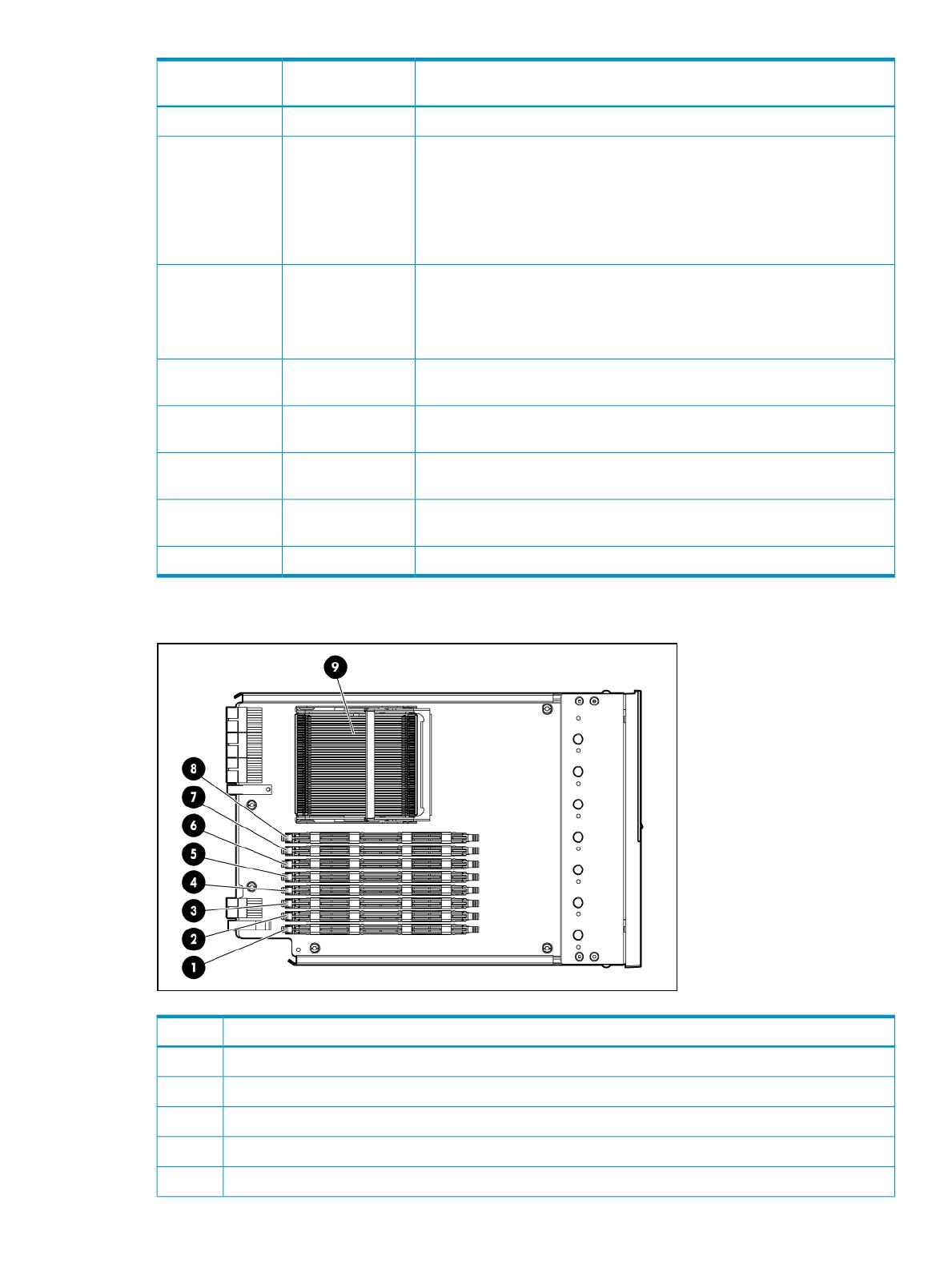
Processor memory cell components
DescriptionItem
DIMM slot 1A1
DIMM slot 2A2
DIMM slot 3B3
DIMM slot 4B4
DIMM slot 5C5
Processor memory cell components 13
DescriptionItem
DIMM slot 6C6
DIMM slot 7D7
DIMM slot 8D8
Processor socket9
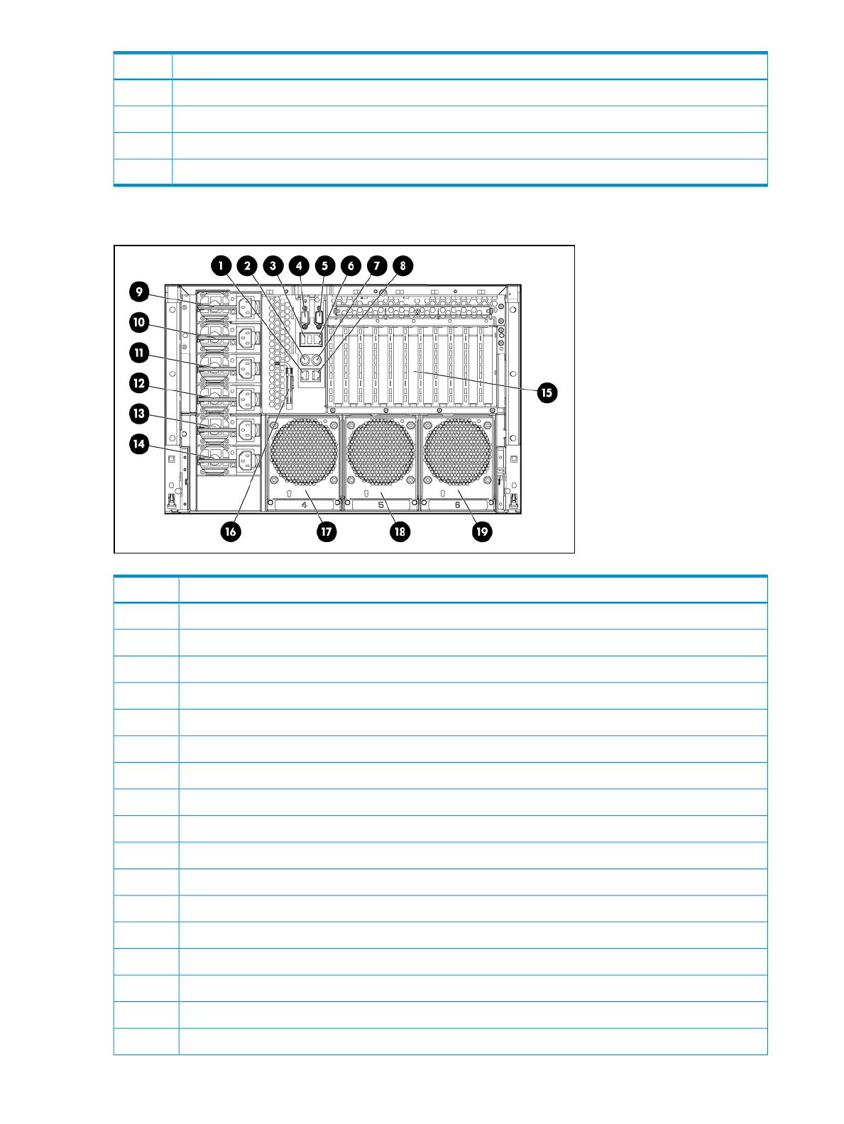
Rear panel components
DescriptionItem
NIC connector 11
Keyboard connector2
USB connector3
Video connector4
Serial connector5
iLO 2 connector6
Mouse connector7
NIC connector 28
Power supply 19
Power supply 210
Power supply 311
Redundant power supply 4 (optional)12
Redundant power supply 5 (optional)13
Redundant power supply 6 (optional)14
PCI Express or HTx expansion slots15
T-15 Torx screwdriver16
Fan 417
14 Component identification
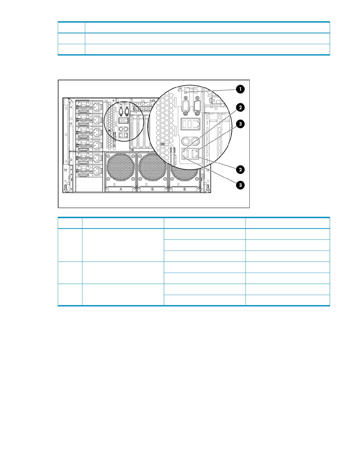
DescriptionItem
Fan 518
Fan 619
Rear panel LEDs and buttons
StatusLED ColorDescriptionItem
ActivatedSolid blueUID1
Server remotely managedFlashing blue
DeactivatedOff
Linked to networkGreenLAN Link LED2
Not linked to networkOff
Network activityGreen (solid or flashing)LAN Activity LED3
No network activityOff
Rear panel LEDs and buttons 15
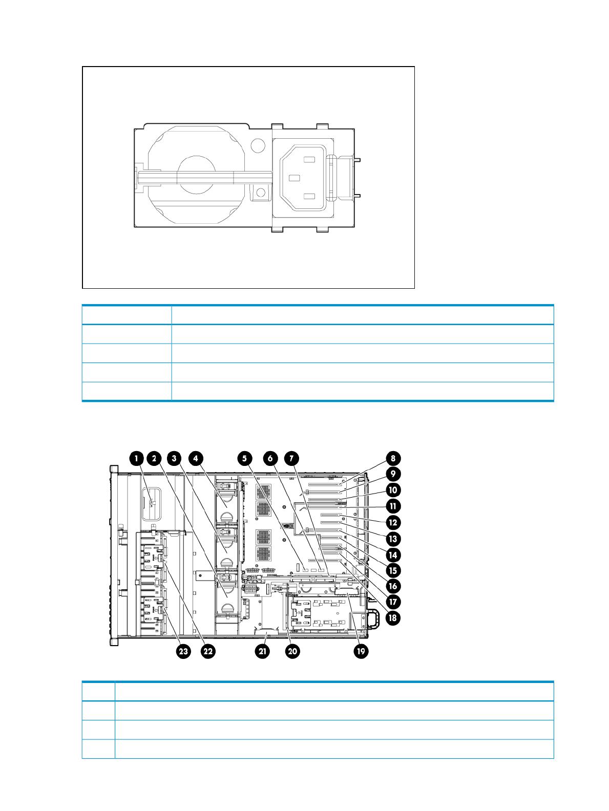
Power supply LED
StatusColor
No ac powerOff
ac power; standby power onBlinking green
Full power on; normal operationSolid green
Power supply failureBlinking amber
Internal components
DescriptionItem
Media module1
Fan 32
Fan 23
16 Component identification
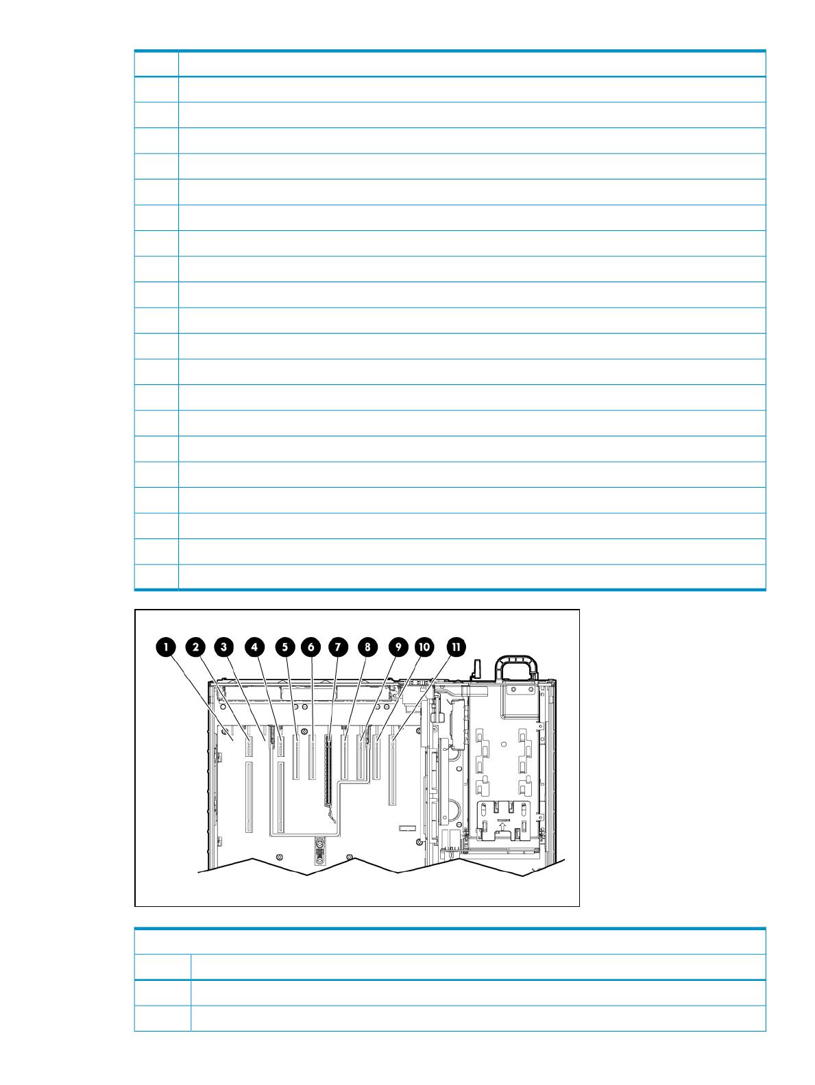
DescriptionItem
Fan 14
System maintenance switch SW65
System maintenance switch SW16
SPI Board7
PCI Express x8 non-hot-plug expansion slot 118
PCI Express x16 non-hot-plug expansion slot 109
PCI Express x8 non-hot-plug expansion slot 910
PCI Express x16 non-hot-plug expansion slot 811
PCI Express x4 non-hot-plug expansion slot 712
PCI Express x4 non-hot-plug expansion slot 613
PCI Express x16 non-hot-plug expansion slot 514
PCI Express x4 non-hot-plug expansion slot 415
PCI Express x4 non-hot-plug expansion slot 316
PCI Express x4 non-hot-plug expansion slot 217
PCI Express x8 non-hot-plug expansion slot 118
BBWC battery pack19
Power supply backplane20
BBWC battery pack (optional)21
SAS backplane (optional)22
SAS backplane23
Combo PCIe/HTx I/O backplane
DescriptionItem
Blank slot1
HyperTransport non-hot-plug expansion slot 92
Internal components 17

Combo PCIe/HTx I/O backplane
DescriptionItem
Blank slot3
HyperTransport non-hot-plug expansion slot 84
PCI Express x4 non-hot-plug expansion slot 75
PCI Express x4 non-hot-plug expansion slot 66
PCI Express x16 non-hot-plug expansion slot 57
PCI Express x4 non-hot-plug expansion slot 48
PCI Express x4 non-hot-plug expansion slot 39
PCI Express x4 non-hot-plug expansion slot 210
PCI Express x8 non-hot-plug expansion slot 111
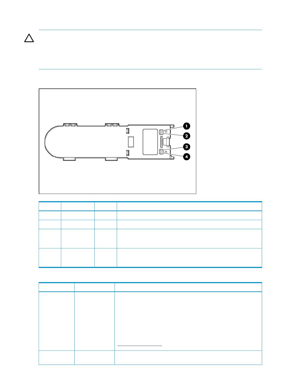
SPI board components
SPI (core I/O) board
DescriptionItem
BBWC module connections1
Serial peripheral interface board2
System battery3
System maintenance switch (SW6)
The system maintenance switch (SW6) is an eight position switch that is used for system
configuration. The default position for all eight positions is Off (closed).
FunctionSwitchDescriptionPosition
iLO 2 security is enabledOffiLO 2 security1
iLO 2 security is disabledOn
18 Component identification

FunctionSwitchDescriptionPosition
System configuration can be changedOffConfiguration lock2
System configuration is lockedOn
Reserved—Reserved3
Reserved—Reserved4
Password is enabledOffPassword protection override5
Password is disabledOn
Switch has no functionOffReset configuration6
ROM reads system configuration as invalidOn
See Table 1-1 (page 19) for details.POST LED switch 17
POST LED switch 28
Table 1-1 System Maintenance Switch Positions 7 and 8 Detail
Displayed on LED8–LED1Position 8Position 7
Port 85OffOff
Port 84OnOff
iLOOffOn
Embedded SAS statusOnOn
System maintenance switch (SW6) 19
System maintenance switch (SW1)
CAUTION: All supported AMD Opteron quad-core processors 3.1 GHz or greater and all
supported AMD Opteron six-core processors require the system maintenance switch, located on
the I/O backplane, (SW1) position 5 to be in the On position.
HP recommends updating to the latest version of firmware. Earlier firmware versions might not
validate the required switch setting for these processors.
Battery pack LEDs
DescriptionColorLEDItem ID
To interpret the illumination patters of this LED, see Table 1-2 (page 20)GreenBBWC status1
To interpret the illumination patters of this LED, see Table 1-2 (page 20)AmberBattery health2
This LED glows solid when 3.3 V auxiliary voltage is detected. The auxiliary
voltage preserves BBWC data and is available any time that the system
power cords are connected to a power supply.
GreenAuxiliary
power
3
This LED glows solid when the system is powered up and 12 V system
power is available. This power supply maintains the battery charge and
provides supplementary power to the cache microcontroller.
GreenSystem power4
Table 1-2 Battery health and BBWC status LED patterns
InterpretationLED 4 patternLED 3 pattern
The system is powered down, and the cache contains data that has not yet
been written to the drives. Restore system power as soon as possible to
prevent data loss.
Data preservation time is extended any time that 3.3 V auxiliary power is
available, as indicated by LED 2. In the absence of auxiliary power, battery
power alone preserves the data. A fullycharged battery can normally preserve
data for at least two days.
The battery lifetime also depends on the cache module size. For further
information, refer to the controller QuickSpecs on the HP website
(http://www.hp.com).
Flashing (1/2 Hz)
None
The cache microcontroller is waiting for the host controller to communicate.Double flash, then
pause
None
20 Component identification
/