Page is loading ...

Model TR40
Thermostat
with Serial RS232/485 Communications
Installation and Operation Manual
PN: 141-01070
Revision 03
Date: 5/22/03
Applies to these TR40 Revisions or later
Model Part Number Firmware Version
TR40-232 001-01070-07
TR40-485 001-01080-07
TS40 WDU 001-01060-07 3.05.5
HFR-232 CU 001-00810-07 3.04.3
HFR-485 CU 001-00820-07 3.04.3
*** IMPORTANT NOTICE ***
DO NOT USE THIS PRODUCT FOR BUILDING FREEZE PROTECTION! YOU ARE ADVISED TO INSTALL
A MECHANICAL FREEZE PROTECTION DEVICE ON YOUR SYSTEM FOR THIS PURPOSE.
RCS

DCN: 141-01070-03 TR40 Thermostat Manual 2
Residential Control Systems Inc.

DCN: 141-01070-03 TR40 Thermostat Manual 3
OPERATION
The TR40 Thermostat provides typical thermostat functions as well as the capability to send and receive
information via serial communications. This communications capability allows the thermostat’s setpoint,
mode and fan operation to be changed remotely. In addition, the remote systems can request status of the
thermostat’s temperature, setpoints, modes, and other system information.
The thermostat consists of two parts, a Wall Display Unit (WDU) and a HVAC Control Unit. The Wall
Display Unit looks like a traditional thermostat and is the wall mounted user interface for the TR40. It
provides display, control pushbuttons, and the temperature sensor. The WDU connects to the Control Unit
by a 4 wire cable. The Control Unit connects to the HVAC system in place of a standard thermostat and
provides thermostatic control of the system. In addition, the Control Unit sends and receives data and
commands via a twisted pair serial communications connection for remote control of the system.
The Model TR40 can be used with up to 4 remote temperature sensors such as the RS15.
TR40 Wall Display Unit
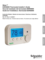
The WDU has a backlit LCD graphical display, control buttons, LEDs and a digital temperature sensor. The
WDU can display multiple screens. In the default thermostat screen, it shows the current temperature,
setpoint, mode and manual fan mode, time, outside temperature and other information.
Any changes in temperature, or control button operations, are transmitted to the Control Unit. Updates are
received from the Control Unit and displayed by the WDU.
Wall Display Unit Display
The TR40 display is a graphical LCD display capable of both text and graphics. The WDU has multiple
display “screens”. The main screen is the thermostat screen shown above. This screen has a “minimized”
mode in which only the temperature is displayed. It reverts to this minimized mode after a timeout delay
period.
Other standard screens are selected by the Menu button and include: Messages, Schedules, User Settings,
and Thermostat Info. Others may be present and selectable from the menu button in special versions of the
WDU.
TR40 WDU Thermostat Screen
75
MODE
FAN MENU
76 H
Econ
Sys Off
Run
No Msg
10:25
Outside 60
RUN
74 C
Indicator LEDs
Setpoint
Up/Down
Buttons
Function Control Buttons
Large Graphical
LCD Screen
On-screen
dynamic labels

DCN: 141-01070-03 TR40 Thermostat Manual 4
The TR40’s LCD features a backlit display for low light and night visibility. It can be set to remain on
constant or to turn out after a 20-45 second delay .

DCN: 141-01070-03 TR40 Thermostat Manual 5
OPERATION
Wall display Unit Control Buttons
All 6 buttons on the TS40 Wall Display Unit are “Soft Keys” meaning that they change functions when you
change screens. The function of the buttons is defined by “on-screen labels” that are dynamic and change
when you change screens. The following are definitions for the buttons for the main “Thermostat screen” and
their primary mode of operation. Other screens and their button operations are defined in following sections.
Wall Display Unit LEDs
The TR40 has four LED’s that display various status information. The LEDs have dynamic “on-screen” labels
that can change with the screen being displayed.
Wall Display Unit “Screens”
One of the unique features of the TS40 WDU graphical display is the ability to have multiple display screens.
In addition to a main thermostat screen, menus and other control screens for special functions are provided.
This makes an intuitive and easy to use “user interface”. It allows the many functions of the TR40 to be
easily navigated.
You move to other screens by pressing the Menu button from the main thermostat screen. A new Main
Menu “screen” will be displayed with a list of menu functions. When a menu item is selected, a new “screen”
will be displayed for that function. Refer to the individual screen descriptions that follow for details on
navigating each screen.
The Minimized Main Thermostat Screen
The main thermostat screen will go to a “minimized” screen after a timeout period. This presents a simple
uncluttered display of the current room temperature and outside temperature (if an OT sensor is attached).
Pressing any button causes the full Main Thermostat screen to be restored and displayed.
Screen Timeouts
When you menu to other screens, you have the option of exiting those screens to return to the main
thermostat screen or just waiting until the automatic screen timeout occurs that will return the display to the
main thermostat screen.
The main thermostat screen normally reverts to the minimized screen after 30 seconds. This can be
adjusted from 15 to 120 seconds in the User Settings Menu under Screen Timeout. You can also set the
timeout period to “0”. In this case the Main Thermostat screen will NEVER timeout and revert to the
minimized screen.

DCN: 141-01070-03 TR40 Thermostat Manual 6
Main Thermostat Screen
The main thermostat screen is the default display screen and is the screen that is normally displayed on the
Wall Display Unit. It will revert to a minimized screen after 30 seconds of display.
Temperature Display
The WDU will normally display the current temperature from the internal digital temperature sensor or a
remote sensor. The sensors have an accuracy of +/- 1°F(+/- .5°C). The WDU will display temperatures from
-63°F to 191°F. NOTE: If averaging remote sensors are attached, the display will show the average
temperature of the sensors.
Setpoint Display
The heating and cooling setpoints are displayed next to the Setpoint Up/Down buttons. In the HEAT mode,
the Up/Down buttons change the heat setpoint. In the COOL mode, they change the cooling setpoint. When
in AUTO mode, the buttons change the last call’s heating or cooling setpoint. Note that the setpoints will
“push” each other if they are adjusted to get within the minimum Heat/Cool separation (delta T) setting. This
is normally 3 degrees.
Clock Display
The current time is displayed in the upper left corner of the main screen.
Outside Temperature Display
The outside temperature is displayed in the top center of the main screen, if outside temperature information
has been sent to the thermostat or a remote temperature sensor is connected to the WDU.
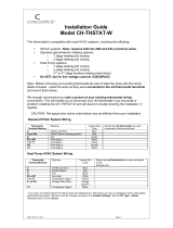
Main Thermostat Screen Buttons
UP and DOWN Buttons
The UP and DOWN buttons control the setpoint temperature.
75
MODE
FAN MENU
76 H
Economy
Sys Off
Run
No Msg
10:25
Outside 60
RUN
1
2
3
4
74 C

DCN: 141-01070-03 TR40 Thermostat Manual 7
Pushing the UP button will increment the setpoint value by one degree and conversely, pushing the Down
button will decrement the setpoint one degree. Pushing and holding a button down will cause the setpoint to
continuously change until the button is released.
Main Thermostat Screen
The setpoint can be set from 40°F to 99°F ( 5°C to 37°C), unless limited in the Installer Settings.
Main Thermostat Screen
MENU Button
The Menu button changes the screen display to the MAIN MENU screen which show what other functions
are available on the Thermostat. These are dynamic and can change with the version of the thermostat you
have, but the standard ones include:
Main Thermostat Screen
Menu Button
q Main Menu Screen
§ Messages
§ Schedules
§ User Settings
§ Thermostat Info
Main Thermostat Screen
MODE Button
The MODE button controls the HVAC system mode. The current mode selected is displayed above the
button. Pushing the MODE button will cause the mode and display to change to the next mode. The system
mode cycles from Off to Heat to Cool to Auto and back to Off again with each push of the MODE button.
When the HVAC system type is set to Heat Pump, the mode selection will include EH for Emergency Heat
mode.
Mode Button
§ Off
§ Heat
§ Cool
§ Auto
§ EH
Off Mode: System is off. No heating or cooling will come on.
Heat Mode: Only heating will occur.
Cool Mode: Only cooling will occur.
Auto Mode: Heating or cooling will come on according to the heating and cooling setpoints. The
system will automatically switch between heating and cooling when the temperature exceeds the
setpoints.
Note that you cannot lower the cooling setpoint below the heating setpoint. The thermostat will
“push” the heating setpoint lower if try to lower the cooling below the heating setpoint. It
maintains a 3 degree separation between the heating and cooling setpoint. The same is true for
RUN
AUTO
FAN
OFF
MODE
MENU
RUN
AUTO
FAN
OFF
MODE
MENU

DCN: 141-01070-03 TR40 Thermostat Manual 8
raising the heating setpoint above the cooling setpoint. Again the thermostat will “push” the
cooling setpoint up to maintain the 3 degree separation.
EH Mode: Only available when Heat Pump HVAC System type is selected. When there is a
compressor failure with the heat pump system, setting the mode to EH will allow the supplemental heat
to come on whenever there is a heat call to provide heating. It also disables the compressor outputs to
prevent further damage to the system.
Main Thermostat Screen
Main Thermostat Screen
FAN Button
The FAN button controls the HVAC system’s manual fan. The current manual fan mode is displayed above
the button. Normally this button is in the Auto mode. Pushing the FAN button once will turn the manual fan
operation On. Pushing it again will turn the manual fan off and return to the Auto mode (which means OFF
unless turned on by the furnace or AC). Changes in the fan mode are sent to the Control Unit.
Fan Button
§ Auto
§ On
Main Thermostat Screen
RUN/HOLD Button
The RUN/HOLD button controls the automatic schedule operation. In the HOLD mode, the current
temperature is maintained until changed by manual or remote network command. In the Run mode, the
schedule loaded into the thermostat is activated and setpoints will change according to the schedule and the
time and day of week. There is also an AWAY mode that you can select if you press and hold the button for
3 seconds. In the Away mode, preset Heating and Cooling setpoints are used.
Run Button
§ Run
§ Hold
§ Away
(Press and hold button)
Main Thermostat Screen LED Displays
The Main Thermostat screen has the following LEDs, numbered from top to bottom, 1-4.
o LED 1 Green: System Operation display.
o LED Off, “SYS OFF” displayed > HVAC system is OFF
o LED Off, “SYS MOT” displayed > Minimum Off Time (MOT) delay on is active
o LED On, “SYS ON” displayed > HVAC System is running
o LED On, “SYS MRT” displayed > Minimum Run Time (MRT) delay off is active
o LED 2 Green: System Economy Mode display
o LED OFF or On, “Econ” displayed > Economy or 1
st
stage heating or cooling only
o LED On, “2
nd
Stg” displayed > Stage 2 heating or cooling is active
o LED On, “3
rd
Stg” displayed > Stage 3 heating is active
RUN
AUTO
FAN
OFF
MODE
MENU
RUN
AUTO
FAN
OFF
MODE
MENU

DCN: 141-01070-03 TR40 Thermostat Manual 9
o LED On, “Vent” displayed > fresh air venting is active
o LED 3 Green: Run/Hold display. Shows state of Schedule Run/Hold Mode.
o LED Off, “Run” displayed > Schedule is running
o LED On, “Hold” displayed > Schedule is off, temperature setpoint hold in effect.
o LED 4 RED: Alert LED. Used for Messaging and other system alerts
o LED Off, “No Msg” displayed > No text messages or Alerts present
o LED On, Mail icon or Alert Text displayed > Message waiting or specific alert text
“Communications Error” Display
If the WDU is not properly wired or if communications to the Control Unit is interrupted, the LCD display will
display “Communications Failure” at the top center of the Main Thermostat Screen (where outside
temperature is normally displayed) . Momentary display of “Communications Failure” caused by loss of data,
will clear automatically when data communication is restored. If the “Communications Failure” display stays
on, check wiring or control unit for problems.

DCN: 141-01070-03 TR40 Thermostat Manual 10
Main Menu Screen
The TR40 Thermostat has a menu tree that can be accessed by pressing the “Menu” button on the Main
Thermostat screen. Various configurations of the TR40 can have different screen contents. The first screen
that will come up is the Main Menu screen that list the other menus or functions that can be accessed.
Standard screens are listed below.
Message Screen
This is a text messaging subsystem that allows message of up to 80 characters to be sent to the
thermostat. Message that are received are displayed when the message screen is selected.
Schedules Screen
This screen is used to set the programmable setback schedules of the thermostat.
User Settings
This screen is used to set the Clock, Screen Timeout, F/C mode and Sensor Calibration functions.
Sensor Calibration Screen
This screen is used to change the calibration of the thermostat to display the desired temperatures. Also will
allow calibration of any remote sensors attached to the thermostat.
Thermostat Info Screen
This screen shows the firmware versions of the WDU and Control Unit, HVAC system type and equipment
options, and the Network address.
Main Menu Screen navigation buttons:
Menu Selection
Messages
Schedules
User Settings
Thermostat Info
Done
Select
Done
Select
Return to Main Thermostat Screen
Select Menu Item
Scroll Up to next item
Scroll Down to next item

DCN: 141-01070-03 TR40 Thermostat Manual 11
Main Menu > Messages
The TR40 Message Screen allows you to retrieve text messages sent from the serial network to the
thermostat. The message screen features navigation buttons to read new and old messages and delete
them.
Up to 16 messages can be stored in the thermostat, if more than 16 messages are received, the oldest is
erased to make room for the newest message. New messages will turn on and flash the Message LED and
Mail Icon in the main thermostat screen.
Viewing messages makes them “old” and turns off the indicators. If you view some, but not all new
messages, the new message notification LED and icon will stay on. Messages are entered as most recent
message as number 1 message.
Message Screen
Message Screen navigation buttons:
When you first select the Message Screen, the most recently received message will be displayed as
Message 1. If other messages are stored in memory, they can be recalled and viewed or deleted by using
the message memory navigation buttons.
Messages
Message 1 10/14 5:35 PM
The TR40 can receive 16 text
messages, each up to 80 characters
long. They are date/timed stamped.
Done
Del
Prev
Next
Next
Done
Del
Prev
Return to Main Menu Screen
Delete the Message being displayed
Display previous message. Scroll up in message stack
Display next message. Scroll down in the message stack

DCN: 141-01070-03 TR40 Thermostat Manual 12
Main Menu > Schedules
The Schedules Screen allows you to review and set the setback schedule for the thermostat. The TR40 has
4 x 7 schedule. Four times a day can be selected for Heating and Cooling setpoints. Each day of the week
can have a different schedule. Groups of days can be copied with the same schedule. When the TR40 is
set to “Run” mode, the schedule will be executed daily, with the setpoints being changed as per that days
schedule stored in the thermostat. “Hold” mode stops schedule operation and holds the current setpoints
until changed manually or by network commands.
The schedules Screen gives you the option of setting an custom setback schedule or to load one of two
preset schedules.
Menu Options
• Heat and Cool: You can change the individual day/hour and setpoints for the Heat and Cool
schedule by selecting this menu item.
• Preset: Comfort: This is a preset schedule with mild setbacks. Select this menu item to load the
Comfort schedule into the thermostat.
• Preset: EnergyMiser: This is a preset schedule with deeper setbacks. Select this menu item to
load the Energymiser schedule into the thermostat.
Schedules Screen
Select Schedule
Heat and Cool
Preset: Comfort
Preset: EnergyMiser
Done
Select
Done
Select
Return to Main Menu Screen
Select the schedule to view or modify

DCN: 141-01070-03 TR40 Thermostat Manual 13
Main Menu > Schedules > Heat and Cool Schedule Screen
When you select the Heat and Cool Schedule menu item, the Schedule programming screen opens and the
schedule for current day will be displayed. Use the scroll buttons to highlight the data to be modified. Once
the data has been highlighted, use the +/- buttons to change the value of the data.
To copy a days schedule to another or group of days, move the cursor to “c” on the bottom right of the
schedule screen. When you highlight “c”, the button below will become “Copy”. Press this button to change
to the Copy Schedule Screen.
Schedule Screen navigation buttons:
Monday Schedule
Time Heat Cool
Morn 6:00 A 72 82
Day 9:00 A 68 84
Eve 5:00 P 74 76
Nite
10:00 P 70
78
Done
Next
+
_
c
Done
Next
+
Copy
Return to Main Menu Screen
Scroll Back
Scroll Forward
Select the next Day schedule
OR if the copy “c” is selected, go to copy schedule screen.
Increase the time or temperature selected
Decrease the time or temperature selected

DCN: 141-01070-03 TR40 Thermostat Manual 14
Main Menu > Schedules > Heat and Cool > Copy Schedule
The Copy Schedule screen is a sub screen of the Schedule screen. The Copy Schedule screen allows you to
copy a day’s schedule to another day or group of days.
First select the day to be copied in the Schedule screen. Scroll to the “c” at the bottom of the Schedule
screen to highlight it. The “Next” button will change to the “Copy” button. Press the “Copy” button to open
the Copy Schedule screen.
Scroll through the days and select the days the schedule is to be copied to by setting the “N” under each day
to “Y” by using the Yes/No buttons.
After selecting all the days desired, press the “Copy” button.
Exit the Copy Schedule screen with the “Back” button.
Copy Schedule Screen
Copy Schedule screen navigation buttons:
Copy Monday Schedule
to
Sun Tue Wed Thu Fri Sat
N Y Y Y Y N
Back
Copy
Yes
No
Return to Schedule Screen
Move back with selection bar
Move forward with selection bar
Copy the schedule to the selected days
Copy schedule to this day
Do not copy schedule to this day
Back
Copy
Yes
No

DCN: 141-01070-03 TR40 Thermostat Manual 15
Main Menu > User Settings
The User Settings screen allows you to set or change various user options of the thermostat such as the
clock, timeouts, Fahrenheit/Celsius mode or sensor calibration.
Menu options:
• Set Clock
Select this menu item to go to the Clock setting screen.
• Screen Timeout
This sets the time before the current screen times out and returns to the minimized screen. If the time is
set to 0, the current screen will not time out and will stay displayed until another screen is selected.
Options are 0, 15-127 seconds. Select menu item and adjust value with +/- buttons.
• F/C Select
Select which temperature display mode you desire, Fahrenheit (F) or Celsius (C) with +/- buttons.
• Sensor Calibration
Select this menu item to go to the Sensor Calibration screen.
• Backlight Timeout
The LCD backlight can be always on or set to timeout and go off after a preset timeout time. The timeout
time can be adjusted from 0 (always on), or 20 to45 seconds before going off. Use +/- buttons to set time
desired. Default set to 30 seconds.
User Settings
Set Clock
Screen Timeout 60
F/C Mode F
Sensor Calibration
Done
Select
Done
Select
Return to Main Menu
Increment value
Decrement value
Select the function to be set
+
_
+
_

DCN: 141-01070-03 TR40 Thermostat Manual 16
Main Menu > User Settings > Set Clock
The Set Clock screen allows you to set the system clock.
To set the Time and Day, move the cursor with the navigation arrows until the data you want to change is
highlighted.
Using the + and – arrows to increment or decrement the data to the desired setting.
When finished, press the SET button to return to the Main Menu screen or wait for screen to timeout.
NOTE: If the clock has been reset by an extended power outage, the Clock display on the thermostat
screen will be blinking. Pressing the MENU button will take you directly to this screen to set the clock.
Set Clock Screen
Set Clock Screen navigation buttons:
Set Clock
Time 12:00 PM
Date 7/13/03
Day Thu
Set
+
_
Not Used
Move back with selection box
Move forward with selection box
Set the time
Increment Time/Day
Decrement Time/Day
Set
+

DCN: 141-01070-03 TR40 Thermostat Manual 17

DCN: 141-01070-03 TR40 Thermostat Manual 18
Main Menu > User Settings > Sensor Calibration
The Sensor Calibration screen allows you to change the temperature calibration for the internal and any
external remote temperature sensors attached to the TR40 WDU. You can change the temperature
calibration by +/- 7 degrees.
When the Sensor Calibration screen is selected it will show the internal and all detected remote sensors.
Each sensor found will show the current temperature ((75) in the example screen below) and the current
number of degrees of offset being applied (1 deg in the example). N/a means that no remote sensor is
attached. If the sensor’s actual temp is (74) with 0 degrees of offset and you want it to be 75, then press +
to add 1 deg and it will show (75).
To change the temperature calibration, use the scroll buttons to select the internal or a remote sensor. Once
selected, use the + and – buttons to change the temperature calibration to the desired setting.
The value shown in the (xx) is the calibrated or offset temperature that you want the sensor to show.
Sensor Calibration Screen
Sensor Calibration navigation buttons:
Sensor Calibration
Internal (75) 1
Remote 1 n/a 0
Remote 2 n/a 0
Remote 3 n/a 0
Done
+
Done
+
Return to Main Menu Screen
Increase the temperature by 1 deg
Decrease the temperature by 1 deg
Not used
Scroll Up
Scroll Down

DCN: 141-01070-03 TR40 Thermostat Manual 19

DCN: 141-01070-03 TR40 Thermostat Manual 20
Main Menu > Thermostat Info
The Thermostat Info screen displays the current configuration of the Thermostat Wall Display Unit and the
HVAC Control Unit. This information is useful for quick check of firmware versions and HVAC system setup.
It also shows the network address setting.
Thermostat information displayed is:
• Wall Display Unit Type and Firmware version number.
• Control Unit Type and Firmware version number.
• System Type setting: Standard or HP HVAC system
• Fan Type setting for Standard systems: No Fan w/heat (Gas systems) or Fan w/heat (Electric systems)
OR
• Changeover setting for Heat Pump systems: Changeover with cool or changeover with heat.
• Network address setting: 1-254 valid
When finished viewing this screen press the Done button to return to the main Menu screen or wait for
screen to timeout.
Thermostat Info Screen
Thermostat Info Screen navigation buttons:
Thermostat Info
TS40R Ver: 03.05.5
Controller Ver: 03.04.3
System Type: Standard
Fan Type: No Fan w/HT
Network Address: 01
Done
Done
Return to Main Menu screen.
/