Page is loading ...

X-10 Thermostat
Standard Model TX15
Bi-directional Model TX15-B
Remote Sensor Model TX15R
Remote Sensor Model TX15R-B
INSTALLATION AND OPERATION MANUAL
Applies to the following revisions or later:
TS15 WDU Rev 07
HCXB HVAC CU Rev 03
HCXP HVAC CU Rev 03
HCXE HVAC CU Rev 03
HCXL HVAC CU Rev 03
(PCB Rev E)
DCN: 141-00410 Rev 05
4/00
*** IMPORTANT NOTICE ***
DO NOT USE THIS PRODUCT FOR BUILDING FREEZE PROTECTION! YOU ARE ADVISED TO
INSTALL A MECHANICAL FREEZE PROTECTION DEVICE FOR THIS PURPOSE.
RCS
Residential Control Systems Inc.

DCN: 141-00410-05 4/00
2
1. TX15 OPERATION
The TX15 series thermostats provide typical thermostat functions as well as the capability to receive X-10
powerline carrier signals. The X-10 commands allow for the thermostat’s Setpoint, Mode and Fan
functions to be changed remotely. In addition, the TX15-B series has bi-directional capability and can also
transmit information by X-10 commands using an extended X-10 command set.
The TX15 thermostats consist of two parts, a
Wall Display Unit (WDU)
and a
Control Unit
. The Wall
Display Unit looks like a traditional thermostat and is the wall mounted user interface for the TX15 series.
It provides display, control pushbuttons and the temperature sensor. The WDU connects to the Control
Unit by a 4 wire cable. The Control Unit connects to the HVAC system in place of a standard thermostat
and provides the thermostatic temperature control of the system. The Control Unit also has the X-10
interface input and the 12 VDC power supply input.
TS15 Wall Display Unit
The WDU has a two digit back-lit LCD display, control buttons for changing the Setpoint (Up and Down),
Mode (Off, Heat, Cool, Auto) and manual Fan (On/Auto) functions and a digital temperature sensor. The
LCD display serves as a common display for current temperature, setpoint, mode and manual fan status.
The display normally shows current temperature and switches to show setpoint or mode when those
buttons are pushed. Remote sensor versions do not have an internal sensor and have a connection for a
remote sensor, such as the RS15 wall mounted temperature sensor.
Any changes in temperature, or control button operations, are transmitted to the Control Unit. Updates in
setpoint or mode can also be received by the WDU from the Control Unit. When updates are received,
they are displayed for 3 seconds and then the display returns to the current temperature.
LCD Display
The LCD display normally shows the current temperature. Whenever any of the control buttons are
pushed, the LCD display will change to show that function’s current status. The LCD display will stay in
the new display mode as long as buttons are being pushed. After 3 seconds of no activity, the display will
change back to show current temperature. The right decimal point on the LCD display will turn on
whenever manual fan is on. The left decimal point will blink whenever the setback mode is active.
Remote changes in setpoint or modes that are received from the Control Unit will cause the LCD display to
switch and display the updated data for 3 seconds and then return to current temperature.
Control Buttons
The
UP
and
DOWN
buttons control the setpoint temperature. Pushing the
UP
or
DOWN
button once will
cause the LCD display to change to show the
current setpoint temperature
. Pushing the button again
(before the display switches back to current temperature) will decrement or increment the setpoint value by
one degree. Pushing and holding a button down will cause the setpoint to continuously change until the
.7.5
MODE
FAN
SETPOINT INCREASE BUTTON
SETPOINT DECREASE BUTTON
SYSTEM MODE BUTTON
MANUAL FAN BUTTON
MANUAL FAN ON INDICATOR
LCD DISPLAY - SHOWS
CURRENT TEMP NORMALLY.
SETPOINT OR MODE WHEN
BUTTONS PUSHED.
SETBACK MODE ON INDICATOR
TS15 WDU

DCN: 141-00410-05 4/00
3
button is released. After 3 seconds of no activity, the LCD display will change back to show the current
temperature and the new setpoint value will be transmitted to the Control Unit.
The setpoint can be set from 40
F to 99
F ( 5
C to 37
C).
There is only
ONE
setpoint for the WDU, and it is used for both heating and cooling. The displayed
setpoint shows the setpoint of the
current mode
of the system. If you change modes, this same setpoint
will be used for the new mode, unless otherwise changed by local (buttons) or remote updates.
MODE
The MODE button controls the HVAC system mode. To see what mode the HVAC is in, push the MODE
button once and the LCD display will change to show the current mode. Pushing the
MODE
button again
while the MODE is being displayed, will cause the mode and display to change to the next mode. The
system mode cycles from
Off
to
Heat
to
Cool
to
Auto
and back to
Off
again with each push of the
MODE
button. Any change in the system mode is transmitted to the Control Unit.
When HP system type is selected on the Control Unit, an additional system mode of “
EH”
, or Emergency
Heat, is included in the TS15 mode selections. EH is used when Heat Pump compressor failure requires
the use of Auxiliary Heat (heat strips) for primary heating. When EH mode is selected, the display will
alternate between current temperature and “EH” to remind you that the EH mode has been selected.
FAN
The
FAN
button controls the HVAC system’s manual fan. Pushing the
FAN
button once will turn the fan
On and pushing it again will turn the fan to the Auto mode (OFF unless turned on by the furnace or AC).
The right decimal point of the LCD display will come on when the manual fan is ON. Changes in the fan
mode will be transmitted to the Control Unit.
Temperature Display
The WDU will normally display the current temperature from the internal digital temperature sensor or a
remote sensor. The sensors have an accuracy of +/- 1
F(+/- .5
C) for the range of -67
F(-55
C) to
257
F(125
C). The WDU will display temperatures from 0
F/C to 127
F/C. Temperatures less than 0
will
be displayed as 00, temperatures over 100 will be displayed without the leading 1 (example: 102 as 02.)
Temperature Display Calibration
The TS15 and TS15R Wall Display Units have the capability for the user to adjust the calibration of the
unit from the front panel. If you desire to change the displayed temperature calibration, you may do so by
adjusting the Calibration Offset.
What you are adjusting.
You are adjusting a calibration
OFFSET
. This allows for the temperature
measured by the WDU to be added or subtracted by an offset of 0 to + or - 7 degrees.
When in the Calibration Mode, the LCD screen will be displaying a number from 0 to +/- 7. This is the
current calibration offset. The factory default is usually ”0” but may be set to a factory offset also.
For instance, if the display shows 70 degrees and the desired temperature display is 72 degrees, you
would change the calibration offset by increasing it 2 degrees. If the offset was 0 degrees, then the new
offset would be 2 degrees and this is what is displayed on the calibration offset display.
If the displays shows 70 degrees and the desired temperature display is 68 degrees, you would change
the calibration offset by decreasing it 2 degrees. If the offset was 0 degrees, then the new offset would be
–2 degrees.
Remember: what you are changing is a number from 0 to +/- 7.

DCN: 141-00410-05 4/00
4
How to enter the Calibration Mode and view the Calibration Offset.
To enter into the calibration mode, FIRST press and HOLD the “MODE” button and then simultaneously
press the “FAN” button until “CO” appears on the LCD display.
Release the buttons and the current calibration offset number will appear on the LCD display. This is
usually “0” but may be any number from 7 to –7.
When viewing the calibration offset only and you do not change it, the display will automatically revert back
to current temperature display after 20 seconds of no activity.
How to change the Calibration Offset.
Enter into the calibration mode as described above. This will display the current Calibration Offset.
Determine how many degrees you want to change the temperature calibration, a maximum of + or – 7
degrees.
Adjust the Calibration Offset by pressing the UP or DOWN buttons. Each button press increments the
offset by 1 degree. You will see the offset displayed on the LCD screen.
When you are done with adjusting the calibration offset, the WDU will automatically store the new offset
and return to the current temperature screen after 3 seconds of no activity.
The new temperature offset will be calculated and displayed on the next temperature update cycle.
It may be several seconds before you see the temperature change.
WDU “CF” Error Display
If the WDU is not properly wired or if communications to the Control Unit is interrupted, the LCD display
will display “CF” to denote communication failure. Momentary display of “CF” caused by bad or lost data,
will clear automatically when data communication is restored. If the “CF” display stays on, check wiring for
problems. A continuous “CF” display may indicate a problem with the Control Unit or the WDU itself.
To verify WDU operation, replace the unit with another known good unit.
TX15 CONTROL UNIT
The TX15 Control Unit works in conjunction with the Wall Display Unit to provide thermostatic control of
the HVAC system. In addition, the Control Unit can receive X-10 commands for remote control of the
setpoints, temperatures and modes of the thermostat. The bi-directional TX15-B unit also transmits
information via X-10 commands.
The TX15 Control Unit connects to the HVAC system the same as, and in place of, a standard thermostat.
The Control Unit works with either standard Gas/Electric or Heat Pump HVAC units.
Actual thermostatic control of the HVAC system is provided by the Control Unit. Changes in the current
temperature, setpoint, system or fan modes are sent to the Control Unit either from the WDU or via X-10
commands. The Control Unit monitors this information and operates the HVAC system accordingly.
Standard HVAC Systems Operation
In the
HEAT
mode, the heating system will be turned on at one degree below the setpoint and will turn off
at
the setpoint. In the
COOL
mode, the cooling system will be turned on at one degree above the setpoint
and will turn off
at
the setpoint. In the
AUTO
mode, the current heating or cooling operating mode will
operate as usual with the one degree setpoint control. In order for the system to change operating mode
from heating to cooling, the temperature must rise two degrees above the setpoint. On subsequent calls
after a change over has occurred, the system will operate normally with the one degree setpoint control.

DCN: 141-00410-05 4/00
5
This changeover difference of two degrees on the first call helps to prevent the system from
overshooting and oscillating between heating and cooling. Changes from cooling to heating works
similarly, with the two degree changeover difference being two degrees below the setpoint.
Standard System Mode Selection
. To set the Control Unit for standard GAS/ELECTRIC operation,
leave the dipswitch SW1-1 set to the STD SYS position (OFF-default).
Fan Mode Selection
. Normally, GAS heating systems DO NOT require fan calls along with the heat call
due to thermoswitch fan operation in the furnace. For Gas systems, dipswitch SW1-2 should be set to the
STD FAN position (OFF). Electric and hydronic heating systems generally DO require that a fan call be
generated along with the heat call. For these systems, dipswitch SW1-2 should be set to the FAN/HEAT
position (ON). Be sure to check your HVAC system’s requirements.
Minimum Run Time.
The Control Unit has a minimum runtime in either heating or cooling of 4 minutes.
The system will continue to operate
even if the setpoint is satisfied or changed
until MRT time-out. If
the system mode is changed to off, the minimum run time is canceled and the system will go off
immediately.
Short Cycle Protection (SCP) Delay
. The Control Unit has a short cycle protection (SCP) delay of 5
minutes after any compressor operation. This delay prevents a subsequent compressor call until the delay
times out. This delay is to allow the compressor head pressure to bleed off before starting again. The
SCP is active in either STD or HP modes. In the Heat Pump mode, it effects both heating and cooling
cycles.
The Status LED on the Control Unit circuit board will blink twice during SCP delay periods.
Heat Pump HVAC System Operations
The heat pump system mode works similarly to the standard systems. Normal heating/cooling calls and
auto-changeover function the same as standard systems. In addition, Heat Pumps have a second stage
of heating. Heat pump systems use the compressor for the primary heating/cooling source. During
periods of high heating requirements, additional heat stages, usually electric strip heaters, may be used.
These second stages of heating will be turned on when the current temperature falls four degrees below
the current setpoint and will turn off when the difference is reduced to two degrees below the current
setpoint.
Heat Pump Mode Selection.
For Heat Pump operation, set SW1-1 to the HP SYS position (ON).
Fan Mode Selection.
Set the Fan selection, SW1-2, to the STD FAN position (OFF).
Change Over Selection. Heat pump systems change from heating to cooling by reversing the direction of
Freon flow in the system. This change over is controlled by the change over (sometimes referred to as
reversing valve) output from the Control Unit. Most heat pump systems are designed to work normally in
the heating mode and require a change over output for cooling. Set dipswitch SW1-3 to the CO/CL
position (OFF-default) for this type system. Check your HVAC system requirements for correct settings. If
your system requires change over with heating, set SW1-3 to the CO/HT position (ON). After the change
over relay output is first activated, it will stay on continuously even when there is no call until it is turned off
by changing to the opposite mode. This prevents continuously cycling of the reversing valve with each call
as a system is generally in heating or cooling mode for extended periods.
Emergency Heat Mode.
When the Control Unit is selected for a
Heat Pump system, there is an
Emergency Heat Mode that can be enabled from the WDU mode selection. In the event of a compressor
failure, the “EH” mode can be selected. When in this mode, the second stage heating (heat strips) will be
used for stage one heat calls. This mode is for temporary use until the compressor can be repaired.
Fahrenheit or Centigrade Selection
Fahrenheit or Centigrade mode is selected by dipswitch SW1-4. In the OFF position, Fahrenheit mode is
selected. Set SW1-4 ON to select Centigrade mode. This sets the mode for both Control Unit and WDU.

DCN: 141-00410-05 4/00
6
Status LED
The Control Unit has a Status LED on the circuit board that will normally blink on and off slowly as a
system heartbeat. During short cycle protection delay periods, the LED will blink twice for each heartbeat.
This indicates that the compressor is locked out during this time.
X-10 Interface
The TX15 Control Unit has an X-10 powerline carrier interface that allows X-10 commands to be received
over the 110 VAC powerline. Commands from remote systems can change the setpoint temperature and
mode of the Thermostat. The Control Unit connects to the power line by an external PSC05 X-10
Interface Module. X-10 commands received by the Control Unit are decoded to a new setpoint or a new
mode and are sent to the WDU to update its display. When X-10 commands are received, the WDU will
switch it’s display to show the updated information for three seconds and then return to the current temp
display.
TX15-B Thermostats also transmit information by X-10 commands.
The Thermostat has an X-10 address called a House Code. These 16 house codes are letters from A to P
and can be set by dipswitch SW1.
X-10 House Code Setting
The TX15 House Code address, A to P, is set by dipswitch SW1, positions 5, 6, 7 and 8. Set the desired
house code by the following table. For easy testing, use house code J, which is ALL OFF on the
dipswitch positions 5 - 8.
X-10 Commands
The TX15 thermostats respond to X-10 commands to change setpoints and modes of the unit. The
specific X-10 commands that the TX15 Control Unit can receive and how they are decoded into setpoints
and modes is defined in a “Decode Table”.
The Decode Table included with this unit is described in APPENDIX A.
For TX15-B bi-directional X-10 Thermostats, a separate software manual is included and describes the bi-
directional X-10 commands.
X-10
HOUSE CODE
SW1 SETTING
HC1234
A 1001
B 0001
C 1101
D 0101
E 1110
F 0110
G 1010
H 0010
I 1000
J 0000
K 1100
L 0100
M 1111
N 0111
O 1011
P 0011
OFF - ON
0 - 1
X-10
HOUSE
CODE
SW1
1 0 0 1
HC1
HC2
HC3
HC4
= House Code A
1 STD/HP
Example House Code
2 FAN/HT
3 CO C/H
4 F/C SEL
5 HC1
6 HC2
7 HC3
8 HC4

DCN: 141-00410-05 4/00
8
2. TX15 INSTALLATION
Before proceeding with removing an existing thermostat and installing the TX15,
Read the following important steps.
1. Record existing wiring information on the enclosed wiring form.
2. Perform the TX15 bench test in Section 3
3. Check WDU wiring BEFORE applying power to control unit.
4. Be sure to install a freeze protection device as required.
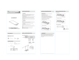
Installation Overview
Standard thermostat wiring vs TX15 in retrofit applications.
Heating &
Cooling
System
4, 5 or 6 wires
18Ga thermostat wiring
4 Wires Required
TX15
Control
Unit
Heating &
Cooling
System
TX15
Wall Display
Unit
Thermostat
Replace
Thermostat with
Wall Display Unit
Insert Control Unit into
the thermostat wiring
4,5 or 6 wires
as original
installation
OLD
NEW
STOP
Freeze Protection.
In cold climates that require the heating system to be used for building freeze protection, a mechanical
backup freeze protection device MUST be installed on the heating system. This can be a simple
mechanical heating thermostat or a pres
et thermoswitch installed in the heated area.
Heating
System
Red Wire 24VAC R
White Wire Heat W
40-45
R
W
Thermostat connections
Wire across Heater R/W terminals in addition to Control Unit wiring.
Mechanical
Thermostat or
Thermoswitch

DCN: 141-00410-05 4/00
9
TX15 Wall Display Unit Installation
WDU Location
Choose a location that best represents the temperature of the area to be controlled.
Avoid locations that are subject to drafts, from doors and windows, or areas with direct sunlight exposure.
WDU Mounting
Route the wires to the WDU through the access hole in the back of the case. Mount the
WDU to the wall with the screws and anchors provided. Be sure to plug any large access hole in the wall
with sealer or insulation to prevent wall drafts from affecting WDU operation.
WDU Prewiring
The recommended wiring to the WDU from the Control Unit should be a two twisted pair
cable, 24 Ga minimum. Cat 5, 4 pair cabling is acceptable. In retrofit applications the existing thermostat
wiring (a least 4 wires) may be adequate. However, such non-twisted wiring may be subject to
interference due to noise from adjacent wiring or other sources.
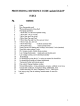
Wiring to the Wall Display Unit
Remote Sensor
TS15-R WDU’s have an addition connector, J2, on the WDU base for connection of an external remote
temperature sensor. Follow the wiring diagram with the remote sensor to connect to the WDU.
G
+12
C
D
1 POWER GND
2 POWER +
3 COM CLOCK
4 COM DATA
WIRING
ACCESS
HOLE
J1
WDU WIRING DIAGRAM
TS15 WDU
BASE
Hook TOP here
and rotate into
base. Be sure
pins engage in
connector ok.
TO CLOSE
OPENING AND CLOSING THE WDU CASE
TO OPEN
PULL FROM LOWER CORNERS
OPEN
CLOSE
BASE
For Remote Sensor Versions
G
+5
C
D
J2
TX15 CONTROL UNIT
GND G
+12VDC +V
CLOCK C
DATA D
WDU
+12V
GND
DATA
CLK
TWISTED PAIR 22 GA WIRE RECOMMENDED
TX15 WALL DISPLAY UNIT
J1
** CAUTION **
DO NOT
MISWIRE WDU
CONNECTIONS
OR
DAMAGE WILL
RESULT

DCN: 141-00410-05 4/00
10
TX15 CONTROL UNIT INSTALLATION
Location and Mounting.
Install the TX15 Control Unit in a protected, convenient, INDOOR location near
the HVAC system or in a service accessible area such as an equipment closet or garage.
Mount the Control Unit in a vertical position on a wall or sturdy structural member. The unit may be
mounted on the HVAC system but care should be taken to avoid the hot burner section or high vibration
areas.
CONTROL UNIT WIRING
HVAC System Connection.
Electrically, the Control Unit looks like a standard thermostat to your HVAC system. All connections to the
HVAC systems are made at the normal thermostat connections on the HVAC unit.
Refer to the following HVAC wiring information for the type of HVAC system, Standard Or Heat Pump, that
the Control Unit is being connected to. Refer to your HVAC system’s documentation for specific
information on its thermostat connections.
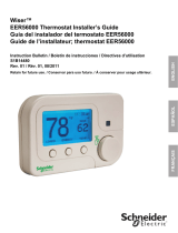
Standard Gas/Electric HVAC System Wiring
Heat Pump HVAC System Wiring
Standard HVAC System
G FAN
W HEAT
Y COMPRESSOR
R 24VAC RETURN
C 24VAC COMMON
RED
GREEN
WHITE
YELLOW
RH
W HEAT
G FAN
Y1 COMP
O C/O
HVAC
SYSTEM
THERMOSTAT CONNECTION
TX15 Control Unit
TYPICAL THERMOSTAT
WIRING COLOR CODES
NOT USED
RC
24VAC
IMPORTANT!
Install jumper for
common transformer
systems (normal).
J5
HEATPUMP HVAC System
G FAN
W2 SECOND STAGE HEAT
Y COMPRESSOR
R 24VAC RETURN
C 24VAC COMMON
RED
GREEN
WHITE
YELLOW
RH
W HEAT
G FAN
Y1 COMP
O C/O
HVAC
SYSTEM
THERMOSTAT CONNECTION
TX15 Control Unit
TYPICAL THERMOSTAT
WIRING COLOR CODES
O CHANGEOVER
RC
24VAC
J5
ORANGE
IMPORTANT!
Install jumper for
common transformer
systems (normal)

DCN: 141-00410-05 4/00
11
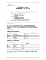
Wiring to the PSC05 X-10 Interface Module
The X-10 interface on the Control Unit is the RJ11 jack, J2. It is connected to an X-10 power line interface
module, Model PSC05, by the
four (4) wire
modular phone cable provided.
IMPORTANT NOTE: Use the Modular Cable Provided. If you do not, be sure the cable is the correct
type. The Cable must be 4 wire (NOT 2), and not reversing.
If you are having X10 communication problems or in doubt about the cable, check the cable with the
simple inspection shown below.
Power Connection
The TX15 Control Unit requires 12VDC, 200ma max. Power is provided by an external transformer
connected to jack J4. (Caution, center ground plug-ins transformers only).
RJ11
JACK
X10 I/O
PSC05
X-10 I/O
MODULE
4 WIRE MODULAR CABLE
Place the ends of the cable
side by side and verify the
color codes of the
conductors are in reverse
order as shown here.
B R G Y
B R G Y
INCORRECT CABLE WIRING
DO NOT USE THIS CABLE
TX15 CONTROL UNIT
J2
120V OUTLET
B R G Y
OR
Y G R B
Y G R B
OR
B R G Y
COR
RECT CABLE WIRING

DCN: 141-00410-05 4/00
12
3. SYSTEM CHECKOUT
It is strongly recommended that you hook-up and run a simple bench test before installing the TX15. Not
only will this save you time in system checkout but will also familiarize you with the thermostat’s operation.
THERMOSTAT BENCH TEST
NOTE: Remote sensor versions REQUIRE the remote sensor to be connected to the WDU in order
to work. You cannot test the system without the remote sensor attached.
1. Connect the Wall Display Unit to the Control Unit with a short (12 inch) 4 wire cable.
2. Before power up, set the Control Unit dipswitch, SW1, to ALL OFF
3. Connect the 12VDC transformer to the Control Unit.
4. Plug the transformer into a 110VAC outlet and apply power. Verify Control Unit Status LED is blinking.
5. Verify the WDU display comes on and shows the current temperature.
a. If no display and backlights are not on, check wiring and power at the Control Unit.
b. If no display but backlights are on, check to be sure you don’t have a remote sensor version
without sensors attached.
c. If a “CF” display is shown on the WDU, double check your wiring to the control unit.
d. Do not proceed until the current temperature is displayed on the WDU.
6. With the current temperature displayed on the WDU, we have verified communication between it and
the Control Unit is OK. Any communication problems will result in a “CF” (Communications Failure) display
on the WDU.
7. Press the Fan button on the WDU. The Control Unit’s Fan LED and relay should turn on.
8. Press the Fan button again. The Fan LED and relay should turn off.
9. Press the Mode button until the WDU is showing “H” for Heat Mode.
10. Press the Setpoint Up button until the setpoint is above the current temperature. The Heat LED and
relay should come on.
11. Press the Mode button until the WDU is showing “O” for OFF. The Heat LED and relay will turn OFF.
12. Press the Mode button until the WDU is showing “C” for Cool Mode.
13. Press the Setpoint Down button until the setpoint is below the current temperature. The Cool and Fan
LEDs and relays should turn on.
14. Press the mode button until the WDU is showing “O” for OFF Mode.
15. All LEDs and relays should turn off.
16. When you have successfully completed all these tests, you have verified that the TX15 is working
correctly.
X-10 QUICK TEST
Requires an X-10 PRO Mini-Controller (PHC01), Maxi-Controller (PHC02) or other known good source of
X10 signals.
1. With the TX15 connected as above, proceed with connecting the PSC05 X-10 Interface Module.
2. Connect a four wire modular phone cable to the Control Unit.
3. Connect the other end of the cable to the PSC05 X-10 Interface Module.
4. Plug the PSC05 X-10 Interface Module into a 110VAC outlet.
5. Plug an X-10 Controller in the outlet.
6. Set the House Code on the X-10 controller to match the TX15 Control Unit (House Code J).
7. Send Unit code ON and OFF commands from the X-10 controller and verify that the WDU display
shows the correct response to each command sent per the X-10 Decode Table in Appendix A.
8. If you have difficulty receiving X-10 commands, double check the modular cable, the X-10 Interface
Module and the House Code settings.
NOTE: The LED on the PSC05 Interface Module should blink
with each command sent from the X-10 controller.
9. If the TX15 responds properly to the X-10 commands, proceed with installation.
It is recommended that you install the TS15 and then rerun these quick tests BEFORE you connect the
controller to the HVAC system. You will be confident that the TS15 is working correctly before you attempt
to interface to the HVAC system.

DCN: 141-00410-05 4/00
13
HVAC SYSTEM TESTING
The TX15 Control Unit connects to the HVAC system at the normal thermostat connections on the HVAC
unit. Standard thermostat control of HVAC systems consist of 24VAC contact closures in the thermostat.
You can verify that your HVAC system is working correctly by duplicating the contact closures by shorting
across the proper terminals at the HVAC system’s thermostat connection. Refer to the following HVAC
system example.
HVAC System Example
You can also verify the HVAC operation at the TX15 Control Unit by placing
a wire jumper across the Control Units HVAC System terminals as follows
(with the HVAC system connected to theTX15):
For Standard HVAC systems, jump across J4, HVAC System terminals as follows:
FAN operation: Jumper across R and G (Fan) terminals.
HEAT operation: Jumper across R and W (Heat) terminals (Fan is not usually necessary for gas furnaces).
COOL operation: Jumper across R and Y (Compressor) and G (Fan) terminals.
For Heat Pump systems with Changeover for cooling, jump across J4, HVAC System terminals as follows:
FAN operation: Jumper across R and G terminals.
HEAT Stage 1 operation: Jumper across R and Y (Compressor) and G (Fan) terminals.
HEAT Stage 2 operation: Jumper across R and W (Heat Strips) and G (Fan) terminals.
COOL operation: Jumper across R and Y (Compressor) and O (Change Over) and G (Fan) terminals.
If the Control Unit’s output LEDs are ON and you suspect you are not getting an output from the relays,
perform the above shorting test to verify that the HVAC system is working OK. If the HVAC system
responds correctly to the shorted terminals, then the output relay is suspect.
B 24VAC COMMON
R 24VAC HOT
G FAN
W HEAT
Y COMP
HVAC SYSTEM
STANDARD GAS/AC
FAN
RELAY
GAS
VALVE
COMP
RELAY
24VAC
Simplified diagram of an HVAC System and Thermostat.
The Thermostat operates like switches to control the
HVAC’s Heat, Cool and Fan functions.
FAN
HEAT
COMP
OUTDOOR
CONDENSING
UNIT
FURNACE AND BLOWER UNIT
TYPICAL THERMOSTAT
Thermostat
Connection
To verify the HVAC system is working properly you
can simulate the thermostat contacts by shorting
across the thermostat connections at the HVAC
system as follows:
R to G for FAN
R to W for Heat
R to Y for Compressor ( be sure to short FAN, R to G,
also if you are going to leave the compressor running
for longer than a few seconds to test)

DCN: 141-00410-05 4/00
14
RCS
TX15 X-10 Thermostat
WIRING DIAGRAM
Rev E
WDU
+V
GND
DATA
CLK
GND G
+12VDC +V
CLOCK C
DATA D
TX15 WALL DISPLAY UNIT
J1
12VDC
POWER
TRANSFORMER
J4
PSC05
X10 PLI
Module
J3
485
SW1
CO C/H
1
2
3
4
5
6
7
8
STD/HP
FAN/HEAT
F/C SEL
HC1/A1
HC2/A2
HC3/A3
HC4/A4
STATUS
U4
12VDC
JACK
U5
U3
EEPROM
232
U1
TYPICAL THERMOSTAT
WIRING COLOR CODES
OFF-ON
HVAC
SYSTEM
TX15 CONTROL UNIT
+V G T+ R
-
HT
FAN
C1
CO
J2
X10 PLI
HC4
8
HC1234
A 1001
B 0001
C 1101
D 0101
HC1234
E 1110
F 0110
G 1010
H 0010
HC1234
I 1000
J 0000
K 1100
L 0100
HC1234
M 1111
N 0111
O 1011
P 0011
DIPSWITCH SW1 SETTINGS
(Black is switch position)
STANDARD OR HEAT PUMP SYSTEM SELECTION, SW1-1
STANDARD FAN OR FAN WITH HEAT SELECTION, SW1-2
CHANGE OVER WITH COOL OR WITH HEAT SELECTION, SW1-3
FAHRENHEIT OR CENTIGRADE SELECTION
,
SW1-4
2 FAN/HEAT
STD FAN
3 CO/HEAT
CO/COOL
1 HP SYS
STD SYS
OFF
-
ON
HVAC Systems can be either Standard Gas/Electric systems or Heat Pump systems. Set SW1-1 to
STD SYS (OFF) for Gas/Electric systems (default). For Heat Pump systems set to HP SYS (ON)
This switch in not used for Std Gas or Heat Pump systems. For these systems SW1 position 2
should be STD FAN position (Off). For Standard Electric HVAC systems and others that require a
fan output with heat calls, SW1-2 should be in the ON position.
This switch in not used for Standard Systems, for Heat Pump systems Only.
Heat Pump systems require a change over (sometimes referred to as reversing valve) output to switch
between heating and cooling. Most Heat Pump systems are change over with cooling and SW1-
3 should
be set to CO/COOL (OFF) position. Check your HVAC system documentation to determine what your
system requires. If your system requires change over with heat, set SW1-3 to the CO/HT (ON) position.
OFF for Fahrenheit operation (default), ON for Centigrade.
X-10 HOUSE CODE SELECTION, SW1-5 to 8
Set the four switches, HC1 to HC4, to match the House Code chart as follows:
4 DEG C
DEG F
0 0 0 0 = House Code J (Default)
HC1
HC2
HC3
5
6
7
RED
GREEN
WHITE
YELLOW
ORANGE
G - FAN
W - HEAT
Y- COMPRESSOR
R - 24VAC RETURN
C - 24VAC COMMON
THERMOSTAT
CONNECTOR
O- CHANGEOVER
HEAT PUMP SYSTEMS ONLY
HVAC SYSTEM
NOTE:
Jumper JP2 is factory installed for
common transformer heating and cooling
systems (RC=RH). When this jumper is
installed, only one red wire connection (either
RC or RH) is required from the HVAC system.
Cut jumper JP2 for systems with separate
RC and RH 24VAC transformers.
JP2
RC=RH
HCURX REV E
0 1
RH
G FAN
W HT
Y1 C
O CO
J5
RC
24VAC
Default SW1 switch setting is all off = Std Gas System, Std Fan, Deg F, House Code J
(CO=Cool but not used with Std Systems)

DCN: DECODE TABEL B1.5 12/97
RCS
APPENDIX A
X10 THERMOSTAT DECODE TABLE
DECODE TABLE B
Version 1.5
UNIT CODE ON Command OFF Command
F /
C
F
/
C
1 72
/
17
SYSTEM OFF
2 73
/
18
HEAT MODE
3 74
/ 19
COOL MODE
4 75 / 20 AUTO MODE
5 76
/
21
40
/
5
6 77
/ 22
60
/ 6
7 78 / 23 62 / 7
8 79
/
24
63
/
8
9 80 / 25 64 / 9
10 81
/ 26
65
/
10
11 82
/ 27
66
/ 11
12 83 / 28 67 / 12
13 84
/ 29
68
/ 13
14 86
/ 30
69
/ 14
15 88
/ 31
70
/ 15
16 90
/ 32
71
/ 16
Unit codes 1-16 set a specific temperature setpoint in the thermostat.
F or
C operation is set by dipswitch in the
thermostat Control Unit.
This decode version also supports the Bright and Dim commands to increment (bright) or decrement (dim) the
current setpoint by 1. Holding down a Bright or Dim button on an X-10 controller will cause the setpoint to ramp
up or down until released.
/