Posiflex XT-3815/XT-3915/XT-3915IR User manual

Type
User manual

This manual is also suitable for

Posiflex XT-3815/XT-3915/XT-3915IR is a fanless LCD touch terminal with a range of features designed for various applications. It boasts an Intel Bay Trail-D J1900 processor, a 15" TFT LCD monitor with true-flat Projected Capacitive/resistive/Infrared touch panel, and DDR3L SODIMM memory expansions up to 8GB. With its water-resistant structure, foldable base, and optional items like WIFI, connection cables, and integration kits, the XT-3815/XT-3915/XT-3915IR offers flexibility and customization for diverse business needs.

Posiflex XT-3815/XT-3915/XT-3915IR is a fanless LCD touch terminal with a range of features designed for various applications. It boasts an Intel Bay Trail-D J1900 processor, a 15" TFT LCD monitor with true-flat Projected Capacitive/resistive/Infrared touch panel, and DDR3L SODIMM memory expansions up to 8GB. With its water-resistant structure, foldable base, and optional items like WIFI, connection cables, and integration kits, the XT-3815/XT-3915/XT-3915IR offers flexibility and customization for diverse business needs.

1
Package Contents
Terminal with base stand………x1
60W power adaptor…………x1
Power cord……………………..x1
Screw for IO cable cover………x2
User manual……………………x1
Recovery or information CD......x1
Product Features
Standard Features
System
Intel Bay Trail-D J1900 2.0G up to 2.42G, 2M Cache, 4 core
Mechanical Structure
Fanless structure with Aluminum die-cast main unit casing
Water resistant structure allowing easy cleaning
Foldable base
Display
High-quality 15” TFT active matrix LCD monitor provided
with true-flat Projected Capacitive touch panel supporting
10-point multi-touch for 3815, with resistive touch panel for
XT-3915, and with Infrared touch panel for XT-3915IR
XT-3815/3915/3915IR
Fanless LCD Touch Terminal
User Manual
16780900050 Ver. D0
http://www.posiflex.com
2
Optional Items
System
DDR3L SODIMM memory expansions up to 8GB (Max.) for
XT-3815/3915/3915IR (J1900) in one SODIMM
Preload Windows POSReady 7 / Win 7 / Windows Embedded
8.1 Industry / Linux per request
WIFI
Wireless LAN module, through Mini PCI-E Interface
Connection Cable
Parallel extension cable
RJ50-to-DB9 serial port conversion cable
Split cable for 2 cash drawer control
Base
GEN 8E base including UPS battery and poweredUSB board,
and supporting 60W/80W/150W power adaptor
Integration Kit
Integrated side mount upgrade kits, such as SA-105 provided
with optional MSR, SA-205 provided with iButton, SA-305,
and SA-405
1 SATA SSD
PoweredUSB kit in GEN 8E base stand, such as PU-480 or
PU-490
Power adapter kits for 80W/150W power adapters
Back mount displays, such as LM/TM-3010/3014 and PD-
6307
3
Views of the XT-3815/3915/3915IR
Front and Rear Views of Terminal with Gen 7E Base Stand
Left Side View of Terminal with Gen 7E Base Stand
Bottom View of Terminal with GEN 7E Base Stand
Neck Cover
LCD Touch Panel
Power Indicator
Base Stand
HDD Cover
Hinge
for main unit
Cable Exit
Cable Cover
Power Button
Brightness Adjustment
Button +
Brightness Adjustment
Button -
USB 2.0 Port
Locking Hook
Bottom Plate
Rubber Cushion
Wrapping Screw
4
Front and Rear Views of Terminal with GEN 8E Base Stand
Left Side View of Terminal with GEN 8E Base Stand
Bottom View of Terminal with GEN 8E Base Stand
LCD Touch Panel
Power Indicator
Base Stand
HDD Cover
Hinge
for main unit
Cable Exit
Neck Cover
Cable Cover
Power Button
Brightness Adjustment
Button +
Brightness Adjustment
Button -
USB 2.0 Port
Locking Hook
Rubber Cushion
Wrapping Screw
PoweredUSB Board Cover
Bottom Plate
Power Adaptor Chamber
UPS Chamber
5
Views of I/O Interfaces of Terminal
1
DC-IN Power Jack
6
VGA Port
2
UPS Port
7
LAN Port
3
CR Port
8
USB 2.0 Port
4
DB9 COM Port
9
USB 2.0 Port
5
RJ50 COM Port
10
USB 3.0 Port
Positioning your POS for a Perfect Viewing Angle
The adjustable bases designed for XT-3815/3915/3915IR come in two models,
Gen 7E/8E, and allow you to determine an ideal position for your terminal by
using its unique tilt adjustment mechanism. As the below figures suggest, both
bases provide three standard positioning solutions for your terminal: Flat
Folded mode, Low Profile mode, and Full Extended mode.
XT-3815/3915/3915IR with Gen 7E Base
Flat Folded mode
Low Profile mode
Full Extended mode
XT-3815/3915/3915IR with Gen 8E Base
Flat Folded mode
Low Profile mode
Full Extended mode
1
2
3
6
4
5
7
8
9
10
6
In general, XT-3815/3915/3915IR will be set up beforehand in Flat Folded
mode and then packaged into the box for shipping. After it is unpacked, you
may re-adjust the terminal in either Low Profile mode or Full Extended mode
according to your situation. Below will provide instructions on how to adjust
the specific base connected to the POS system. As a reminder, please be
careful not to touch the LCD panel while setting up the tilt angle.
XT-3815/3915/3915IR with Gen 7E Base
Please refer to the following instructions on how to switch among different
positioning modes to find an ideal viewing angle for XT-3815/3915/3915IR
with Gen 7E base.
1. Unpack XT-3815/3915/3915IR, which is
supposed to be set in flat folded mode, out of
the package box and then lay your POS
system on a flat surface.
2. Steady the base with one hand, and then tilt
the screen downwards.
3. Position your terminal in Full Extended mode
3.1 After grabbing the bottom edge of the screen with your hand, gently
move the screen upward until the screen is locked into place with a
click sound.
7
3.2 Support the screen with one hand holding onto its bottom edge.
Then, while pulling the lever backwards, move the display upwards
until the lever is snapped into the lower hook to raise the screen as
shown in the below figure.
3.3 With the screen facing toward you, tilt the
screen up or down to your desired angle.
Please do not press on the LCD panel while
setting up the tilt angle.
3.4 Remove the cable cover from the base.
Lever
Lower
hook
8
3.5 Fix the base with two #/6/32-14L screws.
4. Return your terminal back to Flat Folded mode from Full Extended
mode.
4.1 Remove the cable cover from the base.
4.2 Remove the two screws from the base.
Remove the two screws.
9
4.3 Tilt your screen in a horizontal position.
4.4 Support the screen with one hand holding onto its bottom edge.
While pulling the lever backwards, move the display downwards
until the lever is lifted off the hook as shown in the figure.
4.5 Push the cable cover back.
4.6 Tilt the screen again to the horizontal
position.
Hook
Lever
10
5. Position the terminal in Low Profile mode.
5.1 Follow Step 4 to set up the termimal in Flat
Folded mode.
5.2 Tilt the screen all the way down
5.3 To tilt screen up or down to your desired
angle, please be advised to keep the base
steady with one hand to do so. Do NOT
press on the LCD panel while setting up the
tilt angle.
XT-3815/3915/3915IR with Gen 8E Base
Please refer to the following instructions on how to switch among different
positioning modes to find an ideal viewing angle for XT-3815/3915/3915IR
with Gen 8E base.
1. Unpack XT-3815/3915/3915IR, which is
supposed to be set in flat folded mode, out
of the package box and then lay your POS
system on a flat surface.
2. While steadying the terminal with your
hand holding onto the base, tilt the screen
down.
11
3. Push the cable cover outwards to remove
it from the base.
4. Position your terminal in Full Extended mode.
4.1 Support the screen with one hand holding onto its bottom edge.
Then, while pulling the lever backwards, move the display upwards
until the lever is snapped into the lower hook to raise the screen as
shown in the below figure.
4.2 Tilt the screen up or down to your
desired angle. Please do not press on
the LCD panel while setting up the tilt
angle.
Lower
hook
Lever
12
4.3 Fix the base with two #/6/32-14L screws.
4.4 Push the cable cover back.
5. Position the terminal in Low Profile mode.
5.1 While keeping your terminal steady with your hand holding on to
the base, tilt your terminal down. Then, remove the cable cover
from the base.
13
5.2 Remove the two screws from the base.
5.3 Support the screen with one hand holding onto its bottom edge.
Then, while pulling the lever backwards, move the display
upwards or downwards until the lever is snapped into the upper
hook to lower the screen as shown in the below figure.
5.4 Push the cable cover back.
5.5 Tilt the screen up or down to your
desired angle. Please do not press on
the LCD panel while setting up the
tilt angle.
Lever
Upper
hook
Remove the two screws.
14
6. Return the terminal back to Flat Folded mode.
6.1 While steadying your terminal with your hand holding onto the
base, tilt your screen up.
6.2 Support the screen with one hand holding onto its bottom edge.
While pulling the lever backwards, release the lever back to the
point above the upper hook as shown in the figure.
6.3 Push the cable cover back.
6.4 Tilt the screen to the horizontal position.
Lever
Upper
hook
15
Installing Power Adapter Kit onto GEN 8E Base Stand
The power adapter kit is optional and, before shipping, is
installed onto the optional GEN 8E base stand. Upon your needs,
you can purchase and install the kit for 80W or 150W power
adapter. The introduction to the kit and the brief description of
installation of the kit are made below.
For the detailed description of installation of the 80W/150W
power adapter kit, refer to the XT-3815/3915/3915IR technical
manual.
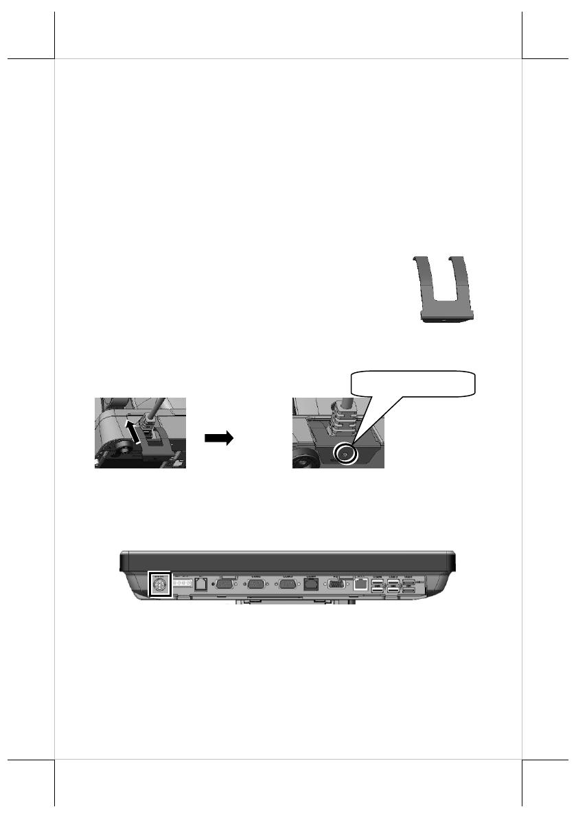
Secure the Power Cord
To avoid the power cord from being pulled out
accidentally, the power adapter kits are shipped
with a power cord bracket.
After installing the power adapter kit and connecting the power
cord to the power adapter, remember to use the power cord
bracket to secure the power cord.
Connecting Power Cable Connector to the Terminal
Before turning turn ON the terminal, connect the power cable
connector to the power jack of the terminal.
CAUTION:
Before connecting the power cable to the power jack of
main unit, do NOT touch any metal pin of the connectors
or circuits to avoid high voltage hazard or electrostatic
discharge damage.
Fixing with screw
16
Powering ON the XT-3815/3915/3915IR
After connecting the power cable to the
power jack of main unit, slightly push to
open the power button cover at the left
side of the main unit.
Then press the power button to power on
the main unit. To power it off, press the
button again.
Once powering off the system, if you want
to power it on again, please wait for at
least 3 seconds.
If the system hangs due to a reason, such as software resource
conflict, please press and hold the power button for 10 seconds
around to forcedly shut down the system.
Power Indicator
There is a power LED indicator serving for
several purposes located at the center of lower
rim of LCD panel. The relationship between the indicator status and
other conditions is summarized below:
Indicator Status
System Status
External
Power
UPS Battery
Powering Up
Off
Off
Off
Not present
Not possible
Off
Off
Off
Present
Not allowed
Green
Off
On
No influence
Allowed
Blue
On
On
No influence
N/A
Blue/Flash
On
Off
Activated
Green/Rapid Flash
On
Off
Battery low
Installing an Operating System
This product is highly professional equipment. Therefore, we do
NOT encourage you to install any operating system into this
machine. Posiflex Technology, Inc. shall not be responsible for any
technical support to questions on this aspect. We suggest that you
contact your dealer for OS installation.
17
Specifications
XT-3815/3915/3915IR
CPU
Intel Bay Trail-D J1900 2.0G up to 2.42G, 2M Cache, 4 core
Memory
DDR3L 1333 FSB, SO-DIMM socket *1, 8G (Max.)
OS
POSReady 7 / Win 7 / Windows Embedded 8.1 Industry / Linux per
request
Display
XT-3815:
15-inch TFT LCD monitor (1024x768) with true-flat pc touch panel
XT-3915:
15-inch TFT LCD monitor (1024x768) with resistive touch panel
XT-3915IR:
15-inch TFT LCD monitor (1024x768) with infrared touch panel
Storage
SATA storage x 2 (one for 2.5” HDD/SSD and the other for 1” SSD
only), or optional eMMC module x 1
Ethernet
10/100/1000 Mb x 1 port
WLAN
Optional, through mini PCI-E interface
Power
Supply
12 VDC power adaptor, 60W / optional UPS battery (2300mAh/12V)
Serial port
RJ-45 X 1, DB9 X 3, RJ-50-to-DB9 cable (Optional)
Parallel port
proprietary port connector in jumper setting window
(by specially optional conversion cable)
CR Port
1 port, available for controlling 2 CR.
USB Port
Standard, 6 ports on the I/O plate (USB 2.0 X 5, USB3.0 X 1), 1 port on
the left side (USB2.0), 3 USB headers reserved for internal USB device
use
PS/2 KB
Port
Pin header on back window
Audio
Built-in 2W audio speaker
Extension
slot
Mini PCI-E slot, with USB signal
Power-Off
Control
Hardware button or by software control
Power
Switch
Soft switch
Power-ON
Wake-Up
Through alarm or LAN
Mechanical
installation
Desktop or wall mount
Power LED
Indicator
Power ON/ standby, bi-color LED indicators
Temp &
Humidity
Operation Temp.: 0 to 40 / Storage Temp.: 20 to 85
Humidity: 10 to 90 %; 5 to 90 % (operation condition)
The product information and specification are subject to change without prior notice.
To get the detailed information on XT-3815/3915/3915IR, please check this model from
Posiflex Global Website
(http://www.posiflex.com/en-global/Download/download).
18
<MEMO>
19
<MEMO>
20
<MEMO>
  • Page 1 1
  • Page 2 2
  • Page 3 3
  • Page 4 4
  • Page 5 5
  • Page 6 6
  • Page 7 7
  • Page 8 8
  • Page 9 9
  • Page 10 10
  • Page 11 11
  • Page 12 12
  • Page 13 13
  • Page 14 14
  • Page 15 15
  • Page 16 16
  • Page 17 17
  • Page 18 18
  • Page 19 19
  • Page 20 20

Posiflex XT-3815/XT-3915/XT-3915IR User manual

Type
User manual
This manual is also suitable for

Posiflex XT-3815/XT-3915/XT-3915IR is a fanless LCD touch terminal with a range of features designed for various applications. It boasts an Intel Bay Trail-D J1900 processor, a 15" TFT LCD monitor with true-flat Projected Capacitive/resistive/Infrared touch panel, and DDR3L SODIMM memory expansions up to 8GB. With its water-resistant structure, foldable base, and optional items like WIFI, connection cables, and integration kits, the XT-3815/XT-3915/XT-3915IR offers flexibility and customization for diverse business needs.

Ask a question and I''ll find the answer in the document

Finding information in a document is now easier with AI