Page is loading ...

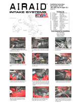
Intake Kit Installation Instructions: 97-02 Jeep Wrangler TJ L4-2.5L Stage 2
Complete Stock Intake.
Disconnect battery before install.
Step 1
Loosen bolt on core support bracket using 13mm socket
or wrench.
Step 6
A)Top view: Secure housing using hex screws, fender
washers , wavy washers and nuts. B)Bottom view:
Tighten using 10mm socket or wrench.
Step 11
Loosen clamp on stock intake using 5/16” nut driver.
Step 2
Remove upper half of air box. Loosen the 3 bolts on bot-
tom of air box using 8mm socket or wrench and remove.
Step 7
Allign grommet from step 8 and position in hole to prevent
core support bracket from vibration.
Step 12
Loosen clamp on throttle body using 5/16” nut driver.
Step 3
Attach grommet provided and install on core support
bracket.
Step 8
Loosen bolts holding in stock intake tube on valve cover
using 8mm socket or wrench and remove.
Step 4
Loosen bolt on core support using 10mm wrench. Save
bolt for later install.
Step 9
Pull crank case line away from stock intake and remove
from vehicle.
Step 5
Attach trim seal to housing and install. Make sure core
support bracket slides through hole on housing.
Step 10
advanced FLOW engineering™
P.O. Box 1719
Corona, CA 92878
Support: 951-493-7100
aFepower.com Complete Kit w/ Parts
Kit P/N: 51/54-11832
Make: Jeep
Model: Year: Engine:
Wrangler 97-02 L4-2.5L
Tools Required:
5/16” nut driver
1/4” nut driver
Flat head screwdriver
8MM socket or wrench
10mm socket or wrench
Ratchet w/extension
Parts List:
1 Air filter ( P
Pro-5R
™ 24-30018 or
Pro Dry S
™ 21-30018)
1 Housing (05-00086)
1 Coupler, elbow (05-00395)
1 Coupler, straight (05-00570)
1 Tube, intake wrinkle black (05-01082)
1 3/4” trim seal @ 25.5 “L (05-00007)
4 Washer, flat fender (03-50074)
2 Nut M6 (03-50059)
2 Washer, wavy M6 (03-50058)
2 Screw, hex M6 (03-50057)
2 Clamp, #044 (03-50019)
2 Clamp, #048 (03-50007)
1 Grommet, rubber (03-50076)
2 Mini clamp, #008 (03-50077)
1 5/8” hose @ 7.5L” (05-00069)
™
Secure core support bracket using 13mm.
Step 13
Secure bracket on housing using screw from step 9 using
10mm wrench.
Step 14
B
Remove crank case line from engine.
Turn page over and continue to page 2
Step 15
A
06-80351 Pg.1

Intake Kit Installation Instructions: 97-02 Jeep Wrangler TJ L4-2.5L Stage 2
Attach elbow coupling with #048 clamps to housing and
position. Do not tighten.
Step 16
Attach straight coupling with #044 clamps provided on
end of intake tube and position to housing and throttle
body.
Step 17
Install 5/8” hose with mini clamps provided and attach to
engine and intake tube. Secure mini clamps using 1/4” nut
driver.
Step 18
Install air filter and tighten all clamps using 5/16” nut
driver. Reconnect battery terminals.
Step 19
Your installation is now complete. Make sure to check all
hoses and tighten any clamps or hardware if necessary.
Thank you for choosing aFepower.
Step 20
advanced FLOW engineering™
P.O. Box 1719
Corona, CA 92878
Support: 951-493-7100
aFepower.com
™
Restore Kits
90-50001 Blue Aerosol
90-50501 Blue Squeeze
90-59999 Pro Dry S™ Cleaner
Pre-filter 28-1008x
12 3 412 3 4
Accessories Available:
Note: Filter Cleaning and Re-oiling: When cleaning your aFe filter, be sure to use only aFe’s “Restore Kit” (aFe P/N: 90-50001 blue oil aerosol, aFe P/N: 90-50501 blue squeeze bottle oil,
aFe P/N: 90-59999 P
Pro Dry S
TM cleaner only.)
Pro Dry S
TM cleaning: see cleaning instruction sheet 06-00074. For replacement part(s) or “Restore Kit” please call aFe sales/tech support @ 951-493-7100 black, and 28-10014 blue
Replacement Air Filter:
Pro-5R
™ 24-30018
Blue Media
Pro Dry S
™ 21-30018
White Media
06-80351 Pg.2
/


