Page is loading ...

www.SteamPoweredRadio.Com
AUG
2
7
2004
FM-25K
Service Information Supplement
This FM-25K Service Information Supplement
is
a technical manual
intended
for
use
by
your
transmitter
maintenance
personnel.
The goals of this manual are to assist you
in
getting the best
performance from your FM-25K transmitter, and to save you time.
We included "how to" information, and other knowledge acquired
through the experience of Harris service personnel.
Also included
is
some
of
the life history of the FM-25K transmitter
and concise information about updates.
This information
is
grouped alphabetically by section, and then
alphabetically by topi
c.
For a topical reference, please refer to the index.
For help
in
the identification of part numbers, please refer to the
applicable drawing.
R:
\service\Radio\Product Support\
Fm
\Fmseries\Fm25k\
Se
rvice Supplement\Fm25serv 4/25/00
pdf 11 Dec
2001
Copyright Harris
Caution!
This transmitter contains lethal voltages. Use safe working
practices, and make use of the protection devices provided
in
the
transmitter.

www.SteamPoweredRadio.Com
Control
Section
AC
Phase Loss Protection
The original means
of
protecting the transmitter from
an
AC
phase loss was accomplished on
contactor assembly K1. Part
of
the contactor assembly was a thermal type cutout, which opened the
circuit if the current to the blower motor was too high.
Better methods
of
protecting against an
AC
phase loss are available now, and the function
of
K1
can
be changed to simply being a contactor.
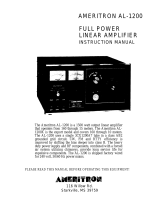
A device called a phase monitor relay can be installed to
monitor the 3
AC
phases. It not only will monitor the presence
of
the 3 phases, but is also sensitive
to phase balance, and phase sequence. Its contacts can be wired to interrupt the blower contactor
circuit if there
is
a detected
AC
phase problem.
We
recommend that the phase monitor relay be installed with its contacts
in
series with the primary
of
the low voltage power supply. With this connection, the transmitter will incur a complete shutdown
if there is a loss
of
phase, thereby protecting all 3 phase circuits.
Parts required to install the Phase Monitor Relay:
Qty
Part Number Description
1
7 40-0495-000 Phase Monitor Relay
1 404-0707-000 Socket
1 402-0142-000 Fuse Block
3
398-0011-000
Fuses
12 354-0634-000 Push-on lugs
12 354-0010-000 Ring lugs
12 354-0005-000 Spade lugs
4 336-1138-000
#6 self tappinq screws
4 310-0012-000
#6 flat washers
Refer to the attached diagram for the recommended connections.
2

www.SteamPoweredRadio.Com
:3
ph
asP
AC'
In
p
11
t.
·-
·;n
cl
~
-
(
~
TB l
FM
•)i--.K
-
/,
,,
,_)
Pha:~
:e Monitor Relay
In:~
:
talla
tion
/~
PhasP
Mo
ni
to
r Relay
Ne
w 3
po
le fuse
bl
oc
k
-
~
\
(
\
I
<
\
,·
\
!
-
j
\
)
\
-
Use
18
gauge
w
ir
e
Nol.e:
Ph
ase
ro
tati
on
m
ay
n
eed
to
be
ch
an
ge
d
in
o
rd
er
fo r
Lh e
un
it
to
lig
ht. t
he
led.
C
ha
nge
t he
ph
a
se
rota
ti
on by
,;
wa
ppin
g
an
y two of
t
he
3
ph
ase
wirPs
to
the
monitor
re
la
y.
3
6
J,
I
ot
con
necte
d
7
J,
No
l.
u
sed
j
Co
nn
el'
! lo wirP
:_\(j
N .
0.
8 ,,__
____
afte
1· it
is
disc·
on
n
ec-ted
j
fl
·om T7-
1.
Com
1 ,
1
~----
To
T7,
term
in
al
1
N.
C'
. 2
'f
Not
w_;ecl
Th e
se
n s
it
ivi
ty
adjust
mt>
nt
,
;l10ul
<I
be
se
l.
abo
ut
5%
below t
he
Lh r Psh old
wh
pr e
th
P
l
ed
on t
he
m o
nitor
r
r>
l
ay
illu
m
in
ates
.

www.SteamPoweredRadio.Com
M<"lal Fol I
F
~A~25
K
Relay
(View
from
Pha:~;e
Mo
nitor
In:~;tallct
ti
on
back
door
,
looking
left)
Rcrnove
Uw
l.llf•nu,tl
ove
rJoacl
sec-t
.ion
and
1.
hP
n·
sel
so)enoid
from
Kl.
f
fr-
wirr as s
hown.
Wire
44,
whif·h
l!,Oes
!
o
TB2-:1
on
the
AC
Conl.rnl
l
e'
r
may
he
n~m
ove<l
co
rnplelel
y.
0 1·
i
nsulai.ed
from
other
s
urfaces.
AC:
Controlln
Phase
Monito
r
Relay
[:]
\
l o
T7
te
,mm,d
J
1(2
C.:
011111.
:1
I
lo
1111e
3H
\ IPIHOH•cl
f1nm
T7-J)
R3
\
Momit
I.he
Phase
Mnnit.or
ffr•
J
ay
IH•rP,
about
13
5/8"
from t.he
fl
oo
r:
and
1
1/4"
from
I.h
i~
had.:
(~dgt
!.
Mount
U1
(~
l'u
~c
bl
ock
ahout
4"
fro111
the
trausmit.t
er
floor,
ahoul
I"
fro1n
t.h
e fold in lit e ch
assis.
Bf'
s
ure
to c
ln·
ss
I.h
e
wiring
awa
y
fro1T1
I.
he
hi
gh volt.agf'
c·o
nn
e
di
on s.
\l
'il'i11g
1.o
TBl
(AC)
(
Wire e
ulrance
hol
e.
Floor
4

www.SteamPoweredRadio.Com
Air Switch (604-0397-000)
With age, pressure type
ai
r switches eventually lose their ability to sense that there
is
air pressure.
Adjustment can usually restore closure, however, the switch will soon open again. Replacement is
then needed.
Unfortunately, protective devices such
as
air switches often get bypassed
in
the interest of getting
back on the air, then subsequently become forgotten.
For this reason it
is
a good idea to keep a spare air switch
on
hand, and periodically check the air
switch operation.
Check the air switch operation with just the Filaments on. Use a piece of cardboard to block off part
of
the air intake. The air switch should remove the
fi
lament
vo
ltage when you have blocked off about
half of the
ai
r intake.
The air switch
is
mounted to the side of cavity nearest the Controller housing. The adjusting screw
is
located
in
the center of one side of the switch. Turning the adjusting screw counterclockwise wi
ll
increase the sensitivity (to make the switch close).
If you prefer a more exact method of checking the air switch adjustment, you can insert a manometer
into the pressurized portion of the cavity. Use any of the screw holes that are just below the cavity
shorting deck.
You can make a crude manometer by forming some clear plastic tubing
in
the shape of a "U". Use
enough tubing so that you have a vertical length of about 6 inches per side of the "U".
Put enough water
in
the tubing
so
that the water level is about half way up.
Insert one end of the tubing into the pressurized area. The degree to which the water
is
displaced
between one side
of
the "U" and the other
is
the measurement of air pressure
in
inches of water.
Example: The water level on one side drops 1 inch,
and
the other side raises 1 inch.
The
air
pressure
is 2 inches.
T
he
normal amount of pressure
is
2.5 inches or more. The desired dropout threshold for the air
switch is 2.0 inches.
Digital Logic Board (992-5433-001 )
With older version Digital Logic boards, some have experienced a random control problem wherein
the HV will not come
up
unless you turn the Filaments off, then start the turn on sequence all over
agai
n.
The problem centers around filament flip flop circuit U3B
on
the Digital Logic board. Transient
energy can cause the flip flop to
go
into the wrong state, and it will not be reset without a Filament
OFF command. Impulses that can cause
th
is can come from an AC line transient, a tube arc, or
ot
he
r similar disturbance.
This problem can be reduced or sometimes eliminated by adding a
.01
uF capacitor from TP5 to
g
ro
u
nd
on the Digital Logic board.
5

www.SteamPoweredRadio.Com
A more effective solution
is
accomplished
in
newer Digital Logic boards by the inclusion of integrated
circuit
US.
The newer type Digital Logic board
is
a direct replacement for any older versions.
Interlock Switches
The interlock switches have two poles, one that
is
in
the coil circuit of the contactors and HV shorting
solenoids, and one that
is
used to operate the led indicator circuit.
Sometimes the interlock switch contacts that are
in
the coil circuit may open, but the contacts that are
in
the indicator circuit may not close. This creates a situation
in
which you have symptoms
of
an
open interlock, but
no
indication to that effect.
In
an FM-25K,
an
open interlock
in
the HV cabinet will
disable the contactors
so
that the screen and plate supplies do not energize.
In
the Main cabinet, an
open interlock will keep the blower motor, bias supply, and HV Power Supply from running.
If you experience these symptoms, test the AC side of the interlock switches for closure. This can be
done with the power off, using
an
ohmmeter. Exercising of the switches may clear the problem, so
be
conscious of this possibility. Otherwise, you may defer the problem to another time by not
knowing which switch was the problem.
Power Cutback
Several customers have had a need for a power level cutback function. Typically the reason for this
is
operation
on
a standby AC power generator that
is
unable to handle the normal full power load of
the transmitter.
There are various ways to do this, each with their own advantages. The best
in
terms of electrical
performance and functionality
is
to switch variacs
in
the screen power supply. This gives you the
ability to easily and independently set the two power levels, and yields the most stable operation for
the low power mode.
At the other end of the spectrum in terms of cost
is
switching another potentiometer
in
the IPA power
control circuit.
In
either case, steps will need to
be
taken to either disable or accommodate the automatic power
control ci
rcu
it.
If you have a need for power cutback, you may contact us to discuss your situation and alternatives.
Remote/Local Switching
Depending on whether the remote local switch breaks before it makes, your transmitter might
sometimes trip off when you switch between one mode and the other.
To solve the problem, add a 1
uF
capacitor, Harris part number 526-0050-000, across R99 on the
Analog board.
VSWR Fold back Kit (994-9006-001)
Automatic VSWR Foldback circuit
is
available to retrofit older transmitters. The VSWR Foldback kit
provides the means of automatically lowering the screen voltage
as
the VSWR gradually becomes
too high, then automatically returns it to the normal level as the VSWR problem clears. This is a very
useful function
in
climates and installations affected by the accumulation of ice on the antenna.
Also please refer to the discussion of the Full Range Screen Control.
6

www.SteamPoweredRadio.Com
General Topics
Circuit Breaker Information
AC line surges at a few sites necessitated changes
in
the trip curve of some
of
the circuit breakers. If
you experience random tripping of the circuit breakers listed below, please check yours to see what
trip curve you have. A change
of
circuit breaker type may
be
all that
is
required.
The present breaker part numbers and types for the Main Cabinet are as follows:
CB1
Filament breaker 606-0806-000
15A, curve 65F
CB2 Bias breaker 606-0827 -000
5A, curve 65F
CB3 IPA breaker 606-0581-000
20A, curve 62
CB4 Blower breaker
606-0581-000
20A, curve 62
For the High Voltage Power Supply, the circuit breakers should be:
CB1
Screen breaker
606-0579-000
1 0A, curve
61
CB2 Blower breaker 606-0552-000
3A, curve 3
Frequency change
Changing frequency involves skills and test equipment not readily available at most stations. Several
parts are often required.
If you have a need to change frequency, we can work up
an
information packet for you. This packet
includes a list
of
components to change, a procedure, and some target values for the power level you
require. There
is
a fee for this service.
Incidental AM/Bandwidth Considerations
The basic requirements for good bandwidth are sufficient
RF
drive to the tube, proper tuning, and
heavy loading
of
the PA. There are other contributing factors, but these are the main ingredients
in
adjustments for good bandwidth as far as the power amplifier
is
concerned.
Proper loading
is
with the power output peaked. Going beyond this will sacrifice efficiency.
The power output should also
be
peaked with the PA Tuning control.
The IPA reflected power should
be
minimized with the Grid Tuning and Input Match controls.
A minimum target value for PA grid current
is
15 to 20 ma.
The FM-25K generally has good bandwidth. The exception to this
is
when the power level
is
significantly reduced, but the Plate Voltage
is
left at the full amount. See the discussion on TPO
changes.
7

www.SteamPoweredRadio.Com
Spurs,
AM
lntermod
In
installations where an
FM
transmitter
is
co-located with
an
AM transmitter, it
is
possible that spurs
will be generated that are a product
of
the AM signal mixing with the FM.
In
our experience, this
is
a
result
of
the AM
RF
getting onto the cable between the stereo generator (or STL) and the exciter.
This
is
most likely to happen
in
a system where a balanced composite source
is
feeding a balanced
input.
In
this case, the shield
of
the coax
is
not really functioning as a shield. It
is
more like a pickup
device for the AM signal.
The solution
is
to install a triaxial cable
in
place
of
the composite coax, and ground the shield
of
the
triax.
We sell triaxial cables with connectors and ground lugs installed. Select the part number you need
based on length:
3ft 922-0014-001
5ft 922-0014-002
1
Oft
922-0014-003
15ft 922-0014-004
25ft 922-0014-005
40ft 922-0014-006
Spurs,
FM
lntermod
When two stations are close geographically and
in
frequency,
RF
intermod spurs can
be
generated.
This
is
a result
of
mixing
in
the PA tube of one station's second harmonic with a signal received from
another. This produces
an
in-band difference signal.
For example, suppose there are two stations
in
close proximity and one station
is
on 100.1 MHz and
the other
is
on 100.9 MHz. The transmitter on 100.1 MHz has a second harmonic within its PA stage
which is 200.2 MHz.
Note: This intermod effect has nothing
to
do
with second harmonic output
of
the transmitter.
In
other
words, the problem does not depend
on
adjustment
of
the output filtering.
In
the PA, 200.2 MHz will mix with 100.9 MHz from the other station to produce a difference signal
of
99.3 MHz.
To solve the problem, a cavity type filter
is
needed
in
the output coax to filter out the other signal.
The amount
of
filtering needed depends
on
frequency separation, and the level of the offending
signal. Contact our Sales department for further information.
Spurs, In-Band
Aside from the possibility
of
RF
intermod products, a transmitter can generate spurs on its own if
there is an instability problem
in
one of its amplifier circuits.
In
such cases, it becomes necessary to
isolate the problem to the offending stage.
One method of isolating instability
in
a particular stage
is
to rock the tuning controls back and forth
through their normal setting to see if the spurious problem
is
affected. This will generally give you a
"feel" for where the problem lies.
8

www.SteamPoweredRadio.Com
If the problem
is
unaffected by basic tuning adjustments, the problem may
be
the exciter.
In
a
number
of
instances we have found that spurs at about 200 kHz or 400 kHz intervals are generated
by the MS and MX-15 exciters. The cause has often been the electrolytic capacitors
in
the
RF
Amp
drying out.
The life expectancy
of
electrolytic capacitors
is
about 10 years, so C8 and C18
in
the RF Amp should
be
replaced if this problem
is
suspected. They are 20 uF,
50
volt axial lead capacitors. The Harris
part
number
is
522-0256-000.
TPO (Transmitter Power Output)Changes
The type accepted power output range for the FM-25K
is
7350 watts to 25730 watts. Within this
range, there are various criteria for best operation. For power levels below
10
kW, it
is
best to set the
HV Power Supply transformer
in
a wye configuration. This will reduce the Plate Voltage to about
5300 volts, which will
be
a major step
in
reducing the power and maintaining good performance.
See the attached drawing
of
the Wye and Delta configurations. To connect the HV transformer
primary
in
a wye, you would first need to disconnect all the primary connections, then join the +10
terminals together. The AC wires from the contactor would then connect to the 240 volt terminals.
This would give you the lowest
vo
ltage output. Tapping the transformer to the lower numbered
terminals (208, 0 for example) will give you somewhat higher plate voltage.
For power levels above 10 kW, you will probably have to leave the HV transformer
in
the delta
connection. However, you should connect the primary wires to the highest numbered terminals to
give you the lowest usable plate voltage. Reducing the plate voltage
is
your best initial step
in
changing to a lower TPO because it helps accomplish the goal without any sacrifice.
Other handles for power reduction are screen voltage, bias, and IPA power.
9

www.SteamPoweredRadio.Com
(
•y<
\
-
.,
Delta ('.onnectio11
240
OJ' 2flf\
t.e
rmino.1
'i
)
'
j
I
,)
_1
I
-10,
0, OJ' +10
term
i11a
l
C
r
'j
-
JO,
0,
OJ'
+/ 0
_)
l.
e r1ni11nl
(
7
:!.
10
or 2
0H
- - -
-~-~
' y y y y y y y y y l___i
240
01·
;.'()/j
- JO,
0,
(Ir
+
JO
lenninal
tenniua]
WY
E
Connection
240
or
208
I
Le
rrn
i1wl
-
-
---
I))-
r-(\
\
!)
(\
\
)
)),)
)
({("
\
I ) \ - 10, 0,
()J'
+ J
()
L lel'
minals
)
)
)
~
~
)
)
2,
10
or 20fl
term
inal
2.
10
0
1"
208
l
1•
1·rnin,,l
.foining
the
+ 10 tt.,nni
nal
s
together,
and
applying
the
AC
to
the
i
208/240
voli
lenninals
fonns
n wye c
ir
c:uil.
For
a
given
lin
e volt.age
and
tap
sel Ung,
th
is
reduces
l.h
e o
utput
volt.age by
Lh
e
square
root
of
~L
Using
th
e
higher
nu1nh
er
ed
taps
results
in
lowp,r
output..
Using lower
uu1nb
erecl
prirnary
tap
sett
in
gs r
e~rn
l
t.s
in
high
er
voltage
nut.put.
HV
Power Supply
Dash pots (magnetic overload relays)
A small bottle
of
lightweight oil is supplied with the magnetic overload relays,
or
dash pots, as they
are often called. The magnetic overload relays are
K1
and K2 at the AC entrance
in
the High Voltage
Power Supply.
The purpose
of
the oil
is
to slow the response
of
the magnetic overload relays. This
is
usually not
needed for an
FM
transmitter because the AC line current is relatively steady. However,
in
rare
cases where the magnetic overload relays trip randomly, you should first check the trip settings. If
you need to add oil, use just enough to cover the bottom
of
the cup
on
the magnetic overload relay
assemblies.
10

www.SteamPoweredRadio.Com
To remove the cup, release the spring tension by moving the spring off the cup. The cup assembly
should then come out
in
your hand.
The plunger that extends from the cup assembly has grooves
in
it that correspond to the current trip
markings on the stationary piece still
in
the transmitter. The plunger adjusts vertically by turning it the
appropriate direction. The normal setting is the second line up, which corresponds to 162 amps.
HV
Rectifier Emergency Connection
Sometimes you will have one bad rectifier and no replacement on hand.
In
this instance, it is often
possible to use the half-tap setting of the High Voltage Supply to your advantage.
In
the half-tap position (using the High/Low knife switch), the power supply only uses half
of
the
rectifiers. The trick
is
then to utilize the good halves of your rectifiers
in
those positions that are
in
circuit
in
the half tap position. Be sure to disconnect the shorted rectifier sections because they will
otherwise still be
in
circuit.
HV Rectifier Testing (384-0650-000)
Usually when a HV rectifier fails, it goes to a shorted mode that
is
easy to identify with an ohmmeter.
Good rectifiers usually measure open on an ohmmeter, so there may
be
times that you would like a
little assurance that the rectifiers are good; not just open.
You can do this with
an
ordinary 120-volt light bulb, and some connections to 120 volts AC. Take the
rectifier out
of
circuit, and wire it
in
series with a 120 volt, 40-watt light bulb, then connect that
combination to a 120 volt AC source.
If the rectifier
is
shorted, the light bulb will
be
at full brilliance.
If the rectifier is open, the bulb will not light at all.
A good rectifier will result
in
the bulb being half-lit.
HV Shorting Solenoids (590-0037-000)
Fa
ilure
of
the HV shorting solenoids will overload the Bias circuit breaker, and cause it to trip.
AC brown out conditions can stress the solenoids, thus contributing to their failure. The reliability
of
the solenoids can be improved by providing the solenoids with a stiffer and somewhat higher voltage
power source.
Service Bulletin FM-364 covers this modification
in
greater detail.
11

www.SteamPoweredRadio.Com
HV Supply Secondary Wiring
We have observed
in
several transmitters that the brown HV wire that goes between the transformer
and rectifiers can develop a whitish discoloration where the wires are bundled or run along the
chassis. This whitish discoloration
is
an
effect of corona.
When replacing the wiring,
it
is
best to route it directly from the transformer to rectifiers without
bundling them or routing them along the chassis. Bulletin FM-399 covers this
in
further detail.
IPA Section
Note: The following information applies mostly
to
the original 5 module IPA system. See the
information on the Outboard IPA for information on an IPA upgrade.
8 Port Combiner (992-5440-001)
The 8 Port Combiner has given very few problems, but one that has been encountered can occur as
a result
of
one or more of the coaxes being stretched too tight to reach its designated connector.
In
some cases, this has resulted
in
one of the 8 Port Combiner coaxes being pulled loose from the
circuit board.
If a problem is suspected, examine the solder connections for the 8 BNC jacks on the Combiner.
Re-solder
as
needed, with the coaxes disconnected.
Since the 8 Port Combiner
is
symmetrical,
it
does not actually matter which coax
is
on
what
connector. They may
be
connected
in
any order which suits the reach of the coaxes.
C4
Grounding
The IPA power supply filter capacitor
C4
will
be
able to filter transient energy more effectively if it has
a fairly direct ground.
In
some units, C4 obtained its ground (-) connection through a cable to the IPA mainframe. The
transient filtering can be helped by adding a copper strap or heavy wire from the minus (-) side of
C4
to the mounting hardware for C4. If you install a wire, use 14 gauge or larger.
Coax Cable Aging
With heat and time, we find that the RG-213 coaxial cables used for the IPA output circuit get stiff
and eventually brittle. This loss
in
flexibility can lead to a loss
in
connection reliability.
Check the condition of your cables periodically.
The part number for the coax from the 8 Port Combiner to the IPA Lowpass Filter
is
929-7815-001.
The part number for the coax from the IPA Lowpass Filter to the PA input
is
929-7814-001 .
Exciter Output Setting
The optimum drive level from the exciter
is
determined partly by the difference between IPA
Unregulated Voltage (Vunreg) and the Regulated Voltage (Vreg). Frequency
is
also a factor.
12

www.SteamPoweredRadio.Com
In
general, the gain of the
RF
Driver and IPA
is
the highest at the low end of the band. Therefore,
the exciter output requirements are least at the low end
of
the band, and highest at the high end
of
the band. Having the exciter output too low can cause
RF
stability problems, and inability to produce
enough IPA power.
Too high
of
output from the exciter can over drive the
RF
Driver module, and damage components on
its input circuit. Having too much exciter output can also cause you to set the regulated voltage (IPA
Power control) lower than it should be, thus resulting
in
excessive power dissipation
in
the IPA
regulator transistors.
One method
of
setting the exciter output
is
to first set the Regulated Voltage to the ideal range (23 to
27 volts). Do this with the exciter level lower than normal.
Then, raise the exciter output until you have the required IPA power. Minor adjustments
in
IPA power
should subsequently
be
made with the IPA power control.
IPA LPF/DC (992-5620-001)
If you suspect a problem with the IPA Lowpass Filter/Directional Coupler unit, the best and simplest
approach
is
to give it a good visual inspection. Detach it from the wall
of
the transmitter cabinet, then
inspect it under good light.
In
particular, look at the variable capacitors,
C1
and C3. Their glass should
be
clear. If you find one
of
them has glass that has turned foggy, chances are
it
has failed. Also inspect for any other
components that may have over heated.
The IPA LPF/DC
is
a 50 ohm device
on
its input and output. Therefore, the input can be checked to
see if its impedance
is
50 ohms at the carrier frequency with the output terminated into a known good
50 ohm load.
We
do this with a tracking generator, calibrated directional coupler, and spectrum
analyzer. It can also
be
checked with
an
in-line wattmeter, but with lesser precision.
Various improvements have been made
in
the IPA LPF/DC. Most
of
these came about from using it
in
higher power transmitters.
Improvements were made to handle higher IPA power levels. Another change was made to reduce
its reflected metering sensitivity to harmonic energy. This results
in
better capability to null the IPA
reflected power reading, even
in
the presence of harmonics
in
the drive signal.
IPA Mainframe
In
cases where there are recurring IPA module failures, the problem might not
be
the modules. The
problem might be
in
the Mainframe.
Solder joints can fail after several years. Components such as resistors may also change
in
value.
These can affect the load impedance to the modules, and affect the
ba
lance
of
loading
on
the
modules.
When there
is
some question about the integrity
of
the inner workings of the IPA Mainframe,
it
may
be
advisable to remove the IPA Mainframe for inspection of the Motherboard and Splitter/Combiner
Board. When the solder connections look dull,
it
is
best to remove the old solder, and apply new
solder.
13

www.SteamPoweredRadio.Com
IPA
Mainframe
Removal
Disconnect the cabling from the underside
of
the IPA unit. This would include the RF input coax
which comes from the exciter, and the DC power cables coming from the IPA power supply.
Separate the white in-line connector in the cabling from the IPA power control pot to the IPA housing.
This cable consists
of
3 white wires.
Disconnect the eight brown coaxes that connect to the
8 Port Combiner. Position the connectors
where
they
will not grab as you later pull the IPA assembly forward.
Remove the top module from the IPA section. This will provide a place for a hand when you are
ready to remove the IPA section.
Remove the screws from the left and right edges
of
the front panel which contains the IPA section
and the
PA
tuning controls.
At
this point, the whole front panel should come forward. Note: The
PA
tuning controls will uncouple; there is no need to remove any set screws.
Putting the IPA section back
in
place will require
an
assistant to get the pin-coupled shafts lined up.
IPA Multimetering Kit (994-8491-001)
Early version transmitters did not include a multimeter for the IPA other than the
IPA
forward and
reflected metering. The IPA multimeter kit adds metering for Unregulated Voltage, Regulated
Voltage, IPA 1, IPA
2,
IPA
3,
IPA
4,
and Driver. This can be especially useful to find out if the
module current readings are balanced.
I
PA
Oscillations
Symptoms
of
instability
of
the IPA section will show up in the IPA reflected power reading. You will
find that the reflected power reading will move in abrupt steps as you tune the
PA
input controls.
If you observe such actions, you may need to add a feedback circuit on the IPA modules. This
is
a
resistor-capacitor series combinati
on
from the base to the collector
of
the RF transistors. See service
bulletin FM-218
for
further details.
If your modules already have this modification, there may be a matching problem between the RF
Driver and the IPA modules.
In
this case, adjustment
of
the coax length between the 2 Port
Combiner and 8 Port Splitter may be needed. Depending on your circumstances, it
may
be
advisable to inspect the Splitter board before making any adjustment. The most likely time to require
any
adjustment is when doing a frequency change.
IPA Supply Voltage
For the typical
300
to 350
watts operation, the required IPA Supply voltage needs to be
30
to 32
volts. This is measured at the Vunreg test jack on the lower front
of
the transmitter.
The optimum voltage difference between the unregulated and regulated voltage
is
5
to
8
volts. For
typical operation, this means that the optimum regulated voltage
is
in
the range
of
22 to 27 volts.
If the voltage drop across the regulator is too low, there will be
an
AM noise problem because the
regulator is unable to take out the power supply ripple.
If the voltage drop is too high, the regulator pass transistors will be stressed by excessive dissipation.
14

www.SteamPoweredRadio.Com
For situations when you are using much less IPA power, the IPA Supply Voltage could
be
possibly
be
reduced by changing to a higher tap setting on the primary. This,
of
course, depends
of
what your
AC line voltage is. If your AC line voltage
is
high (240 to 250), your transformer
is
probably tapped all
the way up already. Lowering the IPA Supply Voltage may improve the reliability
of
the IPA by
reducing the stress on the IPA Regulator pass transistors.
IPA Transistor Types
The
RF
transistor type available for use
in
the IPA modules
is
the Thomson SD1019-13, Harris part
number 380-0589-000.
Other types used in the past that are now generally unavailable are the Motorola SRF3344, and the
CD2315.
Transistor types generally mix okay, however, you should compare the current draw of the various
modules to see if there
is
a load sharing problem. Gain variations can
be
a problem, even from one
batch to another
of
the same transistor type.
Outboard IPA (992-8466-001/002)
New developments
in
solid state amplifier technology have enabled
us
to now offer a single stage
power amplifier assembly for use as
an
upgrade for the present IPA assembly
in
the FM-25K
transmitter. This upgrade greatly simplifies the IPA section, and should yield more rugged
performance. Installation instructions are contained
in
Service Bulletin FM-400-SLA that is included
with the upgrade parts kit.
The assembly
is
a self contained, rack mountable broad band
RF
amplifier with its own power supply,
cooling and protective circuitry. A conservative 350 watts of power
is
available with no more than 15
watts input. Power output
is
controlled by drive from the exciter. The amplifier
is
internally protected
against overdrive, over current and VSWR conditions. The only connections necessary are
RF
input,
RF
output, and a 197-250 single-phase AC input. A front panel led indicates a fault condition should
the units internal control circuitry inhibit the
RF
output. External front panel test jacks make available
samples
of
the units voltage and current. A front panel circuit breaker provides for on/off power
switching.
All necessary items to implement the modification are included
in
a kit. The Harris part number for
the domestic 60hz kit
is#
992-8466-001 . The Harris part number for a 50hz kit
is
# 992-8466-002.
The IPA upgrade
is
warranted against component failures for a period
of
6 months from date
of
shipment.
Installation
of
the unit requires it
be
rack mounted near the transmitter. It requires 7 inches
of
vertical
rack space. The unit
is
23 inches deep. The weight of the unit (100
lb
.) necessitates that it
be
housed
in
a mounting frame and supported from the rear. The unit has been tested with cable
lengths up to 25 feet. If your installation requires longer cables contact our field service department
for advice. At frequencies above 104 MHz we recommend that the exciter also
be
mounted
in
the
rack with the IPA so that cable length from exciter output to IPA input can
be
as short as possible.
When the installation
is
complete the present IPA modules will normally
be
left
in
the transmitter as
they provide back pressure to the air system which
is
necessary for proper air flow and cooling to the
PA cavity. The old IPA assembly still being intact allows it to
be
available as a standby.
15

www.SteamPoweredRadio.Com
PA
Section
Cathode Inductor
LS
The cathode inductance,
LS,
is
varied according to frequency
in
order to achieve optimum efficiency.
LS
is
a copper strap
on
the underside pf the socket, from the outer filament ring to the base plate
of
the socket (ground). This strap
is
varied
in
length, width, and shape to form the correct amount of
inductance
to
achieve
optimum
efficiency.
Although it may look like only a copper strap,
LS
is
a highly critical adjustment. Because
of
this, it
is
not often possible to obtain the correct adjustment without some experimentation.
The transmitter will function with almost any size
of
strap
in
circuit, but will achieve full output power
and efficiency only when
LS
is
in
proper adjustment.
The
LS
strap can
be
removed from the underside of the socket by leaving the PA tube
in
the socket
while removing the screws that hold
LS
in
place. The purpose of leaving the tube
in
the socket
is
to
hold four posts
in
position
on
the top side of the socket.
When re-installing
LS
,
be
sure to tighten the
LS
hardware as tight as you can get it because any loss
of
contact will affect the result, and cause
LS
to over heat.
It
is
fairly unlikely that you will have to do any adjustment
of
LS
unless you are changing frequency.
Cavity Cover Fasteners (448-0896-000)
All four walls
of
the cavity, including the PA Access Cover, carry
RF
current. For this reason and
others, it
is
important to always fasten all
of
the thumbscrews on the access cover. Securely finger
tightening them might
be
good enough, however, finishing the tightening with a screwdriver
is
best.
Later model transmitters include fingerstock between the PA access cover and the back wall
of
the
cavity, plus more fasteners have been added. The new cover part number is 922-0446-013.
The back wall that accommodates the new access cover
is
943-4 754-026.
Filament
RFI
With more equipment types being co-located, the importance
of
minimizing cabinet radiation has
increased. Meeting FCC specifications for cabinet radiation
is
not always enough.
One
of
the areas that require good shielding
is
the filament circuit. The filament circuit
is
RF
hot
because it also happens to
be
the cathode (as
is
the case of all directly heated cathodes). For this
reason,
it
is
important to shield and de-couple the filament leads.
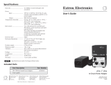
A rectangular enclosure was added below the cavity to accomplish more effective shielding. See
drawing.
16

www.SteamPoweredRadio.Com
If
you
determine
your
transmitter
needs
the
additional
shielding,
you
will
need
the
following materials:
Qty Part Number
Description
30
302-0106-000
Screw, 6-32 X 3/8
16
304-0013-000 ½-13 nuts
30
310-0012-000 #6 flat washer
16
312-0055-000
½" split washers
30
314-0005-000
#6
split washer
24
350-0037-000 Pop rivets, 0.125 X 0.265
6
356-0227-000
Cable ties, high temp.
1
358-04 73-000 Hose clamp 2.25" max
1
358-0935-000
Hose clamp 1.25" max
3
414-0279-000 Ferrite beads
3
516-0235-000
Feedthru caps, 1000
pf
8
822-0506-002
Blocker plates
4
822-0507-002 Teflon washers
4
829-8597-001 Studs, ½-13 X 3.25
4
829-97 45-009 Kapton sheets
1
917-0558-001 Reducer
1
917-0570-001
Filament metering board
2
922-0533-002 Filament leads, top
2
922-0533-005
Filament cables, bottom
1
922-1298-002 Elbow
2
939-0533-006
Filament leads, middle
1
939-8208-001 Enclosure
2
939-8208-002 Divider shelves
1
939-8208-003 Cover
1
939-8208-004
Air feedthru tubinq
1
939-8208-019
Maqnetic shield
17

www.SteamPoweredRadio.Com
Hose
clamp
358-0935-000
Reducer
917-0558-001
Enclosure
939-8208-001
Elbow
922-1298-002
Filament
leads
922-0533-002
(2)
and
cable
ties
356-0227-000
(6)
Six
cable
ties
are
needed
altogether,
two
in
each
part
of
the
enclosure,
and
two
below
the
enclosure.
Filament
leads
939-0533-006
(2)
Studs
829-8597-001
(4)
-
Filament
Enclosure
Use
cover,
939-8208-003,
not
shown
Fasten
cover
in
place
with
302-0106-000
(26)
314-0005-000
(26)
310-0012-000
(26)
,,
,,
0
--
,.;;;,.
·
---
~ "
, ~ " ,
,,
,,
I
.._
I
I
'
'
I
I
(_>
I
I
I
1- -
1
I
I
I
I
0
Filament
metering
board,
not
shown
917-0570-001
Ferrite
beads
414-0279-000
(3)
Feedthru
capacitors
(3)
516-0235-000
-
Hose
clamp,
358-0473-000
Air
feedthru
939-8208-004
Fasten
in
place
with
302-0106-000
(4)
314-0005-000
(4)
310-0012-000
(4)
Magnetic
shield
939-8208-019
should
be
fastened
to
the
filament
enclosure
wall
closest
to
the
front
side
of
the
transmitter.
Dividers
(2)
939-8208-002
Rivets
for
fastening
the
dividers
and
shield
in
place:
350-0037-000
(24)
Cables
to
filament
transformer
922-0533-005
(2)
-
Lug
"'----
Blocker
plates
822-0506-002
(8)
and
Kapton
sheets
829-9745-009
(4)
Neutralization Eccosorb Tile (917-2428-002)
18

www.SteamPoweredRadio.Com
The purpose
of
the square black block on the neutralization flag assembly
is
to absorb RF energy in
a certain frequency range. It was included in the design when some 360 MHz feedback was
discovered
in
the neutralization circuit. All transmitters should have the Eccosorb tile.
Output Plumbing Configurations
In
some installations it has been desirable to locate the Output Lowpass Filter
in
a position that
differs from the recommended setup. This presents some risk
in
terms of harmonic attenuation, and
harmonics effects on the output directional coupler.
For these reasons, it
is
advisable to measure the harmonic output
of
the transmitter while it is
operating into a
dummy
load to be sure it
is
within FCC specifications. If the harmonic output is out
of
tolerance, some adjustment
in
line length ahead
of
the filter may be required.
Note: Harmonic readings taken
by
sampling the signal going up
to
the antenna can be
misleading. This
is
because the impedance
is
not
a
flat
50 ohms,
but rather can be very
different
at
the harmonic frequencies. This difference
in
impedance affects the dB
relationship.
For the effects on the directional coupler, it would be best to re-locate it so that it is on the output side
of
the Output Lowpass Filter.
Output Pre-filter (939-7451-001)
In
transmitters made after July 1986, a filter section was put
in
place
of
the regular center conductor
in
the Vertical section of 3 1/8 inch coax on the output
of
the cavity. This
is
a smaller diameter pipe
with two larger brass cylinders
on
it.
This forms a
pi
circuit consisting
of
two capacitors and a series
inductor.
The purpose
of
this change was to add harmonic attenuation for some harmonic frequencies. This
was especially beneficial when the output directional coupler was installed ahead
of
the output
lowpass filter. With the lowpass filter
in
this position, we found that the length
of
line ahead
of
the
filter was especially critical with respect to the
VSWR
and Forward power readings. Adding the pre-
filter reduced this sensitivity somewhat, however, the coaxial line length can still affect harmonic
output.
Installing the pre-filter, or determining if your transmitter has one, will require that you disassemble
the plumbing at the output
of
the cavity.
PA
Cavity
Pa
rts List
19

www.SteamPoweredRadio.Com
Following
is
a
list
of
cavity
parts,
not
all
of
which
are
included
in
the
regular
instruction
manual.
This
list can
be
used
in
combination with the cavity drawings provided with this information packet. Most
of
the common usage items
in
the following list are
in
bold type.
Qty Part Number Description
1 9925567001 Socket
& Input Ckt Assy (Entire Deck)
1 9294129001 Plate Blocker (Chimney)
1
9294923001
PA
Tube
Access
Cover
With
Fingerstock*
2
3581036000 Clamp, Hose For Top Of Plate Blocker
1 9293989001 Shorting Ring At Top Of Plate Blocker
1 9294322001 Conductor Assv
1 9169985001
Support Assv
1
8293899001 Inductor
1
8294253001 Extension (Grid Tuning, 1/2" Aluminum Rod)
1
9297916001
Flexible Coupling
1 8170685001 Strap
1 9395926001
Plate Bottom Weld
1 8394165001
Plate Short
1
9294927001 Side Assy Cavity
1 9294931001
Side Assy Cavity
1 9434754026 Rear Wall Of Cavity (Compatible With 9220446013)
1
9294934001 Front Wall
1
9170432001 Anode Connector
1 4100153000
Insulator Bshg NS5W-4104
1
4100157000
Insulator Bshq NS5W-4204
2 3350041000
Washer Nylon .75
Id
6
3350010000 Washer Nylon .195
Id
2 4100152000
Insulator Bshq NS5W-4103
1 8135611123 Stud
2
4100156000 Insulator Bshg NS5W-4203
4 3350080000 Washer Nylon
.5
Hole
2 8135611038 Stud, 2-7/16
Lg.
1 3581944000 Coupling 1/4 Bore (Black, With Brass Center)
2
9170559001 Bearing Block Assy
1 6200498000 Adapter 3-1/8 301-014
1 8297490001 Plate Side
1 8297574001 Plate Side
1 9297493001
Plate Tuning Rod
1 9297496001 Plate Tuning Paddle With Fingerstock
1 9297576001
Bearinq Plate Assy
1 9297576002
Plate Assy Bearinq
2 3581165000 Collar 1 /4 Hole
1 9298140001
Pulley Assy
1 9298139001
Pulley Assy
1
4240491000 Plate Tuning Belt (See Gear Drive Upgrade)
4 8135010033 Std off 8-32x1-3/4 1 /2
Rd
4 8170084001 Spacer Bushing Plate
1
9297885001
Cable Assv
20
/