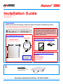
Harris Aurora 5800 is a spread spectrum digital microwave radio that provides reliable and secure wireless connectivity for various applications. With its advanced features, it offers exceptional performance and versatility in challenging environments.
The Aurora 5800 supports both T1 and E1 data interfaces, making it compatible with a wide range of communication systems. It operates in the license-free 5.8 GHz frequency band, allowing for flexible and cost-effective deployment.
This radio features robust weatherproofing, ensuring uninterrupted operation in harsh outdoor conditions. Its compact design and rack-mounting capability enable easy integration into existing infrastructure.


-
 1
1
-
 2
2


Harris Aurora 5800 is a spread spectrum digital microwave radio that provides reliable and secure wireless connectivity for various applications. With its advanced features, it offers exceptional performance and versatility in challenging environments.
The Aurora 5800 supports both T1 and E1 data interfaces, making it compatible with a wide range of communication systems. It operates in the license-free 5.8 GHz frequency band, allowing for flexible and cost-effective deployment.
This radio features robust weatherproofing, ensuring uninterrupted operation in harsh outdoor conditions. Its compact design and rack-mounting capability enable easy integration into existing infrastructure.
Ask a question and I''ll find the answer in the document
Finding information in a document is now easier with AI
Related papers
-
Harris CONSTELLATION Installation & Maintenance
-
-
Harris ZX3750 Technical Manual
-
-
Broadcast Devices HARHDE200-PROFAN Installation guide
-
-
-
-
-
Other documents
-
 Harris Stratex Eclipse 4.6 User manual
-
ADTRAN 2 x E1 User manual
-
Alcatel-Lucent 9500 MXC User manual
-
-
 DTS L54 Series User manual
-
 Plessey MDR2400 User manual
-
-
-
-


