Page is loading ...

Cover photo may show optional equipment not supplied
with standard unit.
© Copyright 2003 Printed
Read the Operator’s manual entirely. When
you see this symbol, the subsequent
instructions and warningsare serious - follow
without exception. Your life and the lives of
others depend on it!
!
356-005M
03/11/03
Z52
®
, Z60
®
& Z72
®
Zero Turning Radius Mowers
Accu-Z
19097
Operator’s Manual
®

Table of Contents
Z52®, Z60® & Z72® Zero Turning Radius Mowers Accu-Z 356-005M
03/11/03
Land Pride
Table of Contents
© Copyright 2003 All rights Reserved
LandPrideprovidesthispublication“asis”withoutwarrantyofanykind, either expressedor implied. While every precaution has been takenin the preparationofthismanual,
Land Pride assumes no responsibility for errors or omissions.Neither is any liability assumed for damages resulting from the use of the information contained herein. Land
Pride reserves the right to revise and improve its products as it sees fit. This publication describes the state of this product at the time of its publication, and may not reflect
the product in the future. The illustrations in this manual are not intended for safe and proper assembly or disassembly of equipment. The illustrations are intended for
ordering parts only.
Land Pride and Accu-Z Razor are registered trademarks.
All other brands and product names are trademarks or registered trademarks of their respective holders.
Printed in the United States of America.
Important Safety Information . . . . . . . . . . . . . . . . . . .1
Introduction. . . . . . . . . . . . . . . . . . . . . . . . . . . . . . . . . .6
Application . . . . . . . . . . . . . . . . . . . . . . . . . . . . . . . .6
Using This Manual . . . . . . . . . . . . . . . . . . . . . . . . . .6
Terminology. . . . . . . . . . . . . . . . . . . . . . . . . . . . .6
Definitions . . . . . . . . . . . . . . . . . . . . . . . . . . . . . .6
Owner Assistance . . . . . . . . . . . . . . . . . . . . . . . . . .6
Serial Number Plate. . . . . . . . . . . . . . . . . . . . . . . . .6
Further Assistance. . . . . . . . . . . . . . . . . . . . . . . . . .6
Section 1 Assembly and Set-Up . . . . . . . . . . . . . . . . .7
Control Lever and Seat Assembly . . . . . . . . . . . . . .7
Remote Air Cleaner Assembly. . . . . . . . . . . . . . . . .7
Optional Equipment Assemblies . . . . . . . . . . . . . . .8
Remote Air Cleaner Assembly . . . . . . . . . . . . . .8
Control Lever Extensions . . . . . . . . . . . . . . . . . .8
Accu-Vac Assembly. . . . . . . . . . . . . . . . . . . . . . .9
Mower Deck Preparation. . . . . . . . . . . . . . . . . . .9
Blower, Pulley and Pulley Cover Assembly. . . .10
Bagger Assembly . . . . . . . . . . . . . . . . . . . . . . .11
Front Lift and Weight Assembly. . . . . . . . . . . . .12
Section 2 Operation . . . . . . . . . . . . . . . . . . . . . . . . . .13
Controls . . . . . . . . . . . . . . . . . . . . . . . . . . . . . . . . .13
Ignition Switch. . . . . . . . . . . . . . . . . . . . . . . . . .13
Throttle Control . . . . . . . . . . . . . . . . . . . . . . . . .13
Choke Control. . . . . . . . . . . . . . . . . . . . . . . . . .13
Control Levers. . . . . . . . . . . . . . . . . . . . . . . . . .13
Parking Brake. . . . . . . . . . . . . . . . . . . . . . . .14
Deck Clutch Switch. . . . . . . . . . . . . . . . . . . . . .14
Deck Lift Pedal . . . . . . . . . . . . . . . . . . . . . . . . .14
Instrumentation . . . . . . . . . . . . . . . . . . . . . . . . . . .15
Electronic Hour Meter . . . . . . . . . . . . . . . . . . . .15
Oil Pressure Light . . . . . . . . . . . . . . . . . . . . . . .15
Safety Start Interlock System. . . . . . . . . . . . . . . . .15
Engine Starting . . . . . . . . . . . . . . . . . . . . . . . . . . .15
Moving Mower with Stalled Engine . . . . . . . . . . . .16
Driving the Mower . . . . . . . . . . . . . . . . . . . . . . . . .17
Steering. . . . . . . . . . . . . . . . . . . . . . . . . . . . . . .17
To Stop or Decrease Speed . . . . . . . . . . . . . . .17
To Increase Speed . . . . . . . . . . . . . . . . . . . . . .17
Operating Suggestions. . . . . . . . . . . . . . . . . . . . . .17
Mower Deck Operation . . . . . . . . . . . . . . . . . . . . .18
Operating Instructions . . . . . . . . . . . . . . . . . . . . . .19
Section 3 Adjustments. . . . . . . . . . . . . . . . . . . . . . . .20
Torque Values . . . . . . . . . . . . . . . . . . . . . . . . . . . .20
Steering Linkage . . . . . . . . . . . . . . . . . . . . . . . . . .20
Control Lever Neutral Adjustment. . . . . . . . . . .21
Control Lever Stops . . . . . . . . . . . . . . . . . . . . . . . 22
Reverse Spring Adjustment . . . . . . . . . . . . . . . . . 22
Steering Dampener. . . . . . . . . . . . . . . . . . . . . . . . 23
Control Lever Adjustment . . . . . . . . . . . . . . . . . . . 23
Park Brake Adjustment . . . . . . . . . . . . . . . . . . . . . 23
Hydraulic Pump Belt Adjustment . . . . . . . . . . . . . 25
Deck Drive Belt Adjustment . . . . . . . . . . . . . . . . . 25
Engine RPM Setting . . . . . . . . . . . . . . . . . . . . . . . 25
Deck Leveling and Height Adjustment . . . . . . . . . 25
Deck Level Adjustment. . . . . . . . . . . . . . . . . . . 26
Deck Cutting Height Adjustment. . . . . . . . . . . . . . 28
Anti-Scalp Rollers . . . . . . . . . . . . . . . . . . . . . . . . . 29
Section 4 Maintenance and Lubrication . . . . . . . . . 30
Maintenance Locations. . . . . . . . . . . . . . . . . . . . . 30
Maintenance Schedule . . . . . . . . . . . . . . . . . . . . . 31
Maintenance . . . . . . . . . . . . . . . . . . . . . . . . . . . . . 32
Torque Values . . . . . . . . . . . . . . . . . . . . . . . . . . . . 32
Tires . . . . . . . . . . . . . . . . . . . . . . . . . . . . . . . . . . . 32
Hour Meter . . . . . . . . . . . . . . . . . . . . . . . . . . . . . . 33
Lubrication . . . . . . . . . . . . . . . . . . . . . . . . . . . . . . 33
Electrical System . . . . . . . . . . . . . . . . . . . . . . . . . 33
Access to Engine and Hydraulic Pumps. . . . . . . . 34
Hydraulic System . . . . . . . . . . . . . . . . . . . . . . . . . 34
Fuel System . . . . . . . . . . . . . . . . . . . . . . . . . . . . . 35
Engine Oil and Filter . . . . . . . . . . . . . . . . . . . . . . . 35
Engine Air Filter . . . . . . . . . . . . . . . . . . . . . . . . . . 36
Over Service . . . . . . . . . . . . . . . . . . . . . . . . . . 36
ImproperInstallation . . . . . . . . . . . . . . . . . . . . . 36
Damaged Filter, Seals or Canister. . . . . . . . . . 37
Incorrect Air Filter Element. . . . . . . . . . . . . . . . 37
Engine Air Filter Service Procedure . . . . . . . . . . . 37
General Engine Maintenance . . . . . . . . . . . . . . . . 37
Belt Replacement . . . . . . . . . . . . . . . . . . . . . . . . . 38
Mower Blade Maintenance . . . . . . . . . . . . . . . . . . 38
Lift Jack and Weight Option . . . . . . . . . . . . . . . 38
Mower Blade Removal . . . . . . . . . . . . . . . . . . . . . 38
Storage . . . . . . . . . . . . . . . . . . . . . . . . . . . . . . . . . 39
Preparation of Engine for Storage. . . . . . . . . . . . . 39
New Season Preparation . . . . . . . . . . . . . . . . . . . 39
Section 5 Specifications and Capacities. . . . . . . . . 40
Section 6 Features and Benefits . . . . . . . . . . . . . . . 42
Section 7 Troubleshooting . . . . . . . . . . . . . . . . . . . . 43
Section 8 Appendix. . . . . . . . . . . . . . . . . . . . . . . . . . 44
Torque Values Chart for Common Bolt Sizes . . . . 44
Tire Inflation Chart . . . . . . . . . . . . . . . . . . . . . . . . 44
Warranty Statement . . . . . . . . . . . . . . . . . . . . . . . 45

1
Important Safety Information
03/11/03
Z52®, Z60® & Z72® Zero Turning Radius Mowers Accu-Z 356-005M
Land Pride
Important Safety Information
Keep Riders
Off Machinery
▲ Riders obstruct the operator’s
view, they could be struck by
foreign objects or thrown from the
machine.
▲ Never allow children to operate
equipment.
!
Be Aware of Signal Words
A signal worddesignates adegreeor
level of hazard seriousness. The
signal words are:
Indicates an imminently hazardous
situation which, if not avoided, will
result in death or serious injury. This
signal word is limited to the most
extreme situations, typically for
machine components that, for
functional purposes, cannot be
guarded.
Indicates a potentially hazardous
situation which, if not avoided, could
result in death or serious injury, and
includes hazards that are exposed
when guards are removed. It may
also be used to alert against unsafe
practices.
Indicates a potentially hazardous
situation which, if not avoided, may
result in minor or moderate injury. It
may also be used to alert against
unsafe practices.
For Your Protection
▲ Thoroughly read and understand
the “SafetyLabel” section, read all
instructions noted on them.
!
DANGER!
!
WARNING!
!
CAUTION!
Shutdown and Storage
▲ Put mower in park, turn off
engine, and remove the key.
▲ Store in an area where children
normally do not play.
OFF
ON
▲
These are common practices that may or may not be applicable to the products described in
this manual.

2
Important Safety Information
Z52®, Z60® & Z72® Zero Turning Radius Mowers Accu-Z 356-005M 03/11/03
Land Pride
Practice Safe Maintenance
▲ Understand procedure before
doing work. Use proper tools and
equipment, refer to Operator’s
Manual for additional information.
▲ Work in a clean dry area.
▲ Do not grease or oil while in
operation.
▲ Inspect all parts. Make sure parts
are in good condition & installed
properly.
▲ Remove buildup of grease, oil or
debris.
▲ Remove all tools and unused
parts before operation.
Safety at All Times
Thoroughly read and understand the
instructions given in this manual
before operation. Referto the “Safety
Label” section, read all instructions
noted on them.
▲ Operator should be familiar with
all functions of the unit.
▲ Operate mower from the driver’s
seat only.
▲ Do not leave mower unattended
with engine running.
▲ Dismounting from a moving
mower could cause serious injury
or death.
▲ Keep hands, feet, and clothing
away from power-driven parts.
▲ Wear snug fitting clothing to avoid
entanglement with moving parts.
▲ Make sure all persons are clear of
working area.
These are common practices that may or may not be applicable to the products described in
this manual.

3
Important Safety Information
03/11/03
Z52®, Z60® & Z72® Zero Turning Radius Mowers Accu-Z 356-005M
Land Pride
Prepare for Emergencies
▲ Be prepared if a fire starts.
▲ Keep a first aid kit and fire
extinguisher handy.
▲ Keep emergency numbers for
doctor, ambulance, hospital and
fire department near phone.
911
Wear
Protective Equipment
▲ Protectiveclothingand equipment
should be worn.
▲ Wear clothing and equipment
appropriate for the job. Avoid
loose fitting clothing.
▲ Prolonged exposure to loud noise
can cause hearing impairment or
hearing loss. Wear suitable
hearing protection such as
earmuffs or earplugs.
▲ Operating equipment safely
requires the full attention of the
operator. Avoid wearing radio
headphones while operating
machinery.
Avoid High
Pressure Fluids Hazard
▲ Escapingfluid underpressure can
penetratethe skin causingserious
injury.
▲ Avoid the hazard by relieving
pressure before disconnecting
hydraulic lines.
▲ Use a piece of paper or
cardboard, NOT BODY PARTS, to
check for suspected leaks.
▲ Wear protective gloves and safety
glasses or goggles when working
with hydraulic systems.
▲ If an accident occurs, see a
doctor immediately. Any fluid
injected into the skin must be
surgically removed within a few
hours or gangrene may result.
These are common practices that may or may not be applicable to the products described in
this manual.
Safety Labels
1. Your mower comes equipped with all safety labels in place.
They were designed to help you safely operate your mower.
Read and follow their directions.
2. Keep all safety labels clean and legible.
3. Replace all damagedor missing labels. Toorder new labels
go to your Land Pride dealer.
4. Some new equipment installed during repair require safety
labels to be affixed to the replaced component as specified
by Land Pride. When ordering new components make sure
the correct safety labels are included in the request. To
order new labels go to your Land Pride dealer.
5. Refer to this section for proper label placement.
To install new labels:
a. Clean the area the label is to be placed.
b. Spray soapy water on the surface where the label is to
be placed.
c. Peel backing fromlabel. Press firmly onto thesurface.
d. Squeeze out air bubbles with the edge of a credit card.

4
Important Safety Information
Z52®, Z60® & Z72® Zero Turning Radius Mowers Accu-Z 356-005M 03/11/03
Land Pride
838-303C
Danger: Battery
(Beneath Seat)
19097
838-305C
Warning:Rollover Hazard(Beneath BumperonBackofFrame)
19098
19097
838-306C
Warning: Do not operate without deflector
818-543C
Danger: Guard is missing
(Beneath foot pan on mower deck)
19097

5
Important Safety Information
03/11/03
Z52®, Z60® & Z72® Zero Turning Radius Mowers Accu-Z 356-005M
Land Pride
838-310C
Warning: General
19097
838-308C
Warning: Rotating Blade
Hazard (Both Sides)
19057
838-399C
Warning: Fuel
Imbedded in Fuel Tank
19057
838-307C
Warning: Moving Parts
(Both Sides)
19057

6
Introduction
Z52®, Z60® & Z72® Zero Turning Radius Mowers Accu-Z 356-005M 03/11/03
Land Pride
Introduction
The parts on your Accu-Z Mower have been specially
designed and should only be replaced with genuine Land
Pride parts. Therefore, should your Accu-Z require
replacement parts go to your Land Pride Dealer.
Serial Number
RefertotheFigure1forthelocationofyourserialnumber.
Serial Number Location
Figure 1
Further Assistance
Your dealer wants you to be satisfied with your new
mower.Ifforanyreasonyoudonotunderstandanypartof
this manual or are not satisfied with the service received,
the following actions are suggested:
1. Discuss the matter with your dealership service
managermakingsure he isawareofanyproblemsyou
mayhave andthathehashad the opportunity to assist
you.
2. If you are still not satisfied, seek out the owner or
general manager of the dealership, explain the
problem and request assistance.
3. For further assistance write or E-mail to:
Land Pride
Service Department
P.O. Box 5060
Salina, KS 674022-5060
E-mail address
lpser[email protected]
IMPORTANT:
For parts and service for your engine contact your
nearest dealer or Call Customer Service Hotline.
Honda Engine Information:
Service Manual: P/N 61ZJ410Z
Owner’s Manual: P/N 31ZJ4620
Service Hotline: 1-770-497-6400
Kawasaki Engine Information:
Service Manual: P/N 99924-2045-02
Owner’s Manual: P/N 99920-2145-02
Service Hotline: 1-800-433-5640
19097
Land Pride welcomes you to the growing family of new
product owners.
This mower has been designed with care and built by
skilled workers using quality materials. Proper assembly,
maintenance, and safe operating practices will help you
get years of satisfactory use from the machine.
Application
The Accu-Z Razor
®
mowers from Land Pride are compact
in size and ideal for homeowner and commercial grass
maintenance . The Accu-Z is a true zero-turn mower:
When mowing alongside a building or landscaping, the
Accu-Z turns within its own width, allowing you to turn
away and not hit anything with the rear end. This makes it
the perfect choice for cemeteries, parks, recreational
areas, sports fields and schools where obstacles are
prevalent. An optional Vacuum Bagger, Mulching Kit and
Control Lever Extensions are also available. See
“Features and Benefits”, “Section 6” for additional
information.
Using This Manual
• This Operator’s Manual is designed to help familiarize
you with safety, assembly, operation, adjustments,
troubleshooting, and maintenance. Read this manual
and follow the recommendations to help ensure safe
and efficient operation.
• The information contained within this manual was
current at the time of printing. Some parts may change
slightly to assure you of the best performance.
• To order a new Operator or Parts Manual contact your
authorized dealer. Manuals can also be downloaded,
free-of-charge from our website at www.landpride.com
or printed by your dealer from the Land Pride Service &
Support Center CD-Rom.
Terminology:
“Right” or “Left” as used in this manual is determined by
facing the direction the machine will operate while in use
unless otherwise stated.
Definitions:
Owner Assistance
The Warranty Registration card should be filled out by the
dealer at the time of purchase. This information is
necessary to provide you with quality customer service.
If customer service or repair parts are required contact a
Land Pride dealer. A dealer has trained personnel, repair
parts and equipment needed to service the implement.
NOTE: A special point of information that the operator
must be aware of before continuing.
IMPORTANT: A special point of information related to
its preceding topic. Land Pride’s intention is that this
information should be read and noted before
continuing.

7
Section 1 Assembly and Set-Up
03/11/03
Z52®, Z60® & Z72® Zero Turning Radius Mowers Accu-Z 356-005M
Land Pride
Section 1
Assembly and Set-Up
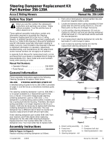
Control Lever and Seat Assembly
The seat is removed for ease in shipping and the control
lever’s upper bolts and flat washers are removed and the
levers are rotated down.
Refer to Figure 1-1:
1. Install the standard seat (#1) (or the optional
suspension seat) to the seat pan (#2) using four 5/16”
nuts (#3) and four 5/16” flat washers (#4).
2. Connecttheswitchwiresonthemowerwiththeswitch
wires on the seat. Secure the switch wires to the seat
pan (#2) using three wire ties (#5).
3. Fliptheseatoverintotheoperatingpositionandrotate
thecontrolleversupuntiltheholeslineupandreplace
the bolts and flat washers.
Remote Air Cleaner Assembly
Refer to Figure 1-2:
1. Slide air cleaner clamp (#1) over air cleaner housing
(#2), position the clamp so the bolt holes are facing
down (away from the intake) and the notches on the
clamp fit in the notches on the housing.
2. Insert air cleaner element (#3) inside air cleaner
housing (#2) and attach housing end (#4) (with the
arrows pointing up). Place rubber grommet (#5) over
opening in housing end (#4).
3. Attach air cleaner intake cap (#6) to the air cleaner
housing (#2) using a hose clamp (#7).
4. Attach air cleaner hose (#8) to the air cleaner (#2)
using a hose clamp (#7).
Refer To Figure 1-3:
5. Remove plastic cap from carburetor intake.
!
CAUTION!
Be careful to not allow any foreign material into the carburetor
while performing this assembly.
Seat Assembly
Figure 1-1
20858
Carburetor Intake
Figure 1-3
20859
Plastic Cap
Air Cleaner Assembly
Figure 1-2
20862

8
Section 1 Assembly and Set-Up
Z52®, Z60® & Z72® Zero Turning Radius Mowers Accu-Z 356-005M 03/11/03
Land Pride
Refer to Figure 1-4:
6. Insert the air cleaner hose through the hole in the air
cleaner hood and slide hose end over the carburetor
intake.
7. Secure air cleaner to the air cleaner hood with two 5/
16” bolts, four 5/16” flat washers and two 5/16” nuts.
8. Securehosetothe carburetorintakewith hoseclamp.
Optional Equipment Assemblies
Remote Air Cleaner Assembly
Refer to Figure 1-2 page 7:
The remote air cleaneris standard equipment on mowers
with Serial No. 364548 and above.
However, it may be purchased as an option on mowers
with Serial No. 364547 and below.
Control Lever Extensions
Refer to Figure 1-5:
1. Install the Extensions (#4) as shown.
Hose Clamp
5/16” Bolt
20860
Control Lever Assembly
Figure 1-5
19121
Figure 1-4
Air Cleaner

9
Section 1 Assembly and Set-Up
03/11/03
Z52®, Z60® & Z72® Zero Turning Radius Mowers Accu-Z 356-005M
Land Pride
Accu-Vac Assembly
Refer to Figure 1-9 on page 12
Land Pride offers as an option an Accu-Vac Collection
System designed to collect mower clippings into two 30
gallon rubber containers mounted on the back of the
mower.
!
WARNING!
Do not operateAccu-Vac System without remoteair cleanerset-
up or engine damage may occur.
!
WARNING!
Do not operate mower without deflector chute or Accu-Vac in
place.
Mower Deck Preparation
Refer to Figure 1-6:
Park the Accu-Z mower on a flat surface. Shut off the
ignition switch and remove the key from the switch.
Disconnect the negative battery cable.
Before the Accu-Vac can be installed, the right side pulley
cover (4) and discharge chute assembly (1) must be
removed. Loosen the tensioner for the blade belt and
remove pulley (7). Parts 2, 3, 6 and 8 will be used to
assemble Accu-Vac.
NOTE: Accu-Vac Collection System cannot be
mounted on Accu-Z mowers manufactured with
Honda engines. Use only with Kawasaki engines.
NOTE:Retainallotherpartsastheywillbere-installed
when the Accu-Vac is removed.
Chute, Pulley and Pulley Cover Removal
Figure 1-6
19907

10
Section 1 Assembly and Set-Up
Z52®, Z60® & Z72® Zero Turning Radius Mowers Accu-Z 356-005M 03/11/03
Land Pride
6. Install blower belt (#16) to double pulley and route it
as shown. (Belt must be on top pulley)
7. Assemble pulley cover (#17) using existing knobs
(#18).
Route Belt to
Top Pulley
Blower Belt
20855
Blower
Drive Belt
Blower, Pulley and Pulley Cover Assembly
Refer to Figure 1-7:
1. Install double pulley (#13) with the bolt (#11) and
existing flat washer (#12) Torque bolt 65 - 75 lbs.
2. Reinstall blade drive belt on lower grove of pulley
(13).
3. Assemble bracket (#4) where the chute bracket was
assembled using the existing hardware (#2) and
(#3).
4. Assemble blower pivot (#5) with carriage bolt (#6)
and existing hardware (#7), (#8), (#9) and (#10).
5. Install blower (#1) on blower pivot and swing blower
around and secure to bracketwithpin(#14)andhair
pin cotter (#15).
Blower Assembly
Figure 1-7

11
Section 1 Assembly and Set-Up
03/11/03
Z52®, Z60® & Z72® Zero Turning Radius Mowers Accu-Z 356-005M
Land Pride
Bagger Assembly
Refer to Figure 1-8:
1. Remove and retain rear bumper bolts (#3) and flat
washers (#4). Do not remove bumper.
2. Assemble left bracket (#1) and right bracket (#2)
through the same slots using the bolts and flat
washers retained from the bumper.
!
CAUTION!
Muffler can cause burning. Muffler should be cool before pro-
ceeding.
3. Position muffler deflector (#5) on existing muffler
exhaust so that deflector is pointing away from the
plasticcontainers.Markforholethroughdeflector(#5)
and drill hole for screw using a #26 (.147) drill bit.
4. Install muffler deflector to existing exhaust and fasten
with screw (#6) through hole in deflector and drilled
hole.
NOTE: Accu-Vac Collection System cannot be
mounted on Accu-Z mowers manufactured with
Honda engines. Use only with Kawasaki engines.
19910
Bagger Brackets and Muffler Deflector Assembly
Figure 1-8
Important
Damage will occur if:
Failure to install and/or adjust muffler exhaust deflector,
will result in damage to either grass catcher container or
mower.
With engine cool:
Install the muffler exhaust deflector onto current muffler
exhaust pipe.
Swivel deflector around so the exhaust is porting away
frombothunitandbagger.Startmowerand checkair flow
out of deflector. Make sure hot exhaust air is not diverted
onto unit or bagger. Exhaust should be diverted out to
side.
Mark muffler exhaust pipe using hole in diverter.
Drill muffler exhaust pipe using #26 (.147) drill bit.

12
Section 1 Assembly and Set-Up
Z52®, Z60® & Z72® Zero Turning Radius Mowers Accu-Z 356-005M 03/11/03
Land Pride
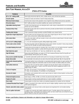
Z52 Left Side
19909
Front Lift and Weight Assembly
Figure 1-10
5. Install bagger (#1) through brackets and secure with
pins (#2).
6. Assembleclamps(#3) on the ends ofthebaggertube
(#4) and slide the tube over the bagger inlet and the
blower as shown in Figure 1-9 and tighten clamps.
NOTE: Lubricant can be used when installing tube to
bagger so the tube will slide over bagger inlet easier.
Bagger Assembly
Figure 1-9
19911
Front Lift and Weight Assembly
(For Blade Service or Replacement)
1. The front weight bracket (#1) will mount to the front of
the mower frame with the four u-bolts (#2) lock
washers(#3) andnuts(#4)on theZ60 &Z72mowers.
TheZ52mounts with twou-bolts (#2) ontherightside
and one bolt (#7) and nut (#4) on the left side of
frame as shown in Figure 1-10.
2. Fill the weight (#5) with sand and secure to
weight bracket with bolts (#8), lock washers (#9)
and flat washers (#10).
3. Assemble jack (#6) to the jack mount on the
weight bracket.
IMPORTANT: Do not use jack to support mower while
working under the deck. Chock back wheels and
securely block unit up before working under the deck.

13
Section 2 Operation
03/11/03
Z52®, Z60® & Z72® Zero Turning Radius Mowers Accu-Z 356-005M
Land Pride
Section 2
Operation
Controls
For general location of the controls described in this
section, refer to Figure 2-1.
Ignition Switch
Refer to Figure 2-2:
A three position switch: off, run, and start. With key
inserted, rotate it clockwise to START position; release
key when engine starts, and switch will automatically
return to the RUN position.
Throttle Control
Refer to Figure 2-2:
A cable is linked to engine throttle for controlling engine
speed. Move lever forward to increase engine rpm, move
lever rearward to decrease engine rpm.
Choke Control
Refer to Figure 2-2:
A cable is linked to manually operate the engine choke.
When the lever is in the down position, the choke is in the
off(run)position.When the leverispulledup, the chokeis
in the on (start) position. DO NOT operate the machine in
the on (start) position.
Control Panel
Figure 2-2
Ignition Switch
Blade Engagement
Switch
Oil Pressure
Light
Throttle
19097
Choke
1. Ignition Switch
2. Throttle Lever
3. Control Levers
4. Blade Engagement
Switch
5. Deck Lift Pedal
6. Hour Meter
7. Oil Pressure Light
8. Fuel Tanks
9. Hydraulic Reservoir
10. Battery
11. Deck Adjusting Rod
12. Anti-Scalp Wheels
13. Discharge Chute
14. Left Belt/Pulley Cover
15. Right Belt/Pulley Cover
16. Deck Height Indicator
17. Brake Switch
18. Choke Lever
Accu Z Controls
Figure 2-1
19058

14
Section 2 Operation
Z52®, Z60® & Z72® Zero Turning Radius Mowers Accu-Z 356-005M 03/11/03
Land Pride
Left/Right Fuel Tank Valve
Refer to Figure 2-3:
The mower is equipped with a Left/Right Fuel Tank Valve
that will determine which fuel tank the mower is operating
from.Itis notimportantwhich fueltankthe mowerisusing.
Blade Engagement Switch
Refer to Figure 2-2:
Thisswitchengagesthedeckblades.Pull theswitch upto
engage and push switch down to disengage the clutch.
Control Levers
Parking Brake
The Parking Brakes are applied by moving the control
leversfromtheNeutralPosition(Figure2-5)toanoutward
position (Refer to Figure 2-4). Each rear wheel brake
operates independently of the other.
!
WARNING!
In the event of a system failure while mowing, engage both
parking brakes to stop or slow mower. Refer to Figure 2-4.
Refer to Figure 2-5:
Theseleverscontrolthemower’s speed,direction,neutral
lock and park brake. Levers are used to steer,accelerate,
brake and change direction. The mower will not move
when the engine is on, drive pumps are operating and the
control levers are in the park brake position (out)
Figure 2-4.
!
WARNING!
The parking brake is not designed to hold the mower on steep
slopes.
Deck Lift Pedal
Refer to Figure 2-6:
Thedecklift pedal isusedto raiseorlower the deck.Push
on the pedal to raise the deck and then place the deck
height locking pin into the desired cutting height hole.
Push the deck lift pedal to raise the deck when going over
obstructions.
Left/Right Fuel Tank Switch
Figure 2-3
IMPORTANT: Never engage clutch with engine
running at high rpm or when the deck is under load.
Clutch, belts or deck could be damaged.
Control Levers in Parking Brake Position
Figure 2-4
19698
Control Levers
Figure 2-5
Control Levers
19060
Deck Lift
Pedal
Deck Lift Pedal
Figure 2-6
19061
Deck Height
Locking Pin

15
Section 2 Operation
03/11/03
Z52®, Z60® & Z72® Zero Turning Radius Mowers Accu-Z 356-005M
Land Pride
Instrumentation
Electronic Hour Meter
Refer to Figure 2-7:
Registers 1/10 hour increments up to 9,999.9 total hours.
Connected to the ignition switch, the meter records the
accumulative time while the ignition key is switched to the
RUN position and the operator is on the seat.
Oil Pressure Light
Refer to Figure 2-2:
This light comes on when the ignition switch is placed in
the RUN position and stays lit until the engine is running
and a safe oil pressure is developed. If light comes on
during operation, shut engine off immediately and locate
and correct the problem.
Safety Start Interlock System
Themowerisequippedwithasafetystartinterlocksystem
consisting of the brake switches, seat switch, and deck
clutch switch. Check mower safety start interlock system
daily, prior to operation. This system is an important
mower safety feature. It should be repaired immediately if
itmalfunctions.Themachineincorporatesaseparateseat
switch which will stop the mower engine when the
operator is unseated for any reason while the mower is
moving or the deck clutch is engaged. This is a safety
feature designed to prevent runaway or accidental
entanglement. To inspect the system:
1. The operator must be on the seat when testing the
seat switch.
2. Set both control levers in the park brake position.
3. Start the engine and allow it to warm up to operating
temperature.
4. With the deck clutch switch down and the control
leversinthe park brakeposition,slowlyraiseoff ofthe
seat. The engine should continue to run.
5. With the deck clutch switch up and/or the control
levers in the neutral position, slowly raise off of the
seat. The engine should stop within two seconds.
6. If the engine fails to stop when the deck clutch switch
is up or one or both of the control levers is in and the
operator is off the seat, check the function of the seat
switch. If the seat switchisnotoperating properly and
if the cause can not be determined, replace the seat
switch.
Iftheproblem can notbelocated,contact your LandPride
Dealer.
!
WARNING!
The safety interlock system should always function per steps 4
and 5. If it does not function properly, it should be corrected
immediately. Do not operate the mower without a properly
functioning seat safety switch.
!
WARNING!
The safety interlock system must not be disconnected or
bypassed.
Engine Starting
The Accu Z safety start interlock system is also designed
to protect the operator and others from accidental injury
due to unintentional engine starting. The engine starting
motor will not engage until:
A. Control levers are in the brake position.
B. Deck clutch switch is in the down (OFF) position.
Thefollowingsteps are thecorrectprocedures forstarting
the engine. If difficulty is encountered, contact the Land
Pride Dealer in your area.
1. Before starting mower each day, perform daily pre-
operation checking.
2. Make sure the control levers are in the brake position
and deck clutch switch is disengaged.
3. Set throttle at approximately 1/2 open position.
4. Insert keyin ignition switchand rotate fullclockwiseto
engage starting motor. Release key when engine
starts.
Hour Meter
Figure 2-7
Hour Meter
19062
NOTE: The operator’s seat is equipped with a
separate safety switch. If for any reason the operator
should become unseated when the neutral switches
are disengaged or the deck clutch switch is engaged
the engine will stop.
NOTE: Use choke position when engine is cold, or if
warm engine fails to start within 5 seconds of
cranking. Avoid flooding and operate engine without
choking as soon as possible.

16
Section 2 Operation
Z52®, Z60® & Z72® Zero Turning Radius Mowers Accu-Z 356-005M 03/11/03
Land Pride
5. Performtesttomakesuresafetystartinterlocksystem
is operating properly. Refer to Safety start interlock
system section.
6. As soon as engine begins to run, check to make
certain the oil warning light is off. If not, stop engine
immediately and check for the cause.
7. Allow the engine to idle a few minutes before
advancing the throttle and/or engaging the deck
clutch.
8. Before stopping theengine,place thecontrolleversin
the brake position, disengage the deck clutch, and
throttle back to low idle for a couple of minutes; then
rotate ignition key counter-clockwise to the OFF
position. Remove the key from switch before leaving
the seat.
!
WARNING!
Never leave the machine unattended with key in ignition switch.
Moving Mower with Stalled Engine
If it becomes necessary to move the mower when the
engine is inoperative, the hydraulic pumps are equipped
with bypass valves. Before moving the unit, turn bypass
valves counter clockwise one-half to one revolution. The
valve stems on each hydraulic pump are located near the
top and are identified as a hex stud. Refer to Figure 2-8.
Donottow themachine.Move itbyhand orusea winchto
load on a trailer for transporting.
IMPORTANT: The engine starter should not be
operatedforperiodslongerthen 30 secondsata time.
An interval of at least two minutes should be allowed
between such cranking periods to protect the starter
from overheating and burn-out.
19064
Bypass Valve
Figure 2-8
Bypass
Valve
IMPORTANT: Always make certain the two bypass
valves are returned to their operating position before
running the mower following repairs.
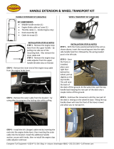
Steering
Figure 2-9
Front of mower Faces This Direction
N
N
Forward Travel Pivot Right Turn Forward Travel
Right Turn
Reverse Travel
Right Turn
Reverse Travel
N= Neutral Position
Direction of arrows indicate direction of mower movement.

17
Section 2 Operation
03/11/03
Z52®, Z60® & Z72® Zero Turning Radius Mowers Accu-Z 356-005M
Land Pride
Driving the Mower
!
DANGER!
Never make sudden stops or reverse direction, especially when
going down a slope. The steering is designed for sensitive
response. Rapid movement of the control levers in either
direction could result in a reaction of the mower that can cause
serious injury.
Steering
Refer to Figure 2-9:
After starting engine, engage the control levers and steer
as follows:
To Go Forward:
Push control levers forward an equal distance.
To Go in Reverse:
Pull control levers rearward an equal distance.
To Turn Left:
Move the right control lever farther forward from neutral
than the left control lever.
To Turn Right:
Move the left control lever farther forward from neutral
than the right control lever.
To Pivot Turn:
Moveonecontrol lever forwardandthe other controllever
back of neutral, this will allow the drive wheels to counter-
rotate.
To Stop or Decrease Speed
!
WARNING!
In the event of a system failure while mowing, engage both
parking brakes to stop or slow mower. Refer to Figure 2-4.
Move control levers to neutral. When going forward pull
backgentlyon controllevers. Whengoingin reversepush
forward gently on control levers.
!
DANGER!
When going in reverse push forward gently on control levers
and avoid sudden movement. Any sudden movement could
cause the front of the mower to come off of the ground resulting
in possible loss of control.
To Increase Speed
Increase control levers equal distance from neutral. The
farther forward control levers are from neutral, the faster
mower will travel forward. The farther back control levers
are from neutral, the faster mower will go in reverse.
Operating Suggestions
!
DANGER!
Priortooperatingthemowerthe operatorshouldbethoroughly
familiar with the proper use and operation of the equipment,
should read the manual completely and thoroughly, and should
haveattemptedslow movingmaneuverstobecomefamiliarwith
the operation of the equipment before attempting normal speed
operation.An inexperiencedoperatorshould not mow on slopes
or on uneven terrain.
!
WARNING!
The mower’s control levers are very responsive: Easy does it!
For smooth operation, move lever slowly, avoid sudden
movement. Skill and ease of operation come with practice and
experience.
Inexperienced operators may have a tendency to
over-steer and lose control. Slow-moving practice
maneuvers are recommended to become familiar with
these characteristics before attempting normal speed
operation.
!
WARNING!
Sharpdepressionsorraisedobstacles(suchas gutters or curbs)
should not be directly approached at high speed in an attempt
to jump them as the operator could be thrown from the
equipment.Approachata slow speed and angleone drive wheel
at the obstruction. Continue at an angle until the wheel clears
and then pivot the opposite wheel around.
When turning on soft wet turf, keep both wheels rolling
either forward or backward. Pivoting on one stopped
wheel can damage turf.This is especially important when
mowing.
Peakmowingperformanceismaintainedwhenthethrottle
is set at full rpm. This gives maximum power to the drive
wheels and deck when needed. Use the control levers to
control ground speed rather than engine rpm.
!
WARNING!
Do not operate the equipment while wearing sandals, tennis
shoes, sneakers, shorts or any type of loose fitting clothing.
Always wear long pants, safety glasses and safety shoes when
operating this machine.
Keep blades sharp. Many professional mowing
companies have additional sets of blades and change
blades twice a day: once in the morning and again at
noon. Many problems with incorrect cutting patterns are
due to dull blades or blades which have been sharpened
incorrectly. Information on sharpening blades is listed in
this manual’s maintenance section. In addition, most
communities have individuals or companies which
specialize in sharpening mower blades. Blade sharpness
should be checked daily.

18
Section 2 Operation
Z52®, Z60® & Z72® Zero Turning Radius Mowers Accu-Z 356-005M 03/11/03
Land Pride
Use high blade speed. Your Accu Z is designed to
operate at full throttle. The throttle settingdirectlycontrols
bladespeed.The highestbladespeed generally givesthe
best cut.
Direct grass discharge to right, away from unmown
area.Selectamowingpatternthatdirectsgrassdischarge
towards the outside, not towards center, of mowing area.
Generally, this means using a pattern utilizing left turns
becausesidedischarge istoright. RefertoFigure 2-10.In
any case, avoid throwing grass discharge onto unmowed
area because grass is then mowed twice. Mowing twice
putsanunnecessaryloadontheunitandreducesmowing
efficiency.
!
WARNING!
Never direct discharge of material from mower deck towards
bystanders.
!
WARNING!
Never operate the mower deck with discharge chute removed or
in raised position.
!
WARNING!
Always check area to be mowed for rocks and other debris
before mowing.
Mower Deck Operation
!
DANGER!
Neverattemptto make any adjustmentstothe mower deckwhile
the engine is running or with the blade engagement switch
engaged. Mower blades cannot be seen and are located very
close to deck housing. Fingers and toes can be cut off instantly.
With the engine running, engage the blade engagement
switch (Refer to Figure 2-11) and advance engine throttle
to full rpm.
Blade Engagement Switch
Figure 2-11
Discharge Chute
Figure 2-10
Discharge
Chute
19065
NOTE: Engaging the blade engagement switch at
high engine rpm or when under heavy load (in tall
grassforexample)can causebeltstoslip,resultingin
premature wear or possible damage.
Blade Engagement
Switch
19059
/