Page is loading ...

Avaya
Installation and Maintenance Guide
AVAYA P460
MULTILAYER MODULAR SWITCH
SOFTWARE VERSION 1.0
February 2003


Avaya P460 Installation and Maintenance Guide i
Contents
List of Tables....................................................................................................... v
List of Figures .................................................................................................. vii
Preface Before you Install the Avaya™ P460................................................................ I
Safety Information .............................................................................................. I
Power Supplies ........................................................................................I
FCC Notice......................................................................................................... II
Conventions Used in the Documentation ..................................................... II
Notes, Cautions and Warnings ............................................................ II
CLI Conventions ...................................................................................III
Warranty ........................................................................................................... III
Notice................................................................................................................. III
Avaya Support ................................................................................................. III
Chapter 2 Avaya P460 Overview....................................................................................... 1
Introduction ........................................................................................................ 1
Avaya P460 Key Features: ................................................................................ 2
High Availability .................................................................................... 2
Flexibility ................................................................................................. 2
Management and Monitoring ............................................................... 2
Chapter 3 Avaya P460 Chassis and Module Installation ............................................... 3
Introduction ........................................................................................................ 3
Operating Safety ................................................................................................ 3
Required Tools ................................................................................................... 4
Environmental Prerequisites............................................................................ 4
Chassis Component Location........................................................................... 6
Installing the P460 on a Table Top .................................................................. 7
Rack Mounting ................................................................................................... 7
P460 Rack mounting procedure: .......................................................... 9
Cable Guide Installation ................................................................................. 10
PSU (Power Supply Unit) Installation .......................................................... 11
Fan Module Replacement or Installation ..................................................... 12
Supervisor Module Installation ..................................................................... 14
I/O Module Installation.................................................................................. 16
I/O Module Installation Procedure ................................................... 17
Chapter 4 Turning on the Avaya P460............................................................................ 19

Table of Contents
ii Avaya P460 Installation and Maintenance Guide
Introduction ...................................................................................................... 19
Installing a PSU ................................................................................................ 19
Powering Up ..................................................................................................... 20
Turning on a Chassis with Supervisor and I/O Modules
Already Inserted ...................................................................................20
Turning on a Chassis with a Supervisor Module Only ...................20
Turning on a Chassis with no Modules .............................................20
Inserting an Additional PSU........................................................................... 20
Removing or Switching off a PSU.................................................................. 21
If there is one PSU .................................................................................21
If there are two PSUs ............................................................................21
If there are three PSUs ..........................................................................22
Power Management......................................................................................... 23
The Power Management Process ........................................................23
Chapter 5 Avaya P460 Panels ........................................................................................... 25
Introduction ...................................................................................................... 25
M460ML-SPV Panel ......................................................................................... 25
M460ML-SPV LEDs ..............................................................................25
ACT LED and OPR LED Summary ....................................................27
Function LEDs .................................................................................................. 28
M460ML-SPV Supervisor Module Ports....................................................... 31
Eth Port (Outband Connection) ..........................................................31
RS-232 Port (Sideband Connection) ...................................................31
M460ML-SPV Left and Right Pushbuttons .................................................. 31
M460ML-SPV ASB (Alternate Software Bank) Pushbutton....................... 32
Power Supply Panel......................................................................................... 33
Chapter 6 Maximizing Avaya P460 Availability ........................................................... 35
Introduction ...................................................................................................... 35
M460ML-SPV Supervisor Module Redundancy ......................................... 35
M460ML-SPV Supervisor Module Modes: .......................................35
Configuring the Supervisor Modules for Active/Standby
Operation ...............................................................................................36
Synchronizing the Supervisor Modules Manually ..........................36
Configuration File Synchronization ...................................................37
Redundant Power Supplies ............................................................................ 39
Calculating the Power Budget ............................................................40
Chapter 7 Establishing Switch Access............................................................................. 41
Introduction ...................................................................................................... 41
Establishing a Console Connection with the P460 ...................................... 41
Establishing a Telnet Connection with the Switch (Inband)...................... 42
Inband Interface Connection CLI Commands ..................................42
Establishing a Telnet Connection with the Switch (Outband) .................. 43

Table of Contents
Avaya P460 Installation and Maintenance Guide iii
Outband Interface Connection CLI Commands .............................. 44
Redundant Outband Connections .....................................................45
Establishing a PPP via Modem Connection with the P460 (Sideband) ... 46
Overview ................................................................................................ 46
Sideband (PPP) Interface CLI Commands ........................................ 46
Setting Up Sideband (PPP) Connection Configuration .................. 47
Chapter 8 Avaya MSNM P460 Manager......................................................................... 49
PC System Requirements for Running the Avaya MSNM P460
Manager............................................................................................................. 49
Running the Avaya MSNM P460 Manager.................................................. 50
Installing the Java Plug-in............................................................................... 52
Installing the On-Line Help and Java Plug-In on your Web Site.............. 53
Documentation................................................................................................. 53
Chapter 9 User Authentication......................................................................................... 55
Introduction ...................................................................................................... 55
Local User Accounts........................................................................................ 55
Access Levels ......................................................................................... 55
Local User Account CLI Commands ................................................. 56
RADIUS............................................................................................................. 57
Introduction to RADIUS ...................................................................... 57
RADIUS CLI Commands .................................................................... 58
Allowed Managers........................................................................................... 60
Allowed Manager CLI Commands .................................................... 60
Chapter 10 Configuration Defaults ................................................................................... 61
Introduction ...................................................................................................... 61
Default System Parameters ............................................................................ 61
Configuration Default CLI Commands ............................................. 62
Chapter 11 Basic Switch Configuration ............................................................................ 63
Introduction ...................................................................................................... 63
System Parameter Configuration ....................................................... 64
Identifying the system .........................................................................64
Operating parameters .......................................................................... 64
Time Parameter Configuration ...................................................................... 65
Feature License Configuration....................................................................... 65
Feature Activation ................................................................................ 65
Obtaining a License Key ...................................................................... 66
Activating a Routing License Key ...................................................... 68
Feature License CLI Commands ........................................................68
Chapter 12 Troubleshooting the Installation.................................................................... 69
Introduction ...................................................................................................... 69

Table of Contents
iv Avaya P460 Installation and Maintenance Guide
Powering up the Chassis ......................................................................69
Powering up the Supervisor Modules ...............................................69
Powering up the Fan Module .............................................................69
Powering up the I/O Modules ...........................................................70
Supervisor Module does not Boot ......................................................71
Chapter 13 Maintenance...................................................................................................... 73
Introduction ...................................................................................................... 73
Replacing I/O Modules................................................................................... 73
Replacing Supervisor Modules ...................................................................... 73
One Supervisor Module in the Switch ...............................................73
Two Supervisor Modules in the Switch .............................................73
Configuring the Supervisor Modules for Active/Standby
Operation ....................................................................................73
Firmware Download........................................................................................ 74
Introduction ...........................................................................................74
Preferred Bank .......................................................................................74
Booting from the Alternate Firmware Bank ..........................74
Firmware Download CLI Commands ...............................................75
Configuration File Management.................................................................... 75
Configuration Management CLI Commands ...................................75
Chapter 14 Standards........................................................................................................... 77
Introduction ...................................................................................................... 77
IEEE .........................................................................................................77
IETF .........................................................................................................77
Layer 2 .........................................................................................77
Layer 3 .........................................................................................78
Routing ...................................................................................................78
Chapter 15 Specifications .................................................................................................... 79
Physical .............................................................................................................. 79
Power Requirements........................................................................................ 80
MPS4603-AC Power Supply ....................................................80
Components ...............................................................................80
Environmental .................................................................................................. 80
Safety.................................................................................................................. 80
EMC Emissions................................................................................................. 81
Immunity ................................................................................................81
Transportation .......................................................................................81
Catalog Numbers ............................................................................................. 82

Avaya P460 Installation and Maintenance Guide v
List of Tables
Table 3.1 Environmental Requirements.....................................................4
Table 3.2 AC Power Requirements.............................................................5
Table 3.3 Dimensions.................................................................................... 5
Table 5.1 Active M460ML-SPV LEDs....................................................... 25
Table 5.3 Standby/Halted M460ML-SPV LEDs .....................................26
Table 5.2 Active M460ML-SPV FastETH LED........................................ 26
Table 5.5 ACT and OPR LED Summary.................................................. 27
Table 5.4 Standby M460ML-SPV FastETH LED.....................................27
Table 5.6 M460ML-SPV Function LEDs................................................... 29
Table 5.7 M460ML-SPV Left and Right Pushbutton Functions............ 31
Table 5.8 Power Supply Status LED.........................................................33
Table 6.1 ACT and OPR LED Summary.................................................. 35
Table 6.2 Sample Power Budget Calculation .......................................... 40
Table 9.1 Access Level Descriptions......................................................... 55
Table 10.1 Default System Parameters....................................................... 61
Table 15.1 Avaya P460 Catalog Numbers ................................................. 82

List of Tables
vi Avaya P460 Installation and Maintenance Guide

Avaya P460 Installation and Maintenance Guide vii
List of Figures
Figure 3.1 The Avaya P460 Switch – Component Location ..................... 6
Figure 3.2 Table-Top Installation.................................................................. 7
Figure 3.3 P460 Front-Mount and Mid-Mount Positions (side view) ..... 8
Figure 3.4 Positioning the rack-mounting brackets...................................9
Figure 3.5 Installing the Cable Guide ........................................................10
Figure 3.6 The Avaya P460 Switch – Fan Module Location ................... 12
Figure 3.7 Installing the Avaya P460 Fan Module ...................................13
Figure 3.8 Location of the Avaya P460 Supervisor Modules ................. 14
Figure 3.9 Installing the P460 Supervisor Module...................................15
Figure 3.10 Lcoation of Avaya P460 I/O Modules ....................................16
Figure 3.11 I/O Module Component Location........................................... 17
Figure 3.12 Installing P460 I/O Modules....................................................18
Figure 4.1 Power Allocation after PSU Removal .....................................21
Figure 4.2 Power Management Priority ....................................................23
Figure 4.3 I/O Module Power Management Process..............................24
Figure 5.1 M460ML-SPV LEDs ................................................................... 25
Figure 5.2 M460ML-SPV Function LEDs................................................... 28
Figure 5.3 Function LEDs Cycle ................................................................. 28
Figure 5.4 M460ML-SPV Supervisor Module Console Ports ................. 31
Figure 5.5 P460 Supervisor Module Left and Right Pushbutton ...........31
Figure 5.6 P460 Supervisor Module ASB Pushbutton............................. 32
Figure 7.1 M460ML-SPV Supervisor Module Serial Console Port........ 41
Figure 7.2 M460ML-SPV Supervisor Module Fast Ethernet Console
Port ............................................................................................... 43
Figure 7.3 Redundant Outband Connections...........................................45
Figure 8.1 The Welcome Page..................................................................... 50
Figure 8.2 P460 Device Manager ................................................................51
Figure 9.1 RADIUS Authentication Procedure ........................................58

List of Figures
viii Avaya P460 Installation and Maintenance Guide

Avaya P460 Installation and Maintenance Guide I
Before you Install the Avaya™ P460
Safety Information
Caution: The Avaya P460 switch and modules contain components sensitive to
electrostatic discharge. Do not touch the circuit boards unless instructed to do so.
Caution: Do not leave any slots open. Use the the blanking plates supplied to cover
empty slots.
Caution: Do not insert any objects into the P460 chassis other than specifically
designed Avaya products.
Warning: The fans are on whenever the power is on in the chassis, whether
supervisor modules are installed or not.
Warning: Keep your fingers and other objects clear of the fans when removing the
Fan module. The fans continue to turn briefly after you have removed the module.
Power Supplies
Caution: Risk of electric shock. Disconnection of one power supply cord disconnects
one power supply module only. To isolate unit completely from the mains
disconnect all power supply cords.
Preface

Preface
II Avaya P460 Installation and Maintenance Guide
Caution: Gafahr des elektrischen Schocks. Entfernen des Netzsteckers eines
Netzteils legt nur dieses Netzteil spannungsfrei. Um alle Einheiten spannungsfrei
zu machen. Sind die Netzstecker aller Netxteile zu entfernen
Caution: Risque d'électrocution. Le débranchement d'un câble d'alimentation ne
déconnecte qu'un seul module d'alimentation. Pour isoler complètement l'unité du
secteur, débranchez tous les câbles d'alimentation.
FCC Notice
This equipment has been tested and found to comply with the limits for a Class A
digital device, pursuant to part 15 of the FCC Rules. These limits are designed to
provide reasonable protection against harmful interference when the equipment is
operated in a commercial environment. This equipment generates, uses, and can
radiate radio frequency energy and, if not installed and used in accordance with the
instruction manual, may cause harmful interference to radio communications.
Operation of this equipment in a residential area is likely to cause harmful
interference in which case the user will be required to correct the interference at his
own expense.
Changes or modifications to this equipment not expressly approved by Avaya Inc.
could void the user’s authority to operate the equipment.
Conventions Used in the Documentation
Documentation for this product uses the following conventions to convey
instructions and information:
Notes, Cautions and Warnings
L Text with the L symbol contains helpful information or hints or reference to
material in other documentation.
Caution: Take care. You could do something that may damage equipment or result
in loss of data.

Preface
Avaya P460 Installation and Maintenance Guide III
Warning: This means danger. Failure to follow the instructions or warnings might
result in bodily injury. Ensure that you are qualified for this task and have read and
understood all the instructions
CLI Conventions
• Mandatory keywords are in the computer bold font.
• Information displayed on screen is displayed in computer font.
• Variables that you supply are in pointed brackets <>.
• Optional keywords are in square brackets [].
• Alternative but mandatory keywords are grouped in braces {} and separated by
a vertical bar |.
• Lists of parameters from which you can choose are enclosed in square brackets
[ ] and separated by a vertical bar |.
• If you enter an alphanumeric string of two words or more, enclose the string in
inverted commas””.
Warranty
Avaya Inc. provides a limited warranty on this product. Refer to your sales
agreement or other applicable documentation to establish the terms of the limited
warranty. In addition, Avaya’s standard warranty language as well as information
regarding support for this product, while under warranty, is available through the
following website: http://www.support.avaya.com.
Notice
Every effort was made to ensure that the information in this document was
complete and accurate at the time of printing. However, information is subject to
change.
Avaya Support
Avaya provides a telephone number for you to use to report problems or to ask
questions about your contact center. The support telephone number is 1-800-242-
2121 in the United States. For additional support telephone numbers, see the Avaya
Web site: http://www.avaya.com
Select Support, then select Escalation Lists. This Web site includes telephone
numbers for escalation within the United States. For escalation telephone numbers
outside the United States, select Global Escalation List.

Preface
IV Avaya P460 Installation and Maintenance Guide

Avaya P460 Installation and Maintenance Guide 1
Chapter 2
Avaya P460 Overview
Introduction
The Avaya™ P460 is a flexible six-slot modular chassis, with two slots reserved for
supervisor modules and the four remaining slots for switched I/O modules. It is
ideal as a LAN edge and wiring closet switch for SMEs or as an “all-in-one” solution
for branch offices. You can also deploy the Avaya P460 in data centers or as a
distribution switch.

Chapter 2 Avaya P460 Overview
2 Avaya P460 Installation and Maintenance Guide
Avaya P460 Key Features:
High Availability
• Redundant Supervisor modules
• Redundant switching fabric
• Three power supply bays that support redundant (optional), load-sharing and
fault-tolerant AC power supplies.
• Hot-swappable fan module
• Hot-swappable supervisor modules
• Hot-swappable I/O modules
• Meets requirements for device redundancy, link resiliency and network
availability.
• Access to all components from the front of the chassis.
Flexibility
• Broad range of I/O modules, including
— 48 10/100 ports
— 48 10/100 ports + 2 Gigabit Ethernet ports
— 12 Gigabit Ethernet ports.
• Modular chassis flexibility with a variety of module/speed mixes.
• Upgradeable to Layer 3 switching with an optional license
Management and Monitoring
• Built-in Web-based device manager
• Avaya™ Multiservice Network Manager suite (optional)
• Standards-based SMON Switch Monitoring (optional, requires license)

Avaya P460 Installation and Maintenance Guide 3
Chapter 3
Avaya P460 Chassis and Module Installation
Introduction
This chapter guides you through the basic hardware Installation process.
L If you purchased an Avaya P460ML-CFG (Material code 700255003, PEC Code
4548-009), then one Supervisor Module, PSU and the Fan Module are already
installed.
Operating Safety
Caution: The Avaya P460 switch and modules contain components sensitive to
electrostatic discharge. Do not touch the circuit boards unless instructed to do so.
Use appropriate anti-static equipment when handling the switch and modules.
Caution: Do not leave any slots open. Use the the blanking plates supplied to cover
empty slots.
Caution: Do not insert any objects into the P460 chassis other than specifically
designed Avaya products.
Warning: Keep your fingers and other objects clear of the fans when removing the
Fan module. The fans continue to turn briefly after you have removed the module.
Danger: Keep your fingers and other objects clear of the fans when removing the
tray as the fans continue to turn briefly after you have removed it.

Chapter 3 Avaya P460 Chassis and Module Installation
4 Avaya P460 Installation and Maintenance Guide
Required Tools
You require the following equipment in order to install the P460 chassis:
• Phillips (cross-blade) screwdriver
Environmental Prerequisites
Danger: To avoid injury, Avaya recommends that two people lift the switch onto a
table top. A fully loaded P460 switch weighs at least 100 lbs (45 kg).
You can position the Avaya P460 in free-standing mode on a suitable shelf or table,
or mount it in a standard 19-inch equipment rack in a wiring closet or equipment
room.
When deciding where to position the chassis, ensure that:
• It is accessible and cables can be connected easily and according to the
configuration rule.
• Cables are away from sources of electrical noise such as:
— radio transmitters
— broadcast amplifiers
—power lines
— fluorescent lighting fixtures.
• Water or moisture cannot enter the case of the chassis.
• There is a free flow of air around all sides the chassis.
• The vents on the sides of the case are not blocked.
• The table or shelf can hold the weight of the chassis with the PSUs and modules.
• The environmental conditions match the requirements listed in Table 3.1.
L See Chapter 15, “Specifications“ for additional information.
Table 3.1 Environmental Requirements
Ambient temperature 23
o
to 122
o
F (-5
o
to 50
o
C)
Relative humidity 5% to 95%, non condensing
Minimum clearance for
ventilation
2" (5 cm) on each side
Weight support 50 lb. (23 kg) to 100 lbs (45 kg)

Chapter 3 Avaya P460 Chassis and Module Installation
Avaya P460 Installation and Maintenance Guide 5
• The power source matches the specifications shown in Table 3.2.
Table 3.3 Dimensions
Table 3.2 AC Power Requirements
Voltage 100 to 240 VAC, 50/60 Hz
Current for one Avaya
MPS4603-AC
300 W PSU
3.9 A@100 VAC
1.5 A@200VAC
Height 10U (17.5", 444.5 mm)
Width 17.4" (442 mm)
Depth 15" (375 mm)

Chapter 3 Avaya P460 Chassis and Module Installation
6 Avaya P460 Installation and Maintenance Guide
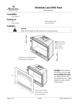
Chassis Component Location
Figure 3.1 shows the positions of the components in the P460 chassis.
Figure 3.1 The Avaya P460 Switch – Component Location
Key
1Supervisor modules
2I/O Modules
3PSUs
4Fan module
1
2
3
4
/