Page is loading ...

1 Image Vault
®
PRO Command
Image Vault, LLC
101 Security Parkway — New Albany IN 47150-0559
Ph 888.462.4382 — Fax 812.296.0038
www.image-vault.com
This manual supports Image Vault PRO Command Digital Video Recorders
(DVR). It includes hardware and software information. It is designed to aid in
installation and operation of your PRO Command DVR. Refer also to your Quick
Reference Guide, your built-in software help system, and check our web site
for the latest updates. Please read this manual thoroughly before installing and
conguring your Image Vault PRO Command recorder.
PRO COMMAND
Image Vault
®
is a registered trademark of Image Vault, LLC.
Other trademarks are property of their respective companies.
Version 10.x Edition

2 Image Vault
®
PRO Command
TABLE OF CONTENTS
Scope of This Manual ............................................................................................ 4
PART I - HARDWARE ............................................................................................. 5
1 Before Installation ..................................................................................... 6
1.1 Warnings ................................................................................................................................6
1.2 Physical Inventory ..............................................................................................................6
2 Facilities ...................................................................................................... 7
2.1 Front Panel ............................................................................................................................ 7
2.2 Rear Panel..............................................................................................................................8
3 Connecting System Components ............................................................. 9
3.1 4 Camera/30 FPS Model: Video & Audio Capture, Monitor Output ..............9
3.2 4 Camera/120 FPS Model: Video & Audio Capture, Monitor Output ...........9
3.3 8 Camera/60 FPS Model: Video & Audio Capture, Monitor Output ............10
3.4 8 Camera/240 FPS Model: Video & Audio Capture, Monitor Output .........10
3.5 16 Camera/120 FPS Model: Video & Audio Capture, Monitor Output .......11
3.6 16 Camera/480 FPS Model: Video & Audio Capture, Monitor Output .......12
3.7 32 Camera/240 FPS Model: Video & Audio Capture, Monitor Output .......13
3.8 IP Cameras ..........................................................................................................................14
3.9 SVGA Video Output: Security Monitor .....................................................................14
3.10 PTZ Control / Alarm Output .........................................................................................14
3.11 External Inputs ...................................................................................................................15
3.12 Interfacing POS Devices .................................................................................................15
3.13 USB Storage Devices ........................................................................................................21
3.14 Remote Playback PC to DVR Communication ......................................................21
4 Initialization ............................................................................................. 24
4.1 Positioning ..........................................................................................................................24
4.2 Power ....................................................................................................................................24
4.3 How to Check If the System is Working Properly ................................................24
4.4 CD-R or DVD-R Disk ........................................................................................................25
4.5 Troubleshooting Installation ........................................................................................25
4.6 HardwareSpecications ................................................................................................25
PART II - SOFTWARE ............................................................................................ 26
1 Specications&Requirements .............................................................. 27
1.1 DVRSoftwareSpecications ........................................................................................27
1.2 PRO-Command Remote Software Requirements................................................27
2 Software on the DVR ............................................................................... 28
2.1 Live Status Mode ..............................................................................................................28
2.2 Live Monitor Mode ..........................................................................................................30
2.3 Playback Mode ..................................................................................................................32
3 Software on Your PC ............................................................................... 34
3.1 Installing PRO-Command Playback ..........................................................................34
3.2 ModemConguration ....................................................................................................35
3.4 Network Communication ..............................................................................................35
3.5 Opening Copied Video ..................................................................................................38
4 Playback Operation ................................................................................. 39
4.1 Playing Video .....................................................................................................................39
4.2 Playing Audio .....................................................................................................................41

3 Image Vault
®
PRO Command
4.3 Transaction Data ...............................................................................................................41
4.4 Audit Data ...........................................................................................................................42
4.5 Error Log ..............................................................................................................................43
4.6 Skins .......................................................................................................................................43
4.7 QuickView Action Buttons ............................................................................................44
4.8 Camera Window Behavior ............................................................................................45
5 Evidence Management ............................................................................ 46
5.1 Catalog .................................................................................................................................46
5.2 Range Lock ..........................................................................................................................47
5.3 Blocked ranges..........................................................................................................................47
5.4 Copying Video to External Media ..............................................................................47
5.5 Download Video to Remote PC ..................................................................................48
5.6 Print Image ..........................................................................................................................48
5.7 Export Image ......................................................................................................................48
5.8 Export Clip ...........................................................................................................................48
6 User Management ................................................................................... 49
6.1 User Security ......................................................................................................................49
6.2 User Inactivity Timeouts ................................................................................................50
6.3 User Performance .............................................................................................................50
7 Recording Setup ...................................................................................... 52
7.1 Global Recording Settings ............................................................................................52
7.2 Camera Setup & Forced Recording Options .........................................................53
7.3 Motion Detection Triggered Recording ..................................................................55
7.4 External Input (Dry Contact) Triggered Recording ..............................................57
7.5 Data Device Setup ............................................................................................................59
7.6 Transaction Data Triggered Recording ....................................................................61
7.7 Alarm Output Setup ........................................................................................................63
System Setup .................................................................................................... 65
8.1 TCP/IP Settings ..................................................................................................................65
8.2 Location ................................................................................................................................66
8.3 System Clock ......................................................................................................................66
8.4 Clearing Logs .....................................................................................................................66
8.5 Record Monitor Setup ....................................................................................................67
8.6 SaveandLoadCongurationSettings.....................................................................67
8.7 Software Updates .............................................................................................................68
8.8 Screen Resolution.............................................................................................................68
8.9 Limit Recorder Days ........................................................................................................69
8.10 Backup Scheduler .............................................................................................................69
8.11 Shutdown/Reboot DVR ..................................................................................................70
Appendices ........................................................................................................... 70
A Troubleshooting ...............................................................................................................70
B Factory Defaults ...........................................................................................................................72
C System Audit Messages .................................................................................................73
D Legal Notices ......................................................................................................................74
E Warranty ..............................................................................................................................75
TABLE OF CONTENTS

4 Image Vault
®
PRO Command
SCOPE OF THIS MANUAL
This manual is designed to provide you with information necessary to install and
operate your PRO Command DVR. This manual assumes you have the appropri-
ate DVR for your application and all of the necessary supporting hardware such
as cameras, monitors, cables, etc. This manual supports both the standard and
high speed models. All information applies to both types, regardless of the num-
ber of cameras or hard drive capacity, except where noted.
The software (local and remote) includes a built-in help system which may be
accessed at any time from the Help menu. Built-in help is the most complete
and up to date resource available. This manual does not attempt to provide the
same level of detail about the software. Another resource available is the Quick
Reference Guide included with your DVR. For further information or to obtain the
latest version of remote playback software released, please visit our web site:
www.image-vault.com
Image Vault PRO Command

5 Image Vault
®
PRO Command
PART I
HARDWARE
There are two types of capture cards, standard and high speed, available for PRO
CommandDVRs.Cameracapturespeedsareindependentlycongurableupto
30 fps per camera. Actual capture rates may be limited when using standard cap-
ture cards. The camera and microphone inputs and public view monitor output
congurationdependsonthespecicmodel.
A unit with standard video capture cards can store up to 30 fps per four-camera
capture card or 120 fps total for a 16-camera model. Standard capture card mod-
els offer one microphone input for every 4 camera inputs.
High-speed units support the full 30 fps on every camera. In other words, a high-
speed 16-camera input is capable of capturing and storing up to 480 fps total.
The high-speed models also offer one microphone input for each camera input.
The other major hardware variable is hard drive capacity. Your hard drive capacity
is the limiting hardware factor in your total storage time. While there are several
software variables, factory default software settings should allow you to store at
least one month of video regardless of model. As a thumb-rule, a ratio of 10 GB
per camera will allow you to store video about 1 month if capturing at 1 fps per
camera. This is only a rough approximation. Actual storage time will depend on
environmental factors as well as software setup and hard drive capacity.
The balance of PART I of this book is designed to aid in setting up and using your
Image Vault PRO Command hardware.

6 Image Vault
®
PRO Command
1 BEFORE INSTALLATION
1.1 Warnings
WARNING: Your new Image Vault DVR is a Personal Computer-based
electronic device. To perform a complete and satisfactory installation,
Image Vault REQUIRES that an Uninterruptible Power System (UPS)
be installed as part of the digital recorder system. The Image Vault
recorder must be the ONLY item plugged into UPS. The DVR must
be plugged into the battery backup segment of the UPS. Failure to
properly install a UPS may cause damage to the system’s hard drive,
resulting in a loss of recorded images, or the inability to record and will
void Image Vault manufacturer’s warranty.
WARNING: Your Image Vault DVR can operate as a stand-alone de-
vice, or may be connected to a playback computer via network or other
means. Regardless of the connection or mounting methods, the case
oftheImageVaultrecordermaynotbemodiedorpenetratedinany
way. Any effort to mount other equipment to the Image Vault, modify
the chassis, or penetrate the chassis in any way will void Image Vault
manufacturer’s warranty.
WARNING: Do not turn off or reboot the DVR while it is in the boot-
up process. Rebooting or turning off while in the boot-up process may
prevent boot-up on next attempt.
1.2 Physical Inventory
You should have the following list of items with the DVR. If any items are missing,
contact your Image Vault distributor immediately.
Blank CD-R Disk
Power Cable
CAT-5 Patch (Peer-to-Peer) Cable
Video/Audio Break-out Cables (Quantity depends on model)
PTZ/AOC Break-out Cable
Mouse
User Guide CD with Playback Software

7 Image Vault
®
PRO Command
2 FACILITIES
Image Vault PRO Command models all use the same chassis and offer the same
hardware features. This section provides detailed information about each hard-
ware component. From time to time Image Vault may modify the chassis slightly.
Regardless of such changes, all major components described in this section will
be present, though may be in a different position than indicated in these draw-
ings.
2.1 Front Panel
A Rack Ear. The PRO Command chassis features built-in rack ears for rack
mounting. Holes are provided on 1.75” centers for standard rack installation.
The chassis occupies 4U (standard rack unit spaces).
B Handle. The aluminum rack handles make it easily to lift and position the
chassis as desired for handling and installation.
C Front Ventilation. Thefrontpanelairventcoverisremovableforeasylter
cleaning.
D Power Switch. Rocker switch turns the DVR on or off.
E Reset Switch. Pushbutton reset switch causes the DVR to shutdown and
automatically reboot.
F On-Off Indicator. Tells you the unit has power and is turned on.
G Camera Recording Indicator. Tells you that the unit is currently writing video
images to its hard drive.
H USB Interface. The USB ports may be used with removable devices or external
hard drives to copy video from the DVR or load updates onto the DVR.
I Video Download to CD/DVD Button. Press after an event, such as a robbery,
to start immediate copying of most recent video images to CD-R or DVD-R
disk.
J CD/DVD Indicator. This indicator lights up green to indicate reading a CD/
DVD or yellow to indicate writing to a CD/DVD disk.
K CD/DVD-R Drive. The CD/DVD-R Drive is used to copy video images or con-
gurationsettingstodiskortoloadsoftwareupdatesorcongurationsettings.
L CD/DVD Eject Button. Press to eject or close the CD/DVD tray.
AB C H I
J K L
G
F
E
D

8 Image Vault
®
PRO Command
2.2 Rear Panel
A Input Voltage. Set to 115 V
AC
for use in USA. Set to 230 V
AC
for international
use if appropriate.
B AC Power Input. Standard 3-prong IEC inlet (115 V
AC
or 230 V
AC
at 50/60 Hz).
C Power Supply Switch. Use this switch to completely remove power. Turning
this switch on does not automatically start the recorder (refer also to Front
Panel Power Switch).
D PS2 Port: Mouse. PS-2 jack (green). Connect your PC Mouse to this port to
operate the DVR locally.
E PS2 Port: Keyboard. PS-2 jack (violet). Keyboard may be attached for service
purposes, but otherwise unused.
F POS Port 1. Male DB-9 jack. POS Serial Port 1 for capturing serial data from
journal printing devices such as cash registers at point-of-sale (POS), ATMs,
intelligent safes, alarm panels, access control systems, or other serial printing
devices.
G RS232 Port/POS Port 2. Male DB-9 jack. Use for direct RS232 communication
withaplaybackPCorcongureittocapturedataasPOSPort2.
H Parallel Port. Female DB-25 (pink). Unused.
I Video Port. Male DB-15 jack (blue). Connect your SVGA monitor to this port.
J Network Interface. This RJ45 port is used for Ethernet (10/100-Base-T) com-
munication. The DVR may be networked to a playback PC through a network
LAN or via peer-to-peer network connection using the network crossover cable
provided.
K USB Interface. The USB ports may be used with removable “thumb drive”
devices and external hard drives in much the same manner as the CD drive to
copy video from the DVR or load updates onto the DVR.
L Microphone/Speaker Jacks. 1/8” TRS jack audio inputs (line and mic) and
speaker output. Inputs are unused. You may connect a speaker to the output
(green jack) for local audio playback.
M PTZ Control / Alarm Output. Female DB-9 jack (black). Refer to Section 3.4
for further details.
N External Inputs. Female DB-25 jack (black). Use this port to connect dry con-
tacts to signal the DVR to record.
O Video Capture. The number and arrangement of video and audio connections
depend on the number of analog video inputs and type of capture card. Refer
to Sections 3.1 to 3.6 for details.
AB CDEJGH IKLNO
M
F

9 Image Vault
®
PRO Command
3 Connecting System Components
Pick a level surface to place the Digital Video Recorder (DVR). The system should
have adequate ventilation and should be clear of moisture and dirt. The following
sectionsdetailsetupofspecicitems.
3.14Camera/30FPSModel:Video&AudioCapture,Monitor
Output
Video In: Connect up to 4 NTSC video cameras to the BNC connectors on the
main breakout cable. The breakout cable is connected to the DB15 port on the
rear of the DVR.
Audio In: Connect one line level audio microphone source to the RCA connector
on the breakout cable.
Video Out: Connect the NTSC Public View Monitor (PVM) to the RCA connector
on the rear of the DVR. The PVM output cycles between camera inputs.
Mic 1
PVM 1-4
Camera 1
Camera 2
Camera 3
Camera 4
Mic 2
PVM 5-8
Camera 5
Camera 6
Camera 7
Camera 8
Mic 1
PVM 1-4
Camera 1
Mic 2
Camera 2
Mic 3
Camera 3
Mic 4
Camera 4
Mic 5
Camera 5
Mic 6
Camera 6
Mic 7
Camera 7
Mic 8
Camera 8
PVM 5-8
3.24Camera/120FPSModel:Video&AudioCapture,Monitor
Output
Video In: Connect up to 4 NTSC video cameras to the BNC connectors on the
main breakout cable. The breakout cable is connected to the DB15 port on the
rear of the DVR.
Audio In: Connect up to 4 line level audio microphones to the RCA connectors
on the breakout cable.
Video Out: Connect the NTSC Public View Monitor (PVM) to the RCA connector
on the rear of the DVR. The PVM output cycles between camera inputs.

10 Image Vault
®
PRO Command
3.38Camera/60FPSModel:Video&AudioCapture,Monitor
Output
Video In: Connect up to 8 NTSC video cameras to the BNC connectors on the
main breakout cables. The breakout cables are connected to the DB15 port on
the rear of the DVR. Cameras 1 to 4 connect to the left and Cameras 5 to 8 con-
nect to the right.
Audio In: Connect one line level audio microphone source to the RCA connector
on each breakout cable. The microphone connected to the left is associated with
cameras 1 to 4; the microphone connected to the right side is associated with
cameras 5 to 8.
Video Out: Connect an NTSC Public View Monitor (PVM) to the RCA connector
to the left to see a cycling output from cameras 1 to 4. Connect an NTSC Public
View Monitor (PVM) to the RCA connector to the right to see a cycling output
from cameras 5 to 8.
3.48Camera/240FPSModel:Video&AudioCapture,Monitor
Output
Video In: Connect up to 8 NTSC video cameras to the BNC connectors on the
main breakout cables. The breakout cables are connected to the DB15 port on
the rear of the DVR. Cameras 1 to 4 connect to the left and Cameras 5 to 8 con-
nect to the right.
Audio In: Connect up to 4 line level audio microphones to the RCA connectors
on the breakout cables. Each microphone input is associated with its correspond-
ing camera input only.
Video Out: Connect an NTSC Public View Monitor (PVM) to the RCA connector
to the left to see a cycling output from cameras 1 to 4. Connect an NTSC Public
View Monitor (PVM) to the RCA connector to the right to see a cycling output
from cameras 5 to 8.
Mic 1
PVM 1-4
Camera 1
Mic 2
Camera 2
Mic 3
Camera 3
Mic 4
Camera 4
Mic 5
Camera 5
Mic 6
Camera 6
Mic 7
Camera 7
Mic 8
Camera 8
PVM 5-8
Mic 1
PVM 1-4
Camera 1
Camera 2
Camera 3
Camera 4
Mic 2
PVM 5-8
Camera 5
Camera 6
Camera 7
Camera 8

11 Image Vault
®
PRO Command
3.516Camera/120FPSModel:Video&AudioCapture,Moni-
tor Output
Video In: Connect up to 16 NTSC video cameras to the BNC connectors on the
video input breakout cables. The camera input breakout cables are connected to
the DB15 ports to the left. The top-left connector inputs are for cameras 1 to 8.
The bottom-left connector inputs are for cameras 9 to 16.
Audio In: Connect one line level audio microphone source to each RCA con-
nector on the common expansion slot. Audio inputs are numbered 1 to 4 from
bottom to top. Mic 1 is associated with cameras 1 to 4; Mic 2 is associated with
cameras 5 to 8; Mic 3 is associated with cameras 9 to 12; Mic 4 is associated with
cameras 13 to 16.
Video Out: Connect your Public View Monitor (PVM) to the RCA connector lo-
cated just above the camera input connectors. The PVM will cycle all cameras.
PVM
Camera 1
Camera 2
Camera 3
Camera 4
Camera 5
Camera 6
Camera 7
Camera 8
Camera 9
Camera 10
Camera 11
Camera 12
Camera 13
Camera 14
Camera 15
Camera 16
Mic 4
Mic 3
Mic 2
Mic 1

12 Image Vault
®
PRO Command
3.616Camera/480FPSModel:Video&AudioCapture,Moni-
tor Output
Video In: Connect up to 16 NTSC video cameras to the BNC connectors on the
video input breakout cables. The camera input breakout cables are connected to
the DB15 ports to the left. The top-left connector inputs are for cameras 1 to 8.
The bottom-left connector inputs are for cameras 9 to 16.
Audio In: Connect up to 16 line level audio microphones to the RCA connectors
on the microphone breakout cables. Connect these breakout cables to the DB15
ports to the right. The bottom-right connector inputs are for Mic 1 to Mic 8. The
top-right connector inputs are for Mic 9 to Mic 16. Each microphone input is as-
sociated with its corresponding camera input.
Video Out: One Public View Monitor (PVM) output is provided. The bottom RCA
output will provide one cycling output that will cycle through all inputs.
Unused
Unused
Unused
Unused
Camera 1
Camera 2
Camera 3
Camera 4
Camera 5
Camera 6
Camera 7
Camera 8
Camera 9
Camera 10
Camera 11
Camera 12
Camera 13
Camera 14
Camera 15
Camera 16
Mic 1
Mic 2
Mic 3
Mic 4
Mic 5
Mic 6
Mic 7
Mic 8
Mic 9
Mic 10
Mic 11
Mic 12
Mic 13
Mic 14
Mic 15
Mic 16
PVM

13 Image Vault
®
PRO Command
3.732Camera/240FPSModel:Video&AudioCapture,Moni-
tor Output
Video In: Connect up to 32 NTSC video cameras to the BNC connectors on the
video input breakout cables. The camera input breakout cables are connected to
the DVI ports to the left. The bottom DVI connector inputs are for cameras 1 to
16. The top DVI connector inputs are for cameras 17 to 32.
Audio In: The audio connection for the 32/240 is the same card as the
16/480. Connect up to 16 line level audio microphones to the RCA connectors
on the microphone breakout cables. Connect these breakout cables to the DB15
ports to the right. The bottom-right connector inputs are for Mic 1 to Mic 8. The
top-right connector inputs are for Mic 9 to Mic 16. Each microphone input is as-
sociated with 2 cameras. Audio input 1 = Camera 1+2, Audio input 2 = Camera
3+4, etc. (Audio diagram same as on page 12)
Video Out: One Public View Monitor (PVM) output is provided per 16 chan-
nel dongle. Video output 1 on each dongle will provide the cycling output that
will display the cameras on that dongle. (Video Output 2 is reserved for future
development)
3.8 IP/MegaPixel Cameras
Connection of IP/MegaPixel cameras requires some camera setup using software
providedbythecameramanufacturer.AfterconguringIP/MegaPixelcameras,
connect them to your LAN with the DVR. There are numerous limitations associ-
ated with IP cameras. Refer to PART II for more information.

14 Image Vault
®
PRO Command
PTZAOC Wiring
Pin# Wire
2 Black
3 Red
6 Green
7 Brown
8 Orange
9 Yellow
Ground 1
RS485 TX– 2
RS485 TX+ 3
N/A
N/A
6 Alarm Contact Common
7 Alarm Contact N.O.
8 Watchdog Contact Common
9 Watchdog Contact N.C.
PTZ/Alarm Outputs
IV-PTZAOC Cable
DB9 Male
Connect to DVR
Watchdog Output
Orange N/C and
Yellow Common
Incident Output
Green N/O and
Brown Common
PTZ Control Output
Red TX+ RS485
Black TX– RS485
3.9 SVGA Video Output: Security Monitor
Image Vault will interface with al-
most any standard SVGA (800x600 or
1024x768) monitor. The SVGA monitor
output is generally used as the security
monitor. It may display various combi-
nations of cameras in the live monitor
mode. When a mouse is con-
nected to the DVR, you may also
use the VGA monitor to review
recorded images, set up software,
or check status. Selected cameras
may be hidden from the VGA
output via software setup.
3.10 PTZ Control /
Alarm Output
For space considerations, the alarm output and PTZ control output share the
same Female DB9 port on the rear panel. The IV-PTZAOC cable is provided with
your DVR for easy connection to your alarm system and PTZ cameras. Refer to
the diagrams below for more information about wiring. PTZ control is via RS485
TX+ and TX– only. Software includes code support for Pelco, Panasonic, Kalatel
and Sensormatic PTZ brands. The watchdog output follows a fault condition and
closes only when the DVR loses power or when the capture cards stop com-
municating with the CPU. The incident output is a momentary (about 1 second)
output triggered by the software’s Alarm Output feature. Watchdog and
incident relays are designed to handle a maximum of 30 V
AC/DC
and 1 Ampere.
Warning: Exceeding these ratings will damage the DVR and void the war-
ranty.
SVGA Monitor
CAM
1
CAM
2
CAM
3
CAM
4
CAM
5
CAM
6
CAM
7
CAM
8
CAM
9
CAM
10
CAM
11
CAM
12
CAM
13
CAM
14
CAM
15
CAM
16

15 Image Vault
®
PRO Command
3.11 External Inputs
Your DVR is equipped to handle up to 16 external dry contact inputs connected
to the DB25 External Input port on the same expansion slot as the PTZ/Alarm
Output port. External Inputs allow connection of dry contacts from devices such
as remote motion detectors, door switches, etc. Pins 1 through 16 correspond
directly to inputs 1 through 16. Pins 17 through 25 are internally connected to
a common ground. Please refer to software documentation for instructions to
congureinputsfor“normallyopen”and“normallyclosed”signalingdevices.No
break-out cable is provided for your External Inputs.
External Inputs
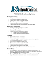
3.12 Interfacing POS Devices
Your DVR can receive POS data from nearly any serial ASCII data source including
registers at the point of sale (POS), ATMs, alarm panel, access control systems,
intelligent safes, weight scales, and other such sources. For the sake of simplicity,
we will refer to all such sources as POS data. Your DVR includes two serial ports
for receiving POS data. If you are using network data capture please refer to Part
II Software for information about the network capture setup.
Direct Serial POS Data Connection
For only one or two POS data sources,
use the direct serial connection
method. Here a pigtail connector is
inserted at the back of the printer
with the printer’s RX and GND
wires paralleled off. A suitable
two-wire data cable connects
this pigtail to another pigtail and
is used at the DVR’s POS port.
Pigtail accessory cables are avail-
able from Image Vault for various
printer styles; sold separately.
Functionally this acts like one
cable as illustrated.
REGISTER
SERIAL
CABLE
PRINTER

16 Image Vault
®
PRO Command
Serial POS Data Hub Connection
If you have three or more POS data sources you will need one or up to two
IVQuad hubs. Each IVQuad hub device offers four data input ports. With two se-
rial ports on the DVR, this means up to 8 serial data sources may be connected to
one DVR. IVQuad data hubs are sold separately.
REGISTER
REGISTER
REGISTER
REGISTER
SERIAL
CABLE
JOURNAL
PRINTER
MULTI-SOURCE
PRINT SERVER
Multi-Device Print Server Serial Data Con-
nection
Though not as common, Image Vault also
supports multi-device serial print server ap-
plications. The wiring is the same as the direct
connection, but through software your DVR
can differentiate source channels.
ON
1 2 3 4 5 6 7 8
ON
1 2 3 4 5 6 7 8
ON
1 2 3 4 5 6 7 8
ON
1 2 3 4 5 6 7 8
+RS485
–RS485
GND
RS232
+RS485
–RS485
GND
RS232
+RS485
–RS485
GND
RS232
+RS485
–RS485
GND
RS232
+RS485
–RS485
GND
RX RS232
TX RS232
TO DVRFROM POS 1FROM POS 2FROM POS 3FROM POS 4
IVQ4 POS DATA HUB
SETUP POS 4 SETUP POS 3 SETUP POS 2 SETUP POS 1
BAUD:
19200
9600
4800
2400
1200
SWITCH #
1
OFF
ON
ON
ON
OFF
2
OFF
ON
ON
OFF
ON
3
ON
ON
OFF
ON
ON
7 DATA BITS
8 DATA BITS
1 STOP BITS
2 STOP BITS
RS232 IN
RS485 IN
SWITCH #
6
OFF
ON
7
ON
OFF
8
ON
OFF
PARITY:
NONE
EVEN
ODD
SWITCH #
IMAGE VAULT
Ph 888-462-4382 Fax 877-296-0038
www.image-vault.com
4
ON
OFF
ON
5
ON
ON
OFF
VIDEO SECURITY
D I G I T A L
PRO-COMMAND DVR
IVQ4
DATA SOURCES
REGISTER
REGISTER
SAFE
ATM
ACCESS
CONTROL
TO DVR
POS PORT

17 Image Vault
®
PRO Command
1 - Short to 4 & 6
2 - Data RX
3 - Open
4 - Short to 1 & 6
5 - Data Ground
6 - Short to 1 & 4
7 - Short to 8
8 - Short to 7
9 - Open
DVR Pigtail Internal Wiring
If you are utilizing the POS Interface feature, ensure that you have obtained the
correct interface connector from Image Vault for the approved device. Warning:
You can harm the DVR by connecting a data device that is not approved by
Image Vault and/or by using an improperly constructed cable. If you manu-
facture your own cable, tap the POS device as follows:
• Data (RX) at the POS printer tap goes to Pin 2 at the DVR.
• POS ground goes to Pin 5 at the DVR.
• At the DVR short Pins 7 and 8 together; short Pins 1, 4 and 6 together;
leave Pins 3 and 9 open.
• Wiring from the data source to journal printer depends on the device
manufacturer.
IV-9 POS Wiring to 9-Pin Serial Printer
This diagram illustrates the proper wiring of the IV-9 pigtail kit used to capture
data at serial printers with DB9 inputs.
DB9P
Pass-thru Connector
DB9F
DVR Connector
DVR PIGTAILHOME RUN WIREIV-9 POS PIGTAIL
Female Side
To Printer
Black (Pin 5)
18 AWG Twisted Pair
White (Pin 3)
OR*
Red (Pin 2)
Black (Pin 5)
Red (Pin 2)
Male Side
To Data Source
To DVR POS
PORT 1 or 2
IV-25 POS Wiring to 25-Pin Serial Printer
This diagram illustrates the proper wiring of the IV-25 pigtail kit used to capture
data at serial printers with DB25 inputs.
DB25P
Pass-thru Connector
DB9F
DVR Connector
DVR PIGTAILHOME RUN WIREIV-25 POS PIGTAIL
Male Side
To Printer
Black (Pin 5)
18 AWG Twisted Pair
White (Pin 3)
OR*
Red (Pin 2)
Black (Pin 5)
Red (Pin 2)
Female Side
To Data Source
To DVR POS
PORT 1 or 2

18 Image Vault
®
PRO Command
IV-G POS Wiring to Gilbarco
This diagram illustrates the proper wiring of the IV-G pigtail kit used to capture
data from Gilbarco register systems.
IV-R POS Wiring to Ruby Verifone
This diagram illustrates the proper wiring of the IV-R pigtail kit used to capture
data from Ruby Verifone register systems using RJ45-style printer cables.
Plug into the “JNL PNTR”
Port on the G-Site Register
DB9F
DVR Connector
DVR PIGTAILHOME RUN WIREIV-G POS PIGTAIL
18 AWG Twisted Pair
Orange
(Pin 2)
Black (Pin 3)
Black (Pin 5)
Red (Pin 2)
To DVR POS
PORT 1 or 2
DB9F
DVR Connector
DVR PIGTAILHOME RUN WIRE
IV-R POS PIGTAIL
18 AWG Twisted Pair
Black (Pin 5)
Black (Pin 6)
Male Side to
Printer or Terminal
Female Side to
Existing Printer Cable
Red (Pin 2)
Red (Pin 1)
To DVR POS
PORT 1 or 2

19 Image Vault
®
PRO Command
POS Quad Data Hub Wiring
The primary function of the POS Quad Data Hub is to bring up to four serial data
sources into one serial stream. Specify the accessory kit desired when ordering
data hubs. Any of the accessory kit hardware can be bundled with the Quad hub.
Such kits include four accessory pigtails plus one RS232 null modem cable. This
diagram illustrates (generically) how one POS Data Hub is wired.
ON
12345678
ON
12345678
ON
12345678
ON
12345678
+RS485
–RS485
GND
RS232
+RS485
–RS485
GND
RS232
+RS485
–RS485
GND
RS232
+RS485
–RS485
GND
RS232
+RS485
–RS485
GND
RX RS232
TX RS232
TO DVRFROM POS 1FROM POS 2FROM POS 3FROM POS 4
IVQ4 POS DATA HUB
SETUP POS 4 SETUP POS 3 SETUP POS 2 SETUP POS 1
BAUD:
19200
9600
4800
2400
1200
SWITCH #
1
OFF
ON
ON
ON
OFF
2
OFF
ON
ON
OFF
ON
3
ON
ON
OFF
ON
ON
7 DATA BITS
8 DATA BITS
1 STOP BITS
2 STOP BITS
RS232 IN
RS485 IN
SWITCH #
6
OFF
ON
7
ON
OFF
8
ON
OFF
PARITY:
NONE
EVEN
ODD
SWITCH #
IMAGE VAULT
Ph 888-462-4382 Fax 877-296-0038
www.image-vault.com
4
ON
OFF
ON
5
ON
ON
OFF
VIDEO SECURITY
D I G I T A L
Black
Black
Red
Red
DVR PIGTAIL
IVQ4 WIRING WITH ACCESSORY KIT
IV-9/IV-25/IV-G/IV-R POS PIGTAILS
AND HOME RUN WIRES

20 Image Vault
®
PRO Command
Network POS Data
Capturing POS data from a network print server does not require any additional
cables. The DVR must be connected to the same local network as the POS data
source.Coordinatedsoftwarecongurationofthenetworkprintserver(s)and
DVR is required. In software setup you have the options of receiving POS data
directly from one network POS source, multiple sources, or from the print server.
DATA SOURCES
REGISTER
REGISTER
REGISTER
REGISTER
ETHERNET CABLE
NETWORK
PRINTER
ETHERNET
HUB
TPC/IP NETWORK
PRINT SERVER
/