Heath Zenith HZ-4114-HB Installation guide
- Category
- Work lights
- Type
- Installation guide

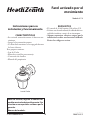
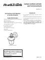
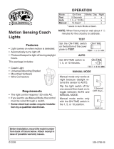
Motion-activated
Coach Light
Coach Light
FEATURES
• Automatically comes on when motion is de-
tected.
• Automatically turns light o.
• Photocell keeps the light o during daylight
hours.
is package includes:
• Coach Light
• Mounting Bracket and Screws
• Wire Connectors
• Owner’s Manual
REQUIREMENTS
• e light control requires 120 volts AC.
• If you want to use Manual Mode, the control
must be wired through a switch.
• Some electrical codes require installation by
a qualied electrician. Please check the codes
in your area.
Model 4114
Before installation, record the model num-
ber listed inside the xture. Attach receipt
in case of possible warranty issues.
Model Number:
Installation and
Operating Instructions
© 2015 HeathCo LLC 206873-02A

2
206873-02
WARNING: Turn power o at circuit
breaker or fuse. Place tape over circuit
breaker switch and verify power is o at
the xture.
Wire Path Ground Screw
Mounting
Plate
INSTALLATION
Decorative Nut
Mounting Screw
Bracket
Mounting
Screw
Mounting
Plate
Junction
Box
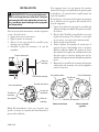
Note: We recommend having an assistant help hold
the lantern assembly during the wiring process.
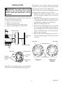
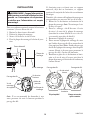
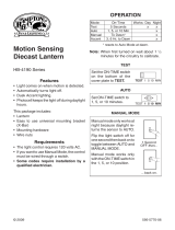
is xture comes with a universal mounting
bracket. It is pre-assembled on the xture to t
the majority of junction box applications.
However, if the slots on the mounting plate do not
line up with the junction box screw holes:
1. Remove the xture mounting screws from
the mounting plate. Note: Do not remove the
ground screw.
2. Attach ground wire “pigtail” to ground screw on
mounting plate (See Recommended Ground-
ing Method for additional information).
3. Flip the mounting plate over.
4. Rotate the mounting plate so the wire path
is on the upper right. Note: e wire path on
the mounting plate must be located as shown
below to allow the wires on the back of the
xture to pass through.
5. Reinstall the xture mounting screws and at-
tach the mounting plate to the junction box
as shown.
Wire Path Wire Path
Fixture Screws
Ground Screw
As Shipped Flipped and
Rotated
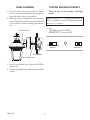
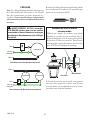
For best performance, mount the xture about 6
feet (1.8 m) above the ground.
1. Remove two decorative nuts.
2. Remove mounting plate.
3. Tighten mounting screws nger tight.
4. Attach mounting plate to junction box.

3
206873-02
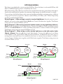
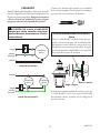
Black to black
White to white
Recommended Grounding Method
Use a green ground “pigtail” (not provided) and
twist one end together with the bare xture wire
and the box ground wire. Secure with a wire
connector. Secure the other end of the “pigtail”
with the GND screw on the mounting plate.
WIRING
Note: All wiring must be run in accordance with
the National Electrical Code through conduit
or another acceptable means. Contact a quali-
ed electrician if there is any question as to the
suitability of the system.
CAUTION: DO NOT connect the RED wire
unless you want to control other lights from
the motion sensor (see Optional Wiring).
Connect the xture wires to the wires in the junc-
tion box. Twist the wires together and secure with
wire connectors.
If you have metal junction box, you may not need
the green “pigtail”. If you are unsure about the
grounding method, consult your local building
code.
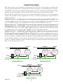
One Motion Light
Two Motion Lights
Black
White
Green
or Bare
Light
Fixture
Black
White
Green
or Bare
Light
Fixture
Light
Fixture

4
206873-02
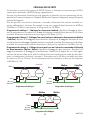
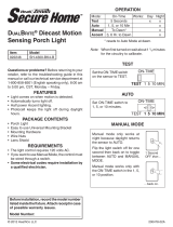
OPTIONAL WIRING
is xture is provided with a sensor rated for 500 Watts. Since the xture is only rated 60 Watts, 440
Watts of additional lighting may be controlled by this sensor.
When determining what a xture is rated for, do not simply look at the rating on the lamp in the xture.
Look at the marking which species the maximum lamp wattage for which the xture is suitable.
Once you have selected the xtures to be connected and determined their maximum ratings, add these
ratings up. For instance, if you have 3 xtures rated 60 Watts, 150 Watts, and 75 Watts respectively,
you have a total load of 215 Watts.
Wiring Diagram 1 – When wiring to control a standard light xture: Strip the motion sensor’s
red wire and connect to the standard light’s black wire. Connect all white wires together. Total xture
ratings must not exceed 500 Watts (4.1 A).
Wiring Diagram 2 – When wiring to control another motion sensing light xture (Master /
Slave): Strip the red wire in both light xtures. Connect the red wire of the controlling (master)
xture to the red and black wires of the controlled (slave) xture. Connect all white wires together.
Total xture ratings must not exceed 500 Watts (4.1 A).
Wiring Diagram 3 – When wiring so either motion light turns on the both motion lights
(Master / Master): Strip the red wire in both light xtures. Connect the red wire of one xture
to the red wire of the second xture. Note: In most installations, an additional wire (same gauge as
existing house wire) will have to be installed in the house to connect the two xtures as master /
master. Connect all white wires together and all black wires together. Total xture ratings must not
exceed 500 Watts (4.1 A).
Black
White
Green
or Bare
Light
Fixture
Light
Fixture
(Standard) Master Slave
Black
White
Green
or Bare
Light
Fixture
Light
Fixture
Red
Red
Wiring Diagram 1 Wiring Diagram 2
Wiring Diagram 3
Master
Black
White
Red
Green
or Bare
Master
Light
Fixture
Light
Fixture

5
206873-02
Junction Box
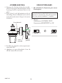
FINAL ASSEMBLY
1. Push the wires into the junction box. Make
sure the wires from the xture go through the
wire path and no wires get pinched.
2.
Slide the xture assembly onto the mounting
screws. Tighten decorative nuts removed in step
1 of Installation section securely against xture
base.
Mounting Screw
Decorative Nut
3. Install one medium base light bulb (60 Watt
maximum).
4. Caulk around xture base with silicone weather
sealant.
TESTING AND ADJUSTMENTS
1. Turn on the circuit breaker and light
switch.
Note: Sensor has a 1
1
/
2
minute warm up period
before it will detect motion. When rst turned
on wait 1
1
/
2
minutes.
2. Set:
ON-TIME switch to TEST
SENSITIVITY switch to “M”
TEST 1 5 10 MIN
ON-TIME
LO - M - HI
SENSITIVITY

6
206873-02
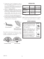
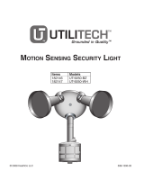
30 ft.
(9.1 m)
6 ft.
(1.8 m)
150°
3.
Walk through the coverage area noting where
you are when the lights turn on. In TEST mode,
light will stay on for 5 seconds after sensing
motion and then turn o.
4.
Adjust the SENSITIVITY to increase or
decrease the range as needed. Too much sen-
sitivity may cause false triggering due to heat
sources in the coverage area (see
Adjustment of
Coverage Area or Troubleshooting
section).
5. Set the amount of ON-TIME you want the
light to stay on after motion is detected (1, 5,
or 10 minutes).
Maximum
Maximum Range Coverage Angle*
(Top View)
Note: When rst turned on wait about 1
1
/
2
minutes
for the circuitry to calibrate.
* resets to Auto Mode at dawn.
Least Sensitive Most Sensitive
e sensor is less sensitive to motion directly
towards it and more sensitive to motion across
coverage area.
Sensor
Motion Motion
OPERATION
Mode: On-Time Works: Day Night
Test
5 Seconds x x
Auto
1, 5, or 10
Minutes
x
Manual
To Dawn* x
... back on.
1 Second
OFF then...
Manual mode only works at
night because daylight returns
the sensor to AUTO.
Flip the light switch o for one
second then back on to toggle
between AUTO and MANUAL
MODE.
Manual mode works only with
the ON-TIME switch in the 1,
5, or 10 position.
MANUAL MODE

7
206873-02
ADJUSTMENT OF COVERAGE AREA
e sensor on this light xture detects “motion”
by the movement of heat across the coverage
area. However, following are examples of objects
that also produce heat and can cause the sensor
to trigger:
• Pools of Water • Air Conditioners
• Dryer Vents • Animals
• Heating Vents • Automobile Trac
If you suspect that a heat source of this type is
triggering the sensor, reduce the sensitivity.
SPECIFICATIONS
Range .................................................Up to 30 ft. (9.1 m) [varies with surrounding temperature]
Sensing Angle.....................................Up to 150°
Electrical Load ...................................Up to 60 Watt Maximum Incandescent
Bulb Type ...........................................Medium Base, Type “A”, 60 Watt Maximum
Sensor Capacity .................................. Up to 500 Watt (4.1 A) Maximum
Power Requirements ........................... 120 VAC, 60 Hz
Operating Modes ...............................TEST, AUTO, and MANUAL MODE
ON-Timer .......................................... 1, 5, 10 minutes
Test Timer .......................................... 5 Seconds
Manual Mode Timer .......................... Dusk-to-Dawn
is device complies with Part 15 of the FCC Rules. Operation is subject to the following two
conditions: (1) this device may not cause harmful interference, and (2) this device must accept any
interference received, including interference that may cause undesired operation.
CAN ICES-3 (B)/NMB-3(B)
MANUAL MODE
AUTO
TEST
ON-TIME Switch at 1, 5, or 10
minutes
MODE SWITCHING SUMMARY
Flip light switch o for
one second then back
on*
* If you get confused while switching modes, turn
the power o for one minute, then back on. After
the calibration time the control will be in the AUTO
mode.

8
206873-02
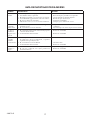
TROUBLESHOOTING GUIDE
SYMPTOM POSSIBLE CAUSE SOLUTION
Lights will not
come on.
1. Light switch is turned o.
2. Lamp is loose or burned out.
3. Fuse is blown or circuit breaker is turned o.
4. Daylight turn-o is in eect.
5. Sensor not detecting movement.
6. Incorrect circuit wiring, if this is a new installation.
1. Turn light switch on.
2. Check lamp and replace if burned out.
3. Replace fuse or turn circuit breaker on.
4. Recheck after dark.
5. Increase sensitivity.
6. Verify wiring is correct.
Lights come on in
daylight.
1. Light control may be installed in a relatively dark
location.
2. Light control is in TEST.
1. e xture is operating normally under these
conditions.
2. Set control switch to 1, 5, or 10 minutes.
Lights come on for
no apparent reason.
1. Light control may be sensing small animals or automobile
trac.
2. Sensitivity is set too high.
1. Reduce sensitivity.
2. Reduce sensitivity.
Lights stay on
continuously.
1. e sensor may be picking up a heat source like an air
vent, dryer vent, or brightly painted, heat-reective
surface.
2. Light control is in Manual Mode.
3. Sensitivity is set too high.
1. Reduce sensitivity.
2. Switch to Auto.
3. Reduce sensitivity.
Lights ash on
and o.
1. Light control is in the TEST mode and warming up.
2. Heat being reected from other objects may be aecting
the sensor.
1. Flashing is normal under these conditions.
2. Reduce sensitivity.

9
206873-02
TWO YEAR LIMITED WARRANTY
is is a “Limited Warranty” which gives you specic legal rights. You may also have other rights which vary from state
to state or province to province.
For a period of two years from the date of purchase, any malfunction caused by factory defective parts or workmanship
will be corrected at no charge to you.
Not Covered - Repair service, adjustment and calibration due to misuse, abuse or negligence, light bulbs, batteries, and
other expendable items are not covered by this warranty. Unauthorized service or modication of the product or of any
furnished component will void this warranty in its entirety. is warranty does not include reimbursement for inconve-
nience, installation, setup time, loss of use, unauthorized service, or return shipping charges.
is warranty covers only HeathCo LLC assembled products and is not extended to other equipment and components
that a customer uses in conjunction with our products.
THIS WARRANTY IS EXPRESSLY IN LIEU OF ALL OTHER WARRANTIES, EXPRESS OR IMPLIED,
INCLUDING ANY WARRANTY, REPRESENTATION OR CONDITION OF MERCHANT ABILITY OR
THAT THE PRODUCTS ARE FIT FOR ANY PARTICULAR PURPOSE OR USE, AND SPECIFICALLY IN
LIEU OF ALL SPECIAL, INDIRECT, INCIDENTAL, OR CONSEQUENTIAL DAMAGES.
REPAIR OR REPLACEMENT SHALL BE THE SOLE REMEDY OF THE CUSTOMER AND THERE SHALL
BE NO LIABILITY ON THE PART OF HEATHCO LLC FOR ANY SPECIAL, INDIRECT, INCIDENTAL,
OR CONSEQUENTIAL DAMAGES, INCLUDING BUT NOT LIMITED TO ANY LOSS OF BUSINESS OR
PROFITS, WHETHER OR NOT FORESEEABLE. Some states or provinces do not allow the exclusion or limitation
of incidental or consequential damages, so the above limitation or exclusion may not apply to you.
Please keep your dated sales receipt, it is required for all warranty requests.
TECHNICAL SERVICE
Please call 1-800-858-8501 (English speaking only) for assistance before
returning product to store.
If you experience a problem, follow this guide. You may also want to visit our Web site at: www.
hzsupport.com. If the problem persists, call* for assistance at 1-800-858-8501 (English speaking
only), 8:00 AM to 5:00 PM CST (M-F). You may also write* to:
HeathCo LLC
P.O. Box 90045
Bowling Green, KY 42102-9045
ATTN: Technical Service
* If contacting Technical Service, please have the following information available: Model Number,
Date of Purchase, and Place of Purchase.
No Service Parts Available for this Product
Please keep your dated sales receipt, it is required for all warranty requests.
HeathCo LLC reserves the right to discontinue products and to change specications at any time
without incurring any obligation to incorporate new features in products previously sold.
Page is loading ...
Page is loading ...
Page is loading ...
Page is loading ...
Page is loading ...
Page is loading ...
Page is loading ...
Page is loading ...
Page is loading ...
Page is loading ...
Page is loading ...
Page is loading ...
Page is loading ...
Page is loading ...
Page is loading ...
Page is loading ...
Page is loading ...
Page is loading ...

28
206873-02
Staple Purchase Receipt Here
Engrape aquí el recibo de compra
Agrafez le reçu d’achat ici
PLEASE KEEP YOUR DATED SALES RECEIPT,
IT IS REQUIRED FOR ALL WARRANTY REQUESTS.
POR FAVOR GUARDE SU RECIBO DE VENTA FECHADO; SE LO
REQUIERE PARA CUALQUIER SOLICITUD DE GARANTÍA.
VEUILLEZ CONSERVER LE REÇU PORTANT LA DATE D'ACHAT;
VOUS EN AUREZ BESOIN POUR TOUTES VOS DEMANDES LIÉES À
LA GARANTIE.
Purchase Information
Información de la compra
Renseignements d’achat
Model #: ________________________ Date of Purchase: _______________________
Nº de modelo / N° de modèle Fecha de compra / Date d’achat
-
 1
1
-
 2
2
-
 3
3
-
 4
4
-
 5
5
-
 6
6
-
 7
7
-
 8
8
-
 9
9
-
 10
10
-
 11
11
-
 12
12
-
 13
13
-
 14
14
-
 15
15
-
 16
16
-
 17
17
-
 18
18
-
 19
19
-
 20
20
-
 21
21
-
 22
22
-
 23
23
-
 24
24
-
 25
25
-
 26
26
-
 27
27
-
 28
28


Heath Zenith HZ-4114-HB Installation guide
- Category
- Work lights
- Type
- Installation guide
Ask a question and I''ll find the answer in the document
Finding information in a document is now easier with AI
in other languages
Related papers
-
Heath Zenith HZ-4265-OR Installation guide
-
Heath Zenith HZ-4151-BR1 User manual
-
Hampton Bay SL-4133-OR User manual
-
Heath Zenith SL-4133-OR - Heath - Shaker Cove Mission Style 150-Degree Motion Sensing Decorative Security Light User manual
-
HeathZenith HZ-4192-BK User manual
-
-
-
-
-
Other documents
-
 Secure Home SH-4192-BK-A User manual
-
 Hampton Bay HBI-4170-PB Installation guide
-
 Hampton Bay HBI-4192-WH Installation guide
-
HeathZenith SL-4110 Motion-activated Coach Light User manual
-
 Secure Home SH-4300-BK-A User guide
-
 Utilitech Motion Sensing Security Light UT-9250-WH Owner's manual
-
 Hampton Bay HB-4305-WH Installation guide
-
Home Decorators Collection HDI-4015-BK Installation guide
-
 World Imports WI30242 Installation guide
-
Zenith WC-6053-WH - Heath - Motion Light Set User manual


