Page is loading ...

Motion Sensing Coach
Lights
Features
• Lightcomesonwhenmotionisdetected.
• Automaticallyturnslightoff.
• Photocellkeepsthelightoffduringdaylight
hours.
Thispackageincludes:
©2009 595-5768-06
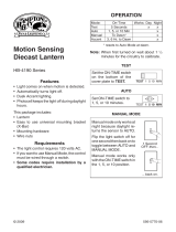
SetON-TIMEswitchto
1,5,or10minutes.
ON-TIME
Set the ON-TIME switch
onthebottomofthecover
platetoTEST.
...backon.
1Second
OFFthen...
Manualmodeonlyworksat
night because daylight re-
turnsthesensortoAUTO.
Flip the light switch off for
onesecondthenbackonto
toggle betweenAUTOand
MANUALMODE.
Manual mode works only
withtheON-TIMEswitchin
the1,5,or10position.
NOTE:Whenrstturnedonwaitabout1
1
/
2
minutesforthecircuitrytocalibrate.
MANUAL MODE
AUTO
*resetstoAutoModeatdawn.
OPERATION
TEST
Mode: On-Time Works: Day Night
Test
5Seconds x x
Auto
1,5,or10Min x
Manual
ToDawn* x
TEST 1 510 MIN
TEST 1 5 10 MIN
ON-TIME
Before installation, record the model number
from back of fixture below. Attach receipt in
case of possible warranty issues.
• CoachLight
• UniversalMountingBracket
• MountingHardware
• WireConnectors
Requirements
• Thelightcontrolrequires120voltsAC.
• IfyouwanttouseManualMode,thecontrol
mustbewiredthroughaswitch.
• Some electrical codes require installa-
tion by a qualified electrician.

2
595-5768-06
MANUAL MODE
AUTO
TEST
ON-TIME Switch at 1, 5,
or 10 minutes
Mode Switching Summary
Flip light switch
off for one second
then back on*
*Ifyougetconfusedwhileswitchingmodes,
turnthepoweroffforoneminute,thenback
on.Afterthecalibrationtimethecontrolwill
beintheAUTOmode.
INSTALLATION
Forbestperformance,mountthextureabout
6feet(1.8m)abovetheground.
WARNING: Turn power off at circuit
breaker or fuse.
1.Removetwonuts.
3.Tightenscrews
ngertight.
2.Remove
MountingPlate.
Thisxturecomeswithauniversalmounting
bracket.Itispre-assembledonthextureto
tthemajorityofjunctionboxapplications.
However,iftheslotsonthemountingplate
donotlineup withthejunctionbox screw
holes:
1. Removethexturemountingscrewsfrom
themountingplate.Note:Donotremove
thegroundscrew.
2. Attach ground wire “pigtail” to ground
screwonmountingplate(SeeRecom-
mended Grounding Methodforadditional
information).
3. Flipthemountingplateover.
4. Rotatethemountingplatesothewirepath
isontheupperright.Note:Thewirepath
onthemountingplatemustbelocated
asshownbelowtoallowthewiresonthe
backofthexturetopassthrough.
5. Reinstallthexturemountingscrewsand
attachthemountingplatetothejunction
boxasshown.
WirePath
4.Attachmounting
platetojunctionbox.
WirePath
GroundScrew
As Shipped Flipped and
Rotated
WirePath
FixtureScrews
GroundScrew

3
595-5768-06
WIRING
One Motion Light
Black
White
Green
orBare
Light
Fixture
CAUTION: DO NOT connect the RED
wire unless you want to control other
lights from the motion sensor.
Note:Allwiringshouldberuninaccordance
with the National Electrical Code through
conduit or another acceptable means.
Contact a qualified electrician if there is
any question as to the suitability of the
system.
❒ Twist the junction box wires and the
xturewirestogetherasshownbelow.
Securewithwireconnectors.Ifyouhave
ametaljunctionbox,youmaynotneed
thegreen“pigtail”.Ifyouareunsureabout
thegroundingmethod,consultyourlocal
buildingcode.
Two Motion Lights
Black
White
Green
orBare
Light
Fixture
Light
Fixture
Connectthexturewirestothewiresinthe
junction box. Twist the wires together and
securewithwireconnectors.
Blacktoblack
Whitetowhite
Recommended Grounding Method
Useagreenground“pigtail”(notprovided)and
twistoneendtogetherwiththebarexturewire
andtheboxgroundwire.Securewith awire
connector.Securetheotherendofthe“pigtail”
withtheGNDscrewonthemountingplate.
OPTIONAL WIRING
Thisxtureisprovidedwithasensorratedfor500Wattstungstenincandescent.Sincethe
xturewattageislessthan500watts,thenadditionallightingloadcanbecontrolled.For
example,ifthextureisratedfor100watts,then400wattsofadditionallightingloadcan
becontrolled.
Whendeterminingwhataxtureisratedfor,donotsimplylookattheratingonthelight
bulbinthexture.Lookatthemarkingwhichspeciesthemaximumbulbwattageforwhich
thextureissuitable.
Onceyouhaveselectedthexturestobeconnectedanddeterminedtheirmaximumrat-
ings,addtheseratingsup.Forinstance,ifyouhave3xturesrated100Watts,150Watts,
and75Wattsrespectively,youhaveatotalloadof325Watts.

4
595-5768-06
Wiring Diagram 1 – When wiring to control a standard light fixture:Stripthemotion
sensor’sredwireandconnecttothestandardlight’sblackwire.Connectallwhitewires
together.Totalxtureratingsmustnotexceed500Watts(4.1A).
Wiring Diagram 2 – When wiring to control another motion sensing light fixture (Mas-
ter / Slave):Striptheredwireinbothlightxtures.Connecttheredwireofthecontrolling
(master)xturetotheredandblackwiresofthecontrolled(slave)xture.Connectallwhite
wirestogether.Totalxtureratingsmustnotexceed500Watts(4.1A).
Wiring Diagram 3 – When wiring so either motion light turns on both motion lights
(Master / Master):Striptheredwireinbothlightxtures.Connecttheredwireofonexture
totheredwireofthesecondxture.Note:Inmostinstallations,anadditionalwire(same
gaugeasexistinghousewire)willhavetobeinstalledinthehousetoconnectthetwox-
turesasmaster/master.Connectallwhitewirestogetherandallblackwirestogether.Total
xtureratingsmustnotexceed500Watts(4.1A).
Black
White
Green
orBare
Light
Fixture
Light
Fixture
(Standard)
Master Slave
Black
White
Green
orBare
Light
Fixture
Light
Fixture
Red
Red
Wiring Diagram 1 Wiring Diagram 2
Wiring Diagram 3
Master Master
Black
White
Red
Green
orBare
Light
Fixture
Light
Fixture

5
595-5768-06
❒ Caulk fixture mounting surface with
siliconeweathersealant.
❒ Installlightbulb.Seexturemarkingsfor
properbulbtypeandwattage.
❒ Ifsoequipped,installthexturetop.Secure
withdecorativescrews.
Slidethextureontothe
mountingscrewsand
tightennuts.
Junction
Box
COMPLETE THE INSTALLATION
❒ Stuffthewiresintothejunctionbox.Make
surethewiresfromthexturegothrough
thewire path,andnowiresgetpinched.

6
595-5768-06
TEST1510MIN
ON-TIME
LO - M - HI
SENSITIVITY
TESTING
❒ Turn on the circuit breaker and light
switch.
Note: Sensorhasa1
1
/
2
minutewarmuppe-
riodbeforeitwilldetectmotion.When
rstturnedonwait1
1
/
2
minutes.
❒ Set SENSITIVITY to mid position and
ON-TIMEtoTESTposition.
❒ Set the SENSITIVITY as needed. Too
muchsensitivitymayincreasefalsetrig-
gering.
❒ SettheamountofTIMEyouwantthelight
tostayonaftermotionisdetected(1,5,
or10minutes).
240°
SensorAiming
AdjustmentAngle
❒ Walkthroughthe coverageareanoting
whereyouarewhenthelightsturnon.
Move the sensor head left or right to
changethecoveragearea.
Note:Graspthesensor
onlyasshownandturn
theentiresensor.Any
other method may
damage the sensor.
Do not force it past
the stops.
Least Sensitive Most Sensitive
30ft.
(9.1m)
Maximum Range Maximum
Coverage Angle
The detector is lesssensitive to motion di-
rectlytowardsitandmoresensitivetoacross
motion.
Sensor
Motion
Motion
6ft.
(1.8m)
Avoid aiming the control at:
•Pools of water or objects that change
temperaturerapidly,suchasheating vents
and air conditioners.Theseheatsources
couldcausefalsetriggering.
•Areaswherepets or trafficmaytrigger
thecontrol.
•Nearby large, light-colored objectsreect-
ingdaylightmaytriggertheshut-offfeature.
Donotpointotherlightsatthesensor.
150°

7
595-5768-06
SPECIFICATIONS
Range........... Upto30ft.(9.1
m)[varieswith
surrounding
temperature]
SensingAngle..... Upto150°
ElectricalLoad..... See rating on xture
formaximumwattage
SensorCapacity ... Upto500Watts(4.1A.)
Maximum Tungsten
Incandescent
SYMPTOM
Light stays on
continuously.
Light flashes
on and off.
POSSIBLE CAUSE
1. Thesensorispointedtoward
aheatsourcelikeanairvent,
dryervent,orbrightly-painted
heat-reectivesurface.(Re-aim
sensor.)
2. LightcontrolisinManualMode.
(Switch to Auto.)
3. Sensitivity is set too high.
(Reduce sensitivity.)
1. Heatbeingreectedfromother
objects may be affecting the
sensor.(Re-aim sensor.)
2. Light control is in the Test
mode and war ming up
(flashing is normal under these
conditions).
POSSIBLE CAUSE
1. Lightswitchisturnedoff.
2. Bulbislooseorburnedout.
3. Fuseisblownorcircuitbreaker
isturnedoff.
4. Daylight turn-off is in effect
(recheck after dark).
5. Incorrectcircuitwiring, ifthis
isanewinstallation.
6. Re-aim the sensor to cover
desiredarea.
1. Lightcontrolmaybeinstalled
inarelativelydarklocation.
2. Light control is in Test. (Set
control switch to an ON-TIME
position.)
1. Light control may be sensing
small animals or automobile
trafc(re-aim sensor).
2. Sensitivity is set too high.
(Reduce sensitivity.)
SYMPTOM
Light will not
come on.
Light comes on
in daylight.
Light comes on
for no apparent
reason.
PowerRequirements120VAC,60Hz
OperatingModes... TEST, AUTO, and
MANUALMODE
TimeDelay ....... 1,5,10minutes
TheHamptonBayLightingCompanyreserves
the right to discontinue products and to
change specications at any time without
incurringanyobligationtoincorporatenew
featuresinproductspreviouslysold.
TROUBLESHOOTING GUIDE
Ifyouexperienceaproblem,followthisguide.
No Service Parts Available for this Product
/