Moxa NPORT 5450AI-M12 User manual

Category
Serial servers
Type
User manual

This manual is also suitable for

NPort 5000AI-M12 Series User Manual
First Edition, June 2012
www.moxa.com/product
© 2012 Moxa Inc. All rights reserved.
Reproduction without permission is prohibited.
NPort 5000AI-M12 Series User Manual
The software described in this manual is furnished under a license agreement and may be used only in accordance with
the terms of that agreement.
Copyright Notice
Copyright ©2012
Moxa Inc.
All rights reserved.
Reproduction without permission is prohibited.
Trademarks
The MOXA logo is a registered trademark of Moxa Inc.
All other trademarks or registered marks in this manual belong to their respective manufacturers.
Disclaimer
Information in this document is subject to change without notice and does not represent a commitment on the part of
Moxa.
Moxa provides this document as is, without warranty of any kind, either expressed or implied, including, but not limited
to, its particular purpose. Moxa reserves the right to make improvements and/or changes to this manual, or to the
products and/or the programs described in this manual, at any time.
Information provided in this manual is intended to be accurate and reliable. However, Moxa assumes no responsibility for
its use, or for any infringements on the rights of third parties that may result from its use.
This product might include unintentional technical or typographical errors. Changes are periodically made to the
information herein to correct such errors, and these changes are incorporated into new editions of the publication.
Technical Support Contact Information
www.moxa.com/support
Moxa Americas
Toll
-free: 1-888-669-2872
Tel:
+1-714-528-6777
Fax:
+1-714-528-6778
Moxa China (Shanghai office)
Toll
-free: 800-820-5036
Tel:
+86-21-5258-9955
Fax:
+86-10-6872-3958
Moxa Europe
Tel:
+49-89-3 70 03 99-0
Fax:
+49-89-3 70 03 99-99
Moxa Asia
-Pacific
Tel:
+886-2-8919-1230
Fax:
+886-2-8919-1231
Table of Contents
1. Introduction ...................................................................................................................................... 1-1
Overview ........................................................................................................................................... 1-2
Package Checklist ............................................................................................................................... 1-2
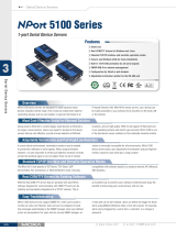
Product Features ................................................................................................................................ 1-2
Product Specifications ......................................................................................................................... 1-2
2. Getting Started.................................................................................................................................. 2-1
NPort 5150AI-M12 Series Appearance ................................................................................................... 2-2
NPort 5250AI-M12 Series Appearance ................................................................................................... 2-2
NPort 5450AI-M12 Series Appearance ................................................................................................... 2-3
Connecting the Hardware..................................................................................................................... 2-3
Wiring Requirements ................................................................................................................... 2-3
Hardware Installation Procedure ........................................................................................................... 2-4
Panel/Wall Mounting .................................................................................................................... 2-4
DIN-Rail Mounting (optional) ........................................................................................................ 2-4
Connecting the Power .................................................................................................................. 2-5
Connecting to the Network ........................................................................................................... 2-5
Connecting to a Serial Device ....................................................................................................... 2-6
LED Indicators ............................................................................................................................ 2-6
3. Initial IP Address Configuration ........................................................................................................ 3-1
Initializing the NPort’s IP Address ......................................................................................................... 3-2
Factory Default IP Address ................................................................................................................... 3-2
NPort Administration Suite ................................................................................................................... 3-2
ARP................................................................................................................................................... 3-2
Telnet Console ................................................................................................................................... 3-3
Serial Console (19200, n, 8, 1) ............................................................................................................. 3-6
4. Choosing the Proper Operation Mode ................................................................................................ 4-1
Overview ........................................................................................................................................... 4-2
Real COM Mode .................................................................................................................................. 4-2
RFC2217 Mode ................................................................................................................................... 4-3
TCP Server Mode ................................................................................................................................ 4-3
TCP Client Mode ................................................................................................................................. 4-3
UDP Mode .......................................................................................................................................... 4-4
Pair Connection Mode .......................................................................................................................... 4-4
Ethernet Modem Mode ......................................................................................................................... 4-4
Reverse Telnet Mode ........................................................................................................................... 4-5
Disabled Mode .................................................................................................................................... 4-5
5. Web Console Configuration ............................................................................................................... 5-1
Opening Your Browser ......................................................................................................................... 5-2
Quick Setup ....................................................................................................................................... 5-3
Export/Import .................................................................................................................................... 5-6
Basic Settings .................................................................................................................................... 5-6
Network Settings ................................................................................................................................ 5-7
LLDP Settings ................................................................................................................................... 5-10
Serial Settings .................................................................................................................................. 5-10
Operating Settings ............................................................................................................................ 5-12
Real COM Mode ......................................................................................................................... 5-13
RFC2217 Mode .......................................................................................................................... 5-16
TCP Server Mode ....................................................................................................................... 5-18
TCP Client Mode ........................................................................................................................ 5-21
UDP Mode ................................................................................................................................ 5-25
Pair Connection Mode ................................................................................................................ 5-27
Ethernet Modem Mode ............................................................................................................... 5-29
Reverse Telnet Mode ................................................................................................................. 5-31
Disabled Mode .......................................................................................................................... 5-32
Accessible IP Settings........................................................................................................................ 5-33
Auto Warning Settings ....................................................................................................................... 5-34
Auto warning: Email and SNMP trap ............................................................................................ 5-34
Event Type ............................................................................................................................... 5-35
Upgrade Firmware ............................................................................................................................ 5-37
Monitor............................................................................................................................................ 5-37
Monitor Line ............................................................................................................................. 5-37
Monitor Async ........................................................................................................................... 5-38
Monitor Async-Settings .............................................................................................................. 5-38
Change Password ............................................................................................................................. 5-39
Load Factory Default ......................................................................................................................... 5-39
Save/Restart .................................................................................................................................... 5-40
6. Configuring NPort Administrator ....................................................................................................... 6-1
Overview ........................................................................................................................................... 6-2
Installing NPort Administrator .............................................................................................................. 6-2
Configuration ..................................................................................................................................... 6-4
Broadcast Search ........................................................................................................................ 6-5
Unlock Password Protection .......................................................................................................... 6-6
Configuring the NPort 5000AI-M12 ................................................................................................ 6-7
Upgrading the Firmware ............................................................................................................... 6-9
Export Configuration .................................................................................................................. 6-10
Import Configuration ................................................................................................................. 6-10
Monitor............................................................................................................................................ 6-11
Port Monitor ..................................................................................................................................... 6-15
COM Mapping ................................................................................................................................... 6-15
On-line COM Mapping ................................................................................................................ 6-16
Off-line COM Mapping ................................................................................................................ 6-19
COM Grouping .................................................................................................................................. 6-20
Creating a COM Group ............................................................................................................... 6-20
Deleting a COM Group................................................................................................................ 6-22
Adding a Port to a COM Group .................................................................................................... 6-24
Removing a Port from a COM Group ............................................................................................ 6-25
Modify Ports in a COM Group ...................................................................................................... 6-27
Changing the COM Number of a COM Group ................................................................................. 6-27
Changing Advanced Settings and Serial Parameters of the COM Group ............................................. 6-29
Changing the Serial Port Specified as Signal Port for the COM Group ............................................... 6-31
IP Address Report ............................................................................................................................. 6-32
7. IP Serial Library ................................................................................................................................ 7-1
Overview ........................................................................................................................................... 7-2
IP Serial Library Function Groups .......................................................................................................... 7-3
Example Program ............................................................................................................................... 7-3
A. Pinouts and Cable Wiring .................................................................................................................. A-1
Pin Assignments and Cable Wiring ........................................................................................................ A-2
Ethernet M12 .............................................................................................................................. A-2
Power M12 ................................................................................................................................. A-2
RS-232/422/485 (male DB9) Pinouts ............................................................................................. A-2
Serial Cable Wiring Diagrams ............................................................................................................... A-3
Female DB9 to Male DB9 .............................................................................................................. A-3
B. Well Known Port Numbers ................................................................................................................ B-1
C. SNMP Agents with MIB II & RS-232 Like Groups .............................................................................. C-1
D. Auto IP Report Protocol .................................................................................................................... D-1
E. Compliance Notice ............................................................................................................................. E-1
1
1. Introduction
Welcome to the NPort 5000AI-M12 Series of industrial serial device servers. There are a total of nine models in
this series and they will be referred to collectively as the “NPort 5000AI-M12 Seriesin this manual.
The nine models in the NPort 5000AI-M12 Series are:
NPort 5150AI-M12 1-port RS-232/422/485 Device Server , 1 x 10/100BaseT(X) with M12
Connector, M12 Power Input, -25 to 55°C
NPort 5150AI-M12-CT 1-port RS-232/422/485 Device Server , 1 x 10/100BaseT(X) with M12
Connector, M12 Power Input, -25 to 55°C, Conformal Coating
NPort 5150AI-M12-T 1-port RS-232/422/485 Device Server , 1 x 10/100BaseT(X) with M12
Connector, M12 Power Input, -40 to 75°C
NPort 5250AI-M12 2-port RS-232/422/485 Device Server , 1 x 10/100BaseT(X) with M12
Connector, M12 Power Input, -25 to 55°C
NPort 5250AI-M12-CT 2-port RS-232/422/485 Device Server , 1 x 10/100BaseT(X) with M12
Connector, M12 Power Input, -25 to 55°C, Conformal Coating
NPort 5250AI-M12-T 2-port RS-232/422/485 Device Server , 1 x 10/100BaseT(X) with M12
Connector, M12 Power Input, -40 to 75°C
NPort 5450AI-M12 4-port RS-232/422/485 Device Server , 1 x 10/100BaseT(X) with M12
Connector, M12 Power Input, -25 to 55°C
NPort 5450AI-M12-CT 4-port RS-232/422/485 Device Server , 1 x 10/100BaseT(X) with M12
Connector, M12 Power Input, -25 to 55°C, Conformal Coating
NPort 5450AI-M12-T 4-port RS-232/422/485 Device Server , 1 x 10/100BaseT(X) with M12
Connector, M12 Power Input, -40 to 75°C
The following topics are covered in this chapter:
Overview
Package Checklist
Product Features
Product Specifications
NPort 5000AI-M12 Series Introduction
1-2
Overview
NPort 5000AI-M12 device server is designed to make serial devices network-ready in an instant and is
compliant with EN 50155 and EN 50121-4 standards, allowing them to perform reliably in rolling stock and
wayside applications where high level vibration is present. Use the NPort 5000AI-M12 device servers to give
your PC software direct access to serial devices from anywhere on the network.
Package Checklist
Before installing the NPort 5000AI-M12 series device servers, verify that the package contains the following
items:
Standard Accessories
1 NPort 5000AI-M12 serial device server
Documentation and Software CD
Quick Installation Guide (printed)
Warranty Card
Optional Accessories
DR-45-24 45W/2A DIN-Rail 24 VDC Power Supply with universal 85 to 264 VAC input
DR-75-24 75W/3.2A DIN-Rail 24 VDC Power Supply with universal 85 to 264 VAC input
DR-120-24 120W/5A DIN-Rail 24 VDC Power Supply with 88 to 132 VAC/176 to 264 VAC input
DK-TN-5308 DIN-Rail kit
NOTE: Notify your sales representative if any of the above items is missing or damaged.
Product Features
The NPort 5000AI-M12 Series are the world’s first EN 50155 compliant device servers and includes:
Speedy 3-step web-based configuration
COM port grouping and UDP multicast applications
Real COM/TTY drivers for Windows and Linux
Standard TCP/IP interface and versatile TCP and UDP operation modes
Compliant with EN 50121-4 and essential sections of EN 50155
M12 connector and IP40 metal housing
2 KV isolation for serial signals
Product Specifications
Ethernet Interface
Number of Ports: 1
Speed:
10/100 Mbps, auto MDI/MDIX
Connector:
M12
Serial Interface
Number of Ports:
1/2/4
Serial Standards:
RS-232/422/485
Connector:
DB9 male
Serial Line Protection:
15 KV ESD protection for all signals
RS
-485 Data Direction Control: ADDC® (automatic data direction control)
Serial Communication Parameters
Data Bits:
5, 6, 7, 8
NPort 5000AI-M12 Series Introduction
1-3
Stop Bits:
1, 1.5, 2
Parity:
None, Even, Odd, Space, Mark
Flow Control:
RTS/CTS and DTR/DSR (RS-232 only), XON/XOFF
Baudrate:
50 to 921.6 Kbps
Serial Signals
RS
-232: TxD, RxD, RTS, CTS, DTR, DSR, DCD, GND
RS-422: Tx+, Tx-, Rx+, Rx-, GND
RS
-485-4w: Tx+, Tx-, Rx+, Rx-, GND
RS
-485-2w: Data+, Data-, GND
Software
Network Protocols:
ICMP, IP, TCP, UDP, DHCP, BOOTP, Telnet, DNS, SNMP V1, HTTP, SMTP, IGMP V1/2,
LLDP
Configuration Options:
Web Console (with new Quick Setup), Telnet Console, Windows Utility
Windows Real COM Drivers:
Windows 98/ME/NT/2000, Windows XP/2003/Vista/2008/7 x86/x64
Fixed TTY Drivers:
SCO Unix, SCO OpenServer, UnixWare 7, UnixWare 2.1, SVR 4.2, QNX 4.25, QNX 6,
Solaris 10, FreeBSD, AIX 5.x, HP
-UX 11i, Mac 10.3
Linux Real TTY Drivers:
Linux kernel 2.4.x, 2.6.x, 3.x
Physical Characteristics
Housing:
Metal, IP40 protection
Weight:
0.56 kg (1.23 lb)
Dimensions:
80 x 216.6 x 52.9 mm (3.15 x 8.53 x 2.08 in)
Environmental Limits
Operating Temperature:
Standard Models:
-25 to 55°C (-13 to 131°F)
Wi
de Temp. Models: -40 to 75°C (-40 to 167°F) EN 50155 Compliant
Ambient Relative
Humidity: 5 to 95% (non-condensing)
Storage Temperature:
-40 to 85°C (-40 to 185°F) EN 50155 Compliant
Power Requirements
Input Voltage:
12 to 48 VDC
Power Consumption:
NPort
5150AI-M12: 310mA @12V
NPort 5150AI
-M12-CT: 310mA @12V
NPort 5150AI
-M12-T: 310mA @12V
NPort 5250AI
-M12: 360mA @12V
NPort 5250AI
-M12-CT: 360mA @12V
NPort 5250AI
-M12-T: 360mA @12V
NPort 5450AI
-M12: 440mA @12V
NPort 5450AI
-M12-CT: 440mA @12V
NPort
5450AI-M12-T: 440mA @12V
Connector: M12
For railway rolling stock applications, the device must use a galvanically isolated power supply that
is compliant with the EN 50155 standard.
Standards and Certifications
EMI
: EN 55022 Class A, FCC Part 15 Subpart B Class A
Safety:
UL 60950-1, EN 60950-1
EMC:
EC, FCC
EMS:
EN 55024
Rail Traffic: EN 50155, EN 50121
-4
Reliability
Alert Tools:
Built-in buzzer and RTC
Automatic Reboot Trigger: Built-in WDT (watchdog timer)
NPort 5000AI-M12 Series Introduction
1-4
MTBF (mean time
between failures):
NPort 5150AI
-M12: 789,341 hrs
NPort 5250AI
-M12: 639,622 hrs
NPort 5450AI
-M12: 467,777 hrs
Warranty
Warranty Period:
5 years
Details: See www.moxa.com/warranty
2
2. Getting Started
In this chapter, we give instructions on installing NPort 5000AI-M12 device servers. Software installation is
covered in subsequent chapters.
The following topics are covered in this chapter:
NPort 5150AI-M12 Series Appearance
NPort 5250AI-M12 Series Appearance
NPort 5450AI-M12 Series Appearance
Connecting the Hardware
Wiring Requirements
Hardware Installation Procedure
Panel/Wall Mounting
DIN-Rail Mounting (optional)
Connecting the Power
Connecting to the Network
Connecting to a Serial Device
LED Indicators
NPort 5000AI-M12 Series Getting Started
2-2
NPort 5150AI-M12 Series Appearance
NPort 5250AI-M12 Series Appearance
NPort 5000AI-M12 Series Getting Started
2-3
NPort 5450AI-M12 Series Appearance
Connecting the Hardware
This section describes how to connect NPort 5000AI-M12 to serial devices for first time testing purposes. We
cover Wiring Requirements, Connecting the Power, Connecting to the Network, Connecting to a
Serial Device, and LED Indicators.
Wiring Requirements
ATTENTION
Safety First!
Be sure to disconnect the po
wer cord before installing and/or wiring your NPort 5000AI-M12 Series.
Wiring Caution!
Calculate the maximum possible current in each power wire and common wire. Observe all electrical codes
dictating the maximum current allowable for each wire size.
If the current goes above the maximum ratings, the wiring could overheat, causing serious damage to your
equipment.
Temperature Caution!
Please take care when handling NPort
5000AI-M12. When plugged in, NPort 5000AI-M12’s internal
components generate heat, and consequently the casing may feel hot to the touch. When installed with other
components, make sure that there is at least 2 cm clearance on all sides of NPort
5000AI-M12
in order to allow
proper heat dissipation.
NPort 5000AI-M12 Series Getting Started
2-4
You should observe the following:
Use separate paths to route wiring for power and devices. If power wiring and device wiring paths must
cross, make sure the wires are perpendicular at the intersection point.
NOTE: Do not run signal or communication wiring and power wiring in the same wire conduit. To
avoid interference, wires with different signal characteristics should be routed separately.
You can use the type of signal transmitted through a wire to determine which wires should be kept separate.
The rule of thumb is that wiring that shares similar electrical characteristics can be bundled together.
Keep input wiring and output wiring separate.
Where necessary, it is strongly advised that you label wiring to all devices in the system.
Hardware Installation Procedure
Panel/Wall Mounting
Mounting the NPort 5000AI-M12 on the wall requires 3 screws. Please use the 3 screws included.
STEP 1: Prepare the 3 screw holes on the wall according to the positions of the 3 screw holes on the device server shown on the mounting
dimension diagram.
STEP 2: Use one screw to go through the top-middle screw hole on the device server and screw it into the wall.
STEP 3: Screw in the remaining 2 screws through the bottom-left and bottom-right holes on the device server to the wall.
NOTE
Please use the screws (
M3 x 40 mm) included.
DIN-Rail Mounting (optional)
With the optional DIN-Rail mounting kit DK-TN-5308 (must be purchased separately), you can mount the NPort 5000AI-M12 on a 35mm
DIN-Rail.
STEP 1: Fix the DIN-Rail attachment plate onto the rear panel of the device server as shown in the figure at the right.
NPort 5000AI-M12 Series Getting Started
2-5
STEP 2: Position the NPort 5000AI-M12 on the DIN-Rail, tilting to hook clamps over the top edge of the rail.
STEP 3:
Swing the device server down fully onto the DIN-Rail until both clamps completely latch.
Connecting the Power
Connect the power line with the NPort 5000AI-M12s M12 connector. If the power is properly supplied, the
ReadyLED will show a solid red color until the system is ready, at which time the “Ready” LED will change to
a green color.
Connecting to the Network
Connect one end of the Ethernet cable to the NPort 5000AI-M12’s 10/100M Ethernet port and the other end of
the cable to the Ethernet network. If the cable is properly connected, the NPort 5000AI-M12 will indicate a valid
connection to the Ethernet in the following ways:
The Ethernet LED maintains a solid green color when connected to a 100 Mbps Ethernet network.
The Ethernet LED maintains a solid orange color when connected to a 10 Mbps Ethernet network.
The Ethernet LED will flash when Ethernet packets are being transmitted or received.
NPort 5000AI-M12 Series Getting Started
2-6
Connecting to a Serial Device
Connect the serial data cable between NPort 5000AI-M12 and the serial device. Serial data cables are optional
accessories for NPort.
LED Indicators
The top panels of all NPort 5000AI-M12 have four LED indicators, as described in the following table.
Name Color Function
PWR green Power is being supplied to the power input.
Ready
red
Steady on: Power is on and NPort is booting up.
Blinking: Indicates an IP conflict, or DHCP/BOOTP server did not respond properly.
green
Steady on: Power is on and NPort is functioning normally.
Blinking: The NPort has been located by NPort Administrator’s Location function.
off Power is off, or a power error condition exists.
10M,
100M
orange 10 Mbps Ethernet connection.
green 100 Mbps Ethernet connection.
off Ethernet cable is disconnected.
P1, P2,
P3, P4
orange Serial port is receiving data.
green Serial port is transmitting data.
off No data is being transmitted or received through the serial port.
3
3. Initial IP Address Configuration
When setting up your NPort 5000AI-M12 for the first time, the first thing you should do is configure the IP
address. This chapter introduces the methods that can be used to configure the device server’s IP address.
Select one of the initial IP Address configuration methods to configure NPort 5000AI-M12’s IP
Address. For more details about network settings, see the Network Settings section from Chapter 5, Web
Console Configuration.
The following topics are covered in this chapter:
Initializing the NPorts IP Address
Factory Default IP Address
NPort Administration Suite
ARP
Telnet Console
Serial Console (19200, n, 8, 1)
NPort 5000AI-M12 Series Initial IP Address Configuration
3-2
Initializing the NPort’s IP Address
1. Determine whether your NPort 5000AI-M12 needs to use a Static IP or Dynamic IP (either DHCP or BOOTP
application).
2. If the NPort 5000AI-M12 is used in a Static IP environment, you can use NPort Administration Suite,
ARP, Web Console, Telnet Console, or Serial Console to configure the new IP address.
3. If the NPort 5000AI-M12 is used in a Dynamic IP environment, you can use NPort 5000AI-M12
Administration Suite, Web Console, Telnet Console, or Serial Console to configure NPort 5000AI-M12 to get
an IP address dynamically with DHCP, DHCP/BOOTP, or BOOTP.
ATTENTION
Consult your network administrator on how to reserve a fixed IP address for your N
Port 5000AI-M12
in the
MAC
-
IP mapping table when using a DHCP Server or BOOTP Server. In most applications, you should assign
a fixed IP address to your NPort
5000AI-M12.
Factory Default IP Address
NPort 5000AI-M12 products are configured with the following default private IP address:
Default IP address: 192.168.127.254
(IP addresses of the form 192.168.xxx.xxx are referred to as private IP addresses, since it is not possible to
directly access a device configured with a private IP address from a public network. For example, you would not
be able to ping such a device from an outside Internet connection. NPort 5000AI-M12 applications that require
sending data over a public network, such as the Internet, require setting up the server with a valid public IP
address, which can be leased from a local ISP.)
NPort Administration Suite
NPort Administration Suite consists of some useful utility programs that are used to configure and manage your
NPort 5000AI-M12.
See Chapter 5 for details on how to install NPort Administration Suite, and how to use this suite of
useful utilities to set up IP addresses and configure your NPort 5000AI-M12 Series serial device
servers.
ARP
You can make use of the ARP (Address Resolution Protocol) command to set up an IP address for your NPort
5000AI-M12. The ARP command tells your computer to associate the NPort 5000AI-M12’s MAC address with
the intended IP address. You must then use Telnet to access the NPort 5000AI-M12, at which point the device
server’s IP address will be reconfigured.
ATTENTION
In order to use this setup method, both your computer and NPort
5000AI-M12 must be
connected to the same
LAN. Or, you may use a cross
-over Ethernet cable to connect the NPort 5000AI-M12 directly to your
computer’s Ethernet card. Before executing the ARP command,
your NPort 5000AI-M12
must be configured
with the factory default IP address
(192.168.127.254), and your computer and the NPort 5000AI-M12
must
be on the same subnet.
NPort 5000AI-M12 Series Initial IP Address Configuration
3-3
Take the following steps to use ARP to configure the IP address:
1. Obtain a valid IP address for your NPort 5000AI-M12 from your network administrator.
2. Obtain the NPort 5000AI-M12s MAC address from the label on its bottom panel.
3. Execute the ‘arp -s’ command from your computer’s MS-DOS prompt by typing:
arp –s 192.168.200.100 00-90-E8-xx-xx-xx
This is where 192.168.200.100 is the new IP address and 00-90-E8-xx-xx-xx is the MAC address for your
NPort 5000AI-M12. (Be sure to use the actual IP address and MAC address for your NPort 5000AI-M12.)
4. Next, execute a special Telnet command by typing:
telnet 192.168.200.100 6000
After issuing this command, a Connect failed message will appear, as shown here. After the NPort reboots,
its IP address should be updated to the new address, and you can reconnect using either Telnet, Web, or
Administrator to check that the update was successful.
Telnet Console
Depending on how your computer and network are configured, you may find it convenient to use network
access to set up your NPort 5000AI-M12’s IP address. This can be done using Telnet.
ATTENTION
Figures in this chapter were generated using
the NPort 5000AI-M12I.
1. From the Windows desktop, click on Start and then select Run.
2. Type telnet 192.168.127.254 (use the correct IP address if different from the default) in the Open text
input box, and then click OK.
3. When the Telnet window opens, if you are prompted to input the Console password, input the password and
then press Enter.
Note that this page will only appear if the NPort is password protected.
NPort 5000AI-M12 Series Initial IP Address Configuration
3-4
4. Type 2 to select Network settings, and then press Enter.
5. Type 1 to select IP address and then press Enter.
6. Use the Backspace key to erase the current IP address, type in the new IP address, and then press
Enter.
NPort 5000AI-M12 Series Initial IP Address Configuration
3-5
7. Press any key to continue
8. Type m and then press Enter to return to the main menu.
9. Type s and then press Enter to Save/Restart the system.
NPort 5000AI-M12 Series Initial IP Address Configuration
3-6
10. Type y and then press Enter to save the new IP address and restart the NPort 5000AI-M12.
Serial Console (19200, n, 8, 1)
You may use the RS-232 console port to set up the IP address for NPort 5000AI-M12. We suggest using PComm
Terminal Emulator, which is available free of charge as part of the PComm Lite program suite, to carry out the
installation procedure, although other similar utilities may also be used.
ATTENTION
The
Serial Console is at serial port 1 of the NPort 5000AI-M12 Series, with RS-232 mode.
Before you start to configure the NPort 5000AI-M12 via serial console, turn off the power and connect the serial
cable from NPort 5000AI-M12 to your computer’s serial port.
1. Connect NPort 5000AI-M12’s serial port 1 directly to your computer’s male RS-232 serial port.
2. From the Windows desktop click on Start Programs PComm Lite Terminal Emulator.
3. When the PComm Terminal Emulator window opens, first click on the Port Manager menu item and select
Open, or simply click on the Open icon.
4. The Property window opens automatically. From the Communication Parameter page, select the
appropriate COM port for the connection, COM1 in this example, and 19200 for Baud Rate, 8 for Data Bits,
None for Parity, and 1 for Stop Bits.
5. From the Property window’s Terminal page, select ANSI or VT100 for Terminal Type and then click OK.
Note: If you select Dumb Terminal as the terminal type, some of the console functionsespecially the
“Monitor” functionmay not work properly.
6. Press the “ ` ” key continuously and then power on the NPort 5000AI-M12.
  • Page 1 1
  • Page 2 2
  • Page 3 3
  • Page 4 4
  • Page 5 5
  • Page 6 6
  • Page 7 7
  • Page 8 8
  • Page 9 9
  • Page 10 10
  • Page 11 11
  • Page 12 12
  • Page 13 13
  • Page 14 14
  • Page 15 15
  • Page 16 16
  • Page 17 17
  • Page 18 18
  • Page 19 19
  • Page 20 20
  • Page 21 21
  • Page 22 22
  • Page 23 23
  • Page 24 24
  • Page 25 25
  • Page 26 26
  • Page 27 27
  • Page 28 28
  • Page 29 29
  • Page 30 30
  • Page 31 31
  • Page 32 32
  • Page 33 33
  • Page 34 34
  • Page 35 35
  • Page 36 36
  • Page 37 37
  • Page 38 38
  • Page 39 39
  • Page 40 40
  • Page 41 41
  • Page 42 42
  • Page 43 43
  • Page 44 44
  • Page 45 45
  • Page 46 46
  • Page 47 47
  • Page 48 48
  • Page 49 49
  • Page 50 50
  • Page 51 51
  • Page 52 52
  • Page 53 53
  • Page 54 54
  • Page 55 55
  • Page 56 56
  • Page 57 57
  • Page 58 58
  • Page 59 59
  • Page 60 60
  • Page 61 61
  • Page 62 62
  • Page 63 63
  • Page 64 64
  • Page 65 65
  • Page 66 66
  • Page 67 67
  • Page 68 68
  • Page 69 69
  • Page 70 70
  • Page 71 71
  • Page 72 72
  • Page 73 73
  • Page 74 74
  • Page 75 75
  • Page 76 76
  • Page 77 77
  • Page 78 78
  • Page 79 79
  • Page 80 80
  • Page 81 81
  • Page 82 82
  • Page 83 83
  • Page 84 84
  • Page 85 85
  • Page 86 86
  • Page 87 87
  • Page 88 88
  • Page 89 89
  • Page 90 90
  • Page 91 91
  • Page 92 92
  • Page 93 93
  • Page 94 94
  • Page 95 95
  • Page 96 96
  • Page 97 97
  • Page 98 98
  • Page 99 99
  • Page 100 100
  • Page 101 101
  • Page 102 102
  • Page 103 103
  • Page 104 104
  • Page 105 105
  • Page 106 106
  • Page 107 107
  • Page 108 108
  • Page 109 109
  • Page 110 110
  • Page 111 111
  • Page 112 112
  • Page 113 113

Moxa NPORT 5450AI-M12 User manual

Category
Serial servers
Type
User manual
This manual is also suitable for

Ask a question and I''ll find the answer in the document

Finding information in a document is now easier with AI