Page is loading ...

NPort 5110 Series User’s Manual
First Edition, December 2004
www.moxa.com/product
Moxa Technologies Co., Ltd.
Tel: +886-2-8919-1230
Fax: +886-2-8919-1231
Web: www.moxa.com
MOXA Technical Support
Worldwide: [email protected]

NPort 5110 User’s Manual
The software described in this manual is furnished under a license agreement and may be used only in
accordance with the terms of that agreement.
Copyright Notice
Copyright 2004 Moxa Technologies Co., Ltd.
All rights reserved.
Reproduction without permission is prohibited.
Trademarks
MOXA is a registered trademark of Moxa Technologies Co., Ltd.
All other trademarks or registered marks in this manual belong to their respective
manufacturers.
Disclaimer
Information in this document is subject to change without notice and does not represent a commitment on the
part of Moxa.
Moxa provides this document “as is,” without warranty of any kind, either expressed or implied, including, but
not limited to, its particular purpose. Moxa reserves the right to make improvements and/or changes to this
manual, or to the products and/or the programs described in this manual, at any time.
Information provided in this manual is intended to be accurate and reliable. However, Moxa Technologies
assumes no responsibility for its use, or for any infringements on the rights of third parties that may result from
its use.
This product might include unintentional technical or typographical errors. Changes are periodically made to the
information herein to correct such errors, and these changes are incorporated into new editions of the
publication.

Table of Contents
Chapter 1 Introduction ..............................................................................................1-1
Overview.......................................................................................................... 1-2
Package Checklist ........................................................................................... 1-2
Product Features ............................................................................................. 1-2
Product Specifications ..................................................................................... 1-3
Chapter 2 Getting Started ......................................................................................... 2-1
Panel Layout.................................................................................................... 2-2
Connecting the Hardware................................................................................ 2-2
Connecting the Power ......................................................................................... 2-2
Connecting to the Network.................................................................................. 2-3
Connecting to a Serial Device............................................................................. 2-3
LED Indicators.................................................................................................... 2-3
Chapter 3 Initial IP Address Configuration.............................................................. 3-1
Initializing NPort 5110’s IP Address ................................................................ 3-2
Factory Default IP Address.............................................................................. 3-2
NPort 5110 Administration Suite ..................................................................... 3-2
ARP ................................................................................................................. 3-2
Telnet Console................................................................................................. 3-3
Serial Console (19200, n, 8, 1)........................................................................ 3-6
Chapter 4 Choosing the Proper Operation Mode ................................................... 4-1
Overview.......................................................................................................... 4-2
TCP Server Mode............................................................................................ 4-2
TCP Client Mode ............................................................................................. 4-2
UDP Mode ....................................................................................................... 4-3
Real COM Mode.............................................................................................. 4-3
Pair Connection Mode ..................................................................................... 4-3
Ethernet Modem Mode .................................................................................... 4-4
Chapter 5 Web Console Configuration .................................................................... 5-1
Opening Your Browser .................................................................................... 5-2
Basic Settings .................................................................................................. 5-4
Network Settings ............................................................................................. 5-5
Serial Settings.................................................................................................. 5-8
Operating Settings......................................................................................... 5-10
Real COM Mode ............................................................................................... 5-10
TCP Server Mode.............................................................................................. 5-12
TCP Client Mode .............................................................................................. 5-15
UDP Mode ........................................................................................................ 5-18
Pair Connection Slave Mode............................................................................. 5-20
Pair Connection Master Mode........................................................................... 5-21
Ethernet Modem................................................................................................ 5-22
Accessible IP Settings ................................................................................... 5-25
Auto Warning Settings................................................................................... 5-26
Auto Warning: E-mail and SNMP Trap............................................................ 5-26
Event Type ........................................................................................................ 5-27
Change Password ......................................................................................... 5-29
Load Factory Defaults ................................................................................... 5-29

Chapter 6 Configuring Windows Administrator...................................................... 6-1
Overview.......................................................................................................... 6-2
Installing Windows Administrator..................................................................... 6-2
Configuration ................................................................................................... 6-6
Broadcast Search................................................................................................. 6-7
Unlock Password Protection ............................................................................. 6-10
Configuring NPort 5110.................................................................................... 6-12
Upgrade Firmware............................................................................................. 6-14
Export/Import.................................................................................................... 6-15
Monitor........................................................................................................... 6-16
Port Monitor ................................................................................................... 6-22
COM Mapping................................................................................................ 6-23
On-line COM Mapping ..................................................................................... 6-23
Off-line COM Mapping .................................................................................... 6-29
IP Location..................................................................................................... 6-30
Chapter 7 IP Serial LIB .............................................................................................. 7-1
Overview.......................................................................................................... 7-2
IP Serial LIB Function Groups ......................................................................... 7-3
Example Program............................................................................................ 7-3
Appendix A Pinouts and Cable Wiring....................................................................... A-1
Port Pinout Diagrams ...................................................................................... A-2
Ethernet Port Pinouts...........................................................................................A-2
Serial Port Pinouts...............................................................................................A-2
Cable Wiring Diagrams.................................................................................... A-3
Ethernet Cables ...................................................................................................A-3
Appendix B Well Known Port Numbers ..................................................................... B-1
Appendix C SNMP Agents with MIB II & RS-232 Like Groups ................................. C-1
Appendix D Auto IP Report Protocol.......................................................................... D-1
Appendix E Service Information..................................................................................E-1
MOXA Internet Services .................................................................................. E-2
Problem Report Form ...................................................................................... E-3
Product Return Procedure............................................................................... E-4

1
1
Chapter 1 Introduction
Welcome to NPort 5110, an advanced, 1-port RS-232 serial device server that makes it easy to
network-enable your devices.
The following topics are covered in this chapter:
! Overview
! Package Checklist
! Product Features
! Product Specifications

NPort 5110 Series User’s Manual Introduction
1-2
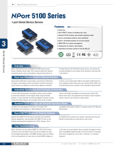
Overview
NPort 5110 serial device server is designed to make your industrial serial devices Internet ready
instantly, and is well-suited for POS security market applications. The compact size of NPort 5110
device server makes them the ideal choice for connecting your RS-232 serial devices, such as card
reader, payment terminal, to an IP-based Ethernet LAN, making it possible for your software to
access serial devices located anywhere on a local LAN, or the Internet.
NPort 5110 serial device server provides TCP Server, TCP Client, UDP Server/Client, Pair
Connection, and Ethernet Modem, ensuring the compatibility of network software that uses a
standard network API (Winsock, BSD Sockets). And thanks to NPort’s Real COM/TTY drivers,
software that works with COM/TTY ports can now work on a TCP/IP network in no time. This
excellent feature preserves your software investment and lets you enjoy the benefits of networking
your serial devices instantly.
NPort 5110 device servers support automatic IP configuration protocols (DHCP, BOOTP) and
manual configuration via the handy web browser console. Both methods ensure quick and
effective installation. And with NPort 5110’s Windows Utility, installation is very straightforward,
since all system parameters can be stored and then copied to other device servers simultaneously.
Package Checklist
NPort 5110 products are shipped with the following items:
Standard Accessories
! 1 NPort 5110 serial device server
! Quick Installation Guide
! NPort Documentation and Software CD-ROM
! Power Adaptor
Optional Accessories
! DK-35A: DIN-Rail Mounting Kit (35mm)
NOTE: Notify your sales representative if any of the above items is missing or damaged.
Product Features
NPort 5110 has the following features:
! Low cost, credit card size
! Makes your serial devices Internet ready
! Easy wall and DIN-Rail mounting
! Real COM/TTY driver for Windows and Linux
! Fixed TTY driver for SCO OpenServer, SCO Unixware 7, SCO Unixware 2.1
! Versatile socket operation modes, including TCP Server, TCP Client, UDP, and Ethernet
Modem modes
! Pair Connection mode for connecting two serial devices over a network without a PC
! Easy-to-use Windows Utility for mass installation
! Auto-detecting 10/100 Mbps Ethernet
! Built-in 15KV ESD protection for all serial signals
! Supports SNMP MIB-II for network management
! Configuration via web/Telnet/serial console
! Configuration utility automatically finds NPort devices on the network

NPort 5110 Series User’s Manual Introduction
1-3
Product Specifications
LAN
Ethernet 10/100 Mbps, RJ45
Protection Built-in 1.5 KV magnetic isolation
NPort 5110 Serial Interface
Interface RS-232
No. of Ports 1
Port Type Male DB9
Signals TxD, RxD, RTS, CTS, DTR, DSR, DCD, GND
Serial Line Protection 15 KV ESD for all signals
Power Line Protection
4 KV Burst (EFT), EN61000-4-4
2 KV Surge, EN61000-4-5
Advanced Built-in Features
Watch Dog Timer
Serial Communication Parameters
Parity None, Even, Odd, Space, Mark
Data Bits 5, 6, 7, 8
Stop Bit 1, 1.5, 2
Flow Control RTS/CTS, XON/XOFF, DTR/DSR
Transmission Speed 110 bps to 230.4 Kbps
Software Features
Protocols ICMP, IP, TCP, UDP, DHCP, BOOTP, Telnet, DNS, SNMP,
HTTP, SMTP
Utilities NPort Administrator for Windows 95/98/ME/NT/2000/XP/2003
Real COM/TTY Drivers Windows 95/98/ME/NT/2000/XP/2003 Real COM driver,
Linux real TTY driver, Unix fixed TTY driver
Configuration Web Browser, Serial/Telnet Console, or Windows Utility
Power Requirements
Power Input 9 to 30 VDC
Power Consumption
Mechanical
Casing Aluminum case (1 mm)
Dimensions (W × H × D) 50 × 80 × 22 mm (1.97 × 3.15 × 0.87 in)
Environmental
Operating Temperature 0 to 55°C (32 to 131°F), 5 to 95%RH
Storage Temperature -20 to 85°C (-4 to 185°F), 5 to 95%RH
Regulatory Approvals
EMC FCC Class A, CE Class A
Safety UL, CUL, TÜV
WARRANTY 5 years

2
2
Chapter 2 Getting Started
This chapter includes information about installing NPort 5110. The following topics are covered:
! Panel Layout
! Connecting the Hardware
" Connecting the Power
" Connecting to the Network
" Connecting to a Serial Device
" LED Indicators

NPort 5110 Series User’s Manual Getting Started
2-2
Panel Layout
NPort 5110
Top Panel View
DIN-Rail
screw hole
Wallmount
screw hole
Ready
Link
Tx/Rx
Serial Device Server
5110
10/100M
Ethernet
RESET
9-30VDC
Port 1 RS-232
Male DB9 serial port
Front Panel View
RJ45 10/100M Ethernet port
Reset button
Power input
Rear Panel View
Stick-on pad
Connecting the Hardware
This section describes how to connect NPort 5110 to serial devices for first time testing purposes.
We cover Connecting to the Network, Connecting to a Serial Device, and LED Indicators.
Connecting the Power
Connect the 9-30 VDC power cord with NPort 5110’s power input. The “Ready” LED will show a
solid red color until the system is ready, at which time the “Ready” LED will change to a green
color.

NPort 5110 Series User’s Manual Getting Started
2-3
Connecting to the Network
Connect one end of the Ethernet cable to NPort 5110’s 10/100M Ethernet port and the other end of
the cable to the Ethernet network. NPort 5110 will indicate a valid connection to the Ethernet in
the following ways:
! The Ethernet LED maintains a solid green color when connected to a 100 Mbps Ethernet
network.
! The Ethernet LED maintains a solid orange color when connected to a 10 Mbps Ethernet
network.
! The Ethernet LED will flash when Ethernet packets are being transmitted or received.
Connecting to a Serial Device
Connect the serial data cable between NPort 5110 and the serial device. NPort 5110’s serial port
uses the RS-232 interface to transmit data. The port uses a standard male DB9 pin assignment.
Refer to Appendix A to see the signal definitions for the port.
LED Indicators
NPort 5110 has 3 LED indicators, as described in the following table.
LED Name LED Color LED Function
Red
Steady on: Power is on and NPort 5110 is booting up.
Blinking: Indicates an IP conflict, or DHCP or BOOTP server
did not respond properly.
Green
Steady on: Power is on and NPort 5110 is functioning normally.
Blinking: The device server has been located by
Administrator’s Location function.
Ready
Off Power is off, or power error condition exists.
Orange 10 Mbps Ethernet connection.
Green 100 Mbps Ethernet connection.
Link
Off
Ethernet cable is disconnected, or has a short.
Orange
Serial port is receiving data.
Green
Serial port is transmitting data.
Tx/Rx
Off
No data is being transmitted or received through the serial port.

3
3
Chapter 3 Initial IP Address Configuration
When setting up your NPort 5110 for the first time, you should first configure the IP address. This
chapter introduces the method to configure the device server’s IP address. For more details about
network settings, see the Network Settings section from Chapter 5, Web Console Configuration.
This chapter includes the following sections:
! Initializing NPort 5110’s IP Address
! Factory Default IP Address
! NPort 5110 Administration Suite
#
recommended configuration method
! ARP
! Telnet Console
! Serial Console (19200, n, 8, 1)

NPort 5110 Series User’s Manual Initial IP Address Configuration
3-2
Initializing NPort 5110’s IP Address
1. Determine whether your NPort 5110 needs to use a Static IP or Dynamic IP (either DHCP or
BOOTP application).
2. If NPort 5110 is used in a Static IP environment, you can use NPort 5110 Administration
Suite, ARP, Web Console, Telnet Console, or Serial Console to configure the new IP address.
3. If NPort 5110 is used in a Dynamic IP environment, you can use NPort 5110 Administration
Suite, Web Console, Telnet Console, or Serial Console to configure NPort 5110 to get an IP
address dynamically with DHCP, DHCP/BOOTP, or BOOTP.
ATTENTION
Consult your network administrator on how to reserve a fixed IP address for your NPort 5110 in
the MAC-IP mapping table when using a DHCP Server or BOOTP Server. In most applications,
you should assign a fixed IP address to your NPort 5110.
Factory Default IP Address
NPort 5110 products are configured with the following default private IP address:
Default IP address: 192.168.127.254
(IP addresses of the form 192.168.xxx.xxx are referred to as private IP addresses, since it is not
possible to directly access a device configured with a private IP address from a public network.
For example, you would not be able to ping such a device from an outside Internet connection.
NPort 5110 applications that require sending data over a public network, such as the Internet,
require setting up the server with a valid public IP address, which can be leased from a local ISP.)
NPort 5110 Administration Suite
NPort 5110 Administration Suite consists of some useful utility programs that are used to
configure and manage your NPort 5110s.
See Chapter 5 for details on how to install NPort 5110 Administration Suite, and how to use
this suite of useful utilities to set up IP addresses and configure your NPort 5110 serial device
servers.
ARP
You can make use of the ARP (Address Resolution Protocol) command to set up an IP address for
your NPort 5110. The ARP command tells your computer to associate the NPort 5110’s MAC
address with the intended IP address. You must then use Telnet to access the NPort 5110, at which
point the device server’s IP address will be reconfigured.
ATTENTION
In order to use the ARP setup method, both your computer and NPort 5110 must be connected to
the same LAN. Or, you may use a cross-over Ethernet cable to connect the NPort 5110 directly
to your computer’s Ethernet card. Your NPort 5110 must be configured with the factory default
IP address—192.168.127.254—before executing the ARP command, as described below.

NPort 5110 Series User’s Manual Initial IP Address Configuration
3-3
Take the following steps to use ARP to configure the IP address:
1. Obtain a valid IP address for your NPort 5110 from your network administrator.
2. Obtain NPort 5110’s MAC address from the label on its bottom panel.
3. Execute the ‘arp -s’ command from your computer’s MS-DOS prompt by typing:
arp –s 192.168.200.100 00-90-E8-xx-xx-xx
This is where 192.168.200.100 is the new IP address and 00-90-E8-xx-xx-xx is the MAC
address for your NPort 5110. You will need to change both numbers, as described above in
items 1 and 2.
4. Next, execute a special Telnet command by typing:
telnet 192.168.200.100 6000
After issuing this command, a Connect failed message will appear, as shown here. After the
NPort 5110 reboots, its IP address should be updated to the new address, and you can
reconnect using either Telnet, Web, or Administrator to check that the update was successful.
Telnet Console
Depending on how your computer and network are configured, you may find it convenient to use
network access to set up your NPort 5110’s IP address. This can be done using Telnet.
1. From the Windows desktop, click on Start and then select Run.
2. Type telnet 192.168.127.254 (use the correct IP address if different from the default) in the
Open text input box, and then click OK.
3. When the Telnet window opens, if you are prompted to input the Console password, input the
password and then press Enter. Note that this page will only appear if the NPort 5110 is
password protected.

NPort 5110 Series User’s Manual Initial IP Address Configuration
3-4
4. Type 2 to select Network settings, and then press Enter.
5. Type 1 to select IP address and then press Enter.

NPort 5110 Series User’s Manual Initial IP Address Configuration
3-5
6. Use the Backspace key to erase the current IP address, type in the new IP address, and then
press Enter.
7. Press any key to continue.

NPort 5110 Series User’s Manual Initial IP Address Configuration
3-6
8. Type m and then press Enter to return to the main menu.
9. Type s and then press Enter to Save/Restart the system.
10. Type y and then press Enter to save the new IP address and restart NPort 5110.
Serial Console (19200, n, 8, 1)
You may use the RS-232 console port to set up the IP address for NPort 5110. We suggest using
PComm Terminal Emulator, which is available free of charge as part of the PComm Lite program
suite (found on the Software CD that comes with the product), to carry out the installation
procedure, although other similar utilities may also be used.
Before you start to configure the NPort 5110 via serial console, turn off the power and connect the
serial cable from NPort 5110 to your computer’s serial port.

NPort 5110 Series User’s Manual Initial IP Address Configuration
3-7
1. Connect NPort 5110’s serial port 1 directly to your computer’s male RS-232 serial port.
2. From the Windows desktop click on Start $ Programs $ PComm Lite $ Terminal
Emulator.
3. When the PComm Terminal Emulator window opens, first click on the Port Manager menu
item and select Open, or simply click on the Open icon.
4. The Property window opens automatically. From the Communication Parameter page,
select the appropriate COM port for the connection, COM1 in this example, and 19200 for
Baud Rate, 8 for Data Bits, None for Parity, and 1 for Stop Bits.
5. From the Property window’s Terminal page, select ANSI or VT100 for Terminal Type and
then click OK. If you select Dumb Terminal as the terminal type, some of the console
functions—especially the “Monitor” function—may not work properly.
6. Press the “ ` ” key continuously and then power on the NPort 5110.
7. NPort 5110 will receive the “ ` ” string continuously and then auto switch from data mode to
console mode.

NPort 5110 Series User’s Manual Initial IP Address Configuration
3-8
8. Input the password when prompted. Note that this page will only appear when the NPort 5110
has been set up for password protection.
9. Start configuring the IP address under Network Settings. Refer to step 4 in the Telnet
Console section for instructions on how to configure the rest of the IP settings.

4
4
Chapter 4 Choosing the Proper Operation Mode
In this section, we describe the various NPort 5110 operation modes. The options include an
operation mode that uses a driver installed on the host computer, and operation modes that rely on
TCP/IP socket programming concepts. After choosing the proper operation mode in this chapter,
refer to Chapter 5 for detailed configuration parameter definitions.
! Overview
! TCP Server Mode
! TCP Client Mode
! UDP Mode
! Real COM Mode
! Pair Connection Mode
! Ethernet Modem Mode

NPort 5110 Series User’s Manual Choosing the Proper Operation Mode
4-2
Overview
NPort 5110 Serial Device Servers are used to network-enable traditional RS-232 devices. A Serial
Device Server is a tiny computer equipped with a CPU, real-time OS, and TCP/IP protocols that
can bi-directionally transfer data between the serial and Ethernet formats. Your computer can
access, manage, and configure remote facilities and equipment over the Internet from anywhere in
the world.
Traditional SCADA and data collection systems rely on serial ports (RS-232) to collect data from
various kinds of instruments. Since NPort 5110 Serial Device Servers network-enable instruments
equipped with an RS-232 communication port, your SCADA and data collection system will be
able to access all instruments connected to a standard TCP/IP network, regardless of whether the
devices are used locally or at a remote site.
NPort 5110 is an external IP-based network device that allows you to expand the number of serial
ports for a host computer on demand. As long as your host computer supports the TCP/IP protocol,
you won’t be limited by the host computer’s bus limitation (such as ISA or PCI), or lack of drivers
for various operating systems.
In addition to providing socket access, NPort 5110 also comes with a Real COM/TTY driver that
transmits all serial signals intact. This means that your existing COM/TTY-based software can be
preserved, without needing to invest in additional software.
Three different Socket Modes are available: TCP Server, TCP Client, and UDP Server/Client. The
main difference between the TCP and UDP protocols is that TCP guarantees delivery of data by
requiring the recipient to send an acknowledgement to the sender. UDP does not require this type
of verification, making it possible to offer speedier delivery. UDP also allows data to be unicast or
multicast to only one IP or to different groups of IP addresses.
TCP Server Mode
In TCP Server mode, NPort 5110 is configured with a unique IP:Port address on a TCP/IP network.
NPort 5110 waits passively to be contacted by the host computer, allowing the host computer to
establish a connection with and get data from the serial device. This operation mode also supports
up to 4 simultaneous connections, so that multiple hosts can collect data from the same serial
device—at the same time.
As illustrated in the figure, data transmission proceeds as follows:
1. The host requests a connection from the NPort 5110 configured for TCP Server Mode.
2. Once the connection is established, data can be transmitted in both directions—from the host
to the NPort 5110, and from the NPort 5110 to the host.
TCP Client Mode
In TCP Client mode, NPort 5110 can actively establish a TCP connection to a pre-defined host
computer when serial data arrives.
After the data has been transferred, NPort 5110 can automatically disconnect from the host
computer by using the TCP alive check time or Inactivity time settings. Refer to Chapter 5 for
more details.
Data transmission proceeds as follows:
1. The NPort 5110 configured for TCP Client Mode requests a connection from the host.
2. Once the connection is established, data can be transmitted in both directions—from the host
to the NPort 5110, and from the NPort 5110 to the host.
/