Page is loading ...

P/N 30-3550
2002-2007 Suzuki GSXR1300 Hayabusa
6 Speed
Plug & Play Adapter Harness
AEM Performance Electronics
AEM Performance Electronics, 2205 126th Street Unit A, Hawthorne, CA 90250
Phone: (310) 484-2322 Fax: (310) 484-0152
http://www.aemelectronics.com
Instruction Part Number: 10-3550
Document Build 8/24/2015
Instruction
Manual
STOP!
THIS PRODUCT HAS LEGAL RESTRICTIONS.
READ THIS BEFORE INSTALLING/USING!
THIS PRODUCT MAY BE USED SOLELY ON VEHICLES USED IN SANCTIONED COMPETITION WHICH MAY NEVER BE USED UPON A
PUBLIC ROAD OR HIGHWAY, UNLESS PERMITTED BY SPECIFIC REGULATORY EXEMPTION. (VISIT THE “EMISSIONS” PAGE AT HTTP://
WWW.SEMASAN.COM/EMISSIONS FOR STATE BY STATE DETAILS.)
IT IS THE RESPONSIBILITY OF THE INSTALLER AND/OR USER OF THIS PRODUCT TO ENSURE THAT IT IS USED IN COMPLIANCE WITH
ALL APPLICABLE LAWS AND REGULATIONS. IF THIS PRODUCT WAS PURCHASED IN ERROR, DO NOT INSTALL AND/OR USE IT. THE
PURCHASER MUST ARRANGE TO RETURN THE PRODUCT FOR A FULL REFUND.
THIS POLICY ONLY APPLIES TO INSTALLERS AND/OR USERS WHO ARE LOCATED IN THE UNITED STATES; HOWEVER CUSTOMERS
WHO RESIDE IN OTHER COUNTRIES SHOULD ACT IN ACCORDANCE WITH THEIR LOCAL LAWS AND REGULATIONS.
WARNING: This installation is not for the tuning novice! Use this system with EXTREME caution! The AEM
Infinity Programmable EMS allows for total flexibility in engine tuning. Misuse or improper tuning of this
product can destroy your engine! If you are not well versed in engine dynamics and the tuning of engine
management systems DO NOT attempt the installation. Refer the installation to an AEM-trained tuning
shop or call 800-423-0046 for technical assistance.
NOTE: All supplied AEM calibrations, Wizards and other tuning information are offered as potential
starting points only. IT IS THE RESPONSIBILITY OF THE ENGINE TUNER TO ULTIMATELY CONFIRM IF THE
CALIBRATION IS SAFE FOR ITS INTENDED USE. AEM holds no responsibility for any engine damage that
results from the misuse or mistuning of this product!

2
© 2015 AEM Performance Electronics
P/N 30-3550
OVERVIEW
The 30-3550 AEM Infinity Adapter Kit was designed for the 2002–2007 Suzuki GSXR1300 Hayabusa.
This is a true standalone system that eliminates the use of the factory ECU. The use of this adapter
makes the kit “plug and play” so no cutting or splicing wires is necessary. The base configuration files
available for the Infinity EMS are starting points only and will need to be modified for every specific
application. Included in these instructions are descriptions of important differences between using the
factory Suzuki ECU and using the AEM Infinity ECU.
The available AEM Infinity EMS part numbers for this adapter kit are:
30-7106 INFINITY-6
GETTING STARTED
Refer to the 10-7106 for EMS 30-7106 Infinity Quick Start Guide for additional information on getting
the engine started with the Infinity EMS. The Suzuki GSXR1300 Hayabusa base session is located in C:
\Documents\AEM\Infinity Tuner\Sessions\Base Sessions
DOWNLOADABLE FILES
Files can be downloaded from www.aeminfinity.com. An experienced tuner must be available to configure
and manipulate the data before driving can commence. The Quick Start Guide and Full Manual describe
the steps for logging in and registering at www.aeminfinity.com. These documents are available for
download in the Support section of the AEM Electronics website: http://www.aemelectronics.com/
products/support/instructions
Downloadable files for 2002–2007 Suzuki GSXR1300 Hayabusa
7106-XXXX-129 v96.1 Inf-6 Hayabusa (XXXX = serial number)
OPTIONS
30-2001 UEGO Wideband O2 Sensor
Bosch LSU4.2 Wideband O2 Sensor that connects to AEM 36-3550 Suzuki GSXR1300 Hayabusa
Adapter Harness
30-3602 IP67 Logging Cable
USB A-to-A extension cable: 39” long with right angled connector and bayonet style lock
INFINITY CONNECTORS
The AEM Infinity EMS uses the MX123 Sealed Connection System from Molex. AEM strongly
recommends that users become familiar with the proper tools and procedures for working with these high
density connectors before attempting any modifications. The entire Molex MX123 User Manual can be
downloaded direct from Molex at:
http://www.molex.com/mx_upload/family//MX123UserManual.pdf

2002-2007 Suzuki GSXR1300 Hayabusa
3
© 2015 AEM Performance Electronics
INFINITY ADAPTER HARNESS
Included with the Suzuki GSXR1300 Hayabusa kit is an adapter harness. This is used to make the
connection between the AEM Infinity EMS and the Suzuki wiring harness plug and play. This is depicted
below with the 80-pin connector and the Suzuki GSXR1300 Hayabusa header. There are also a few other
integrated connectors within this harness described below.
The black 6 pin “Lambda 1” plug is for connecting UEGO wideband Bosch LSU4.2 sensors (AEM 30-
2001).
The gray Deutsch 4P DTM connector is used for “AEMNet”. AEMNet is an open architecture based on
CAN 2.0 which provides the ability for multiple enabled devices, such as dashboards, data loggers, etc.,
to easily communicate with one another through two twisted cables (CAN+/CAN-).
The gray Deutsch 2-pin “Flash Enable” connector is used for secondary hardware flashing. The included
shunt connector jumps the 2 wires together. Once initially flashed, the EMS is normally upgraded in the
software, not using this connector.
The gray Deutsch 12P DTM “Auxiliary” connector is used to adapt many common ancillary inputs and
outputs easily. Included in the kit are a DTM 12P mating connector, 12 DTM terminals, and a DTM 12P
wedgelock. If used, these components will need to be terminated by the installer or end user with 16–
22awg wire (not included). Note: the pin numbering is molded into the connector.
The "Aux Connector Pinout" page of this manual has a description of each of the available input/output
found in the Hayabusa specific “Auxiliary” connector.

4
© 2015 AEM Performance Electronics
P/N 30-3550
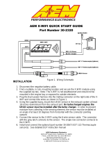
COOLANT GAUGE
The Hayabusa coolant gauge uses a serial communication stream to receive coolant temperature from
the stock ECU. The Infinity supports the serial stream coolant gauge functionality. The corresponding
temperature vs. needle position chart illustrates how the gauge is characterized using the Infinity. The
over temperature light will illuminate at 114 degrees C. The coolant gauge is only supported with the use
of the AEM 30-3550 Hayabusa adapter harness.
INFINITY EMS INSTALLATION
Step 1
Remove the rear cover and seat from the Hayabusa.

2002-2007 Suzuki GSXR1300 Hayabusa
5
© 2015 AEM Performance Electronics
Step 2
Disconnect the battery and remove the Hayabusa ECU, tool
kit (if present), and center connecting piece (shown left,
picture 3).

6
© 2015 AEM Performance Electronics
P/N 30-3550
Step 3
Carefully slide the Infinity into the tail of the Hayabusa as
shown. Affix the Infinity to the tail in the orientation shown in
pictures 2 and 3 using velcro strips.
Step 4
Slide the Infinity Molex 80-pin connector into the Hayabusa
tail and plug it into the Infinity.

2002-2007 Suzuki GSXR1300 Hayabusa
7
© 2015 AEM Performance Electronics
Step 5
Connect the two Hayabusa ECU connectors to the Infinity
adapter harness.
Step 6
Carefully slide the 6-pin UEGO connector through the chassis
and connect to AEM UEGO sensor (if equipped). Ensure all
cables are securely fastened and routed in a safe manner.

8
© 2015 AEM Performance Electronics
P/N 30-3550
Step 7
Carefully route the wheel speed connector through the
chassis to the Hayabusa wheel speed connector in front of
the coolant overflow tank. Unplug the Hayabusa wheel speed
connectors and plug them into the Infinity adapter harness.
Ensure all cables are securely fastened and routed in a safe
manner.

2002-2007 Suzuki GSXR1300 Hayabusa
9
© 2015 AEM Performance Electronics
Step 8
Install the AEM 4 channel coil driver and ensure adequate
heat sinking is used.

10
© 2015 AEM Performance Electronics
P/N 30-3550
Step 9
Locate the battery negative ring terminal (NO FUSE ON
LEAD) from the coil driver connector and connect to the
battery negative terminal.
Step 10
Find the battery positive ring terminal (HAS FUSE ON LEAD)
and install onto the battery positive terminal.

2002-2007 Suzuki GSXR1300 Hayabusa
11
© 2015 AEM Performance Electronics
Step 11
Shown left is what the finished install should look like. Re-
connect the battery, re-install the seat, and rear cover.

12
© 2015 AEM Performance Electronics
P/N 30-3550
PINOUTS
Hayabusa Pinout
Hayabusa Pin
Function
Infinity Pin
Infinity Hardware
1
1
Coil 1
C1-14
Coil 1
2
Coil 2
C1-13
Coil 2
3
Coil 3
C1-12
Coil 3
4
Injector 1
C1-78
Injector 1
5
Injector 2
C1-77
Injector 2
6
Injector 3
C1-76
Injector 3
7
Injector 4
C1-66
Injector 4
8
VC Solenoid
C1-3
Lowside 6
9
Fuel Pump
C1-41
Lowside 0
10
Coil 4
C1-11
Coil 4
11
---
---
---
12
---
---
---
13
---
---
---
14
---
---
---
15
---
---
---
16
---
---
---
17
Switched +12V
C1-48
Ignition Switch
18
Ground
C1-33
Power Ground
19
Starter Relay Input
---
Digital 7 (Clutch Switch)
20
---
---
---
21
Ground
C1-43
Power Ground
22
---
---
---
23
---
---
---
24
---
---
---
25
---
---
---
26
Ground
C1-46
Power Ground
27
Ground
C1-46
Power Ground
28
---
---
---
29
---
---
---
30
---
---
---
31
---
---
---
32
---
---
---
33
---
---
---
34
---
---
---
2
35
Ground
C1-67
Power Ground
36
Crank -
C1-18
VR0 -
37
Cam +
C1-20
VR1 +
38
---
---
---
39
---
---
---

2002-2007 Suzuki GSXR1300 Hayabusa
13
© 2015 AEM Performance Electronics
40
---
---
---
41
---
---
---
42
---
---
---
43
Crank +
C1-17
VR0 +
44
Cam -
C1-19
VR1 -
45
---
---
---
46
---
---
---
47
---
---
---
48
Sensor 5V
C1-49
+5V Ref
49
Throttle Position
C1-51
Analog 7
50
Air Temperature
C1-39
Analog 2
51
Water Temperature
C1-38
Analog 1
52
Barometric Pressure
C1-75
Analog 10
53
---
---
---
54
Sensor Ground
C1-23
Analog Ground 1
55
Tacho
C1-2
Lowside 5
56
Dash Serial
C1-30
Serial Tx (Digital 5)
57
Gear Position
C1-74
Analog 11
58
MAP Sensor
C1-52
Analog 8
59
Tip Over Sensor
C1-70
Analog 18
60
---
---
---
Infinity 6 Pinout
Pin
Infinity-6 Hardware
2002-2007 Hayabusa
Function
1
Lowside 4
VSS Connector Pin 3
Speedometer
2
Lowside 5
C2-55
Tacho
3
Lowside 6
C2-8
VCSV
4
Lowside 7
---
---
5
UEGO1 Heat
UEGO-4
UEGO1 Heat-
6
UEGO1 IA
UEGO-2
UEGO1 IA
7
UEGO1 IP
UEGO-6
UEGO1 IP
8
UEGO1 UN
UEGO-1
UEGO1 UN
9
UEGO1 VM
UEGO-5
UEGO1 VM
10
+12V Perm Power
ECU Relay Pin 85
Batt. Perm Power
11
Coil 4
Coil Driver Pin 5
Coil_3 (Cyl 4)
12
Coil 3
Coil Driver Pin 4
Coil_2 (Cyl 3)
13
Coil 2
Coil Driver Pin 2
Coil_1 (Cyl 2)
14
Coil 1
Coil Driver Pin 1
Coil_0 (Cyl 1)
15
Coil 6
---
---
16
Coil 5
---
---
17
VR0 (+) - Crank
C2-43
Crank VR0 +
18
VR0 (-) - Crank
C2-36
Crank VR0 -
19
VR1 (-) - Cam
C2-44
Cam VR1 -
20
VR1 (+) - Cam
C2-37
Cam VR1 +
21
Lowside 2
AUX Pin 12
Lowside_2 (Aux)
22
Lowside 3
AUX Pin 11
Lowside_3 (Aux)
23
Sensor GND
C2-54
Sensor Ground

14
© 2015 AEM Performance Electronics
P/N 30-3550
24
Sensor GND
AUX Pin 3
Sensor Ground
25
Digital 0 - Crank
---
---
26
Digital 1 - Cam1
---
---
27
Digital 2 - Cam2
---
---
28
Digital 3
VSS Connector Pin 3
Digital_3 (Vehicle Speed)
29
Digital 4
AUX Pin 9
Digital_4 (Aux)
30
Digital 5
C2-56
Serial Tx (Coolant Temp)
31
Digital 6
AUX Pin 6
Digital_6 (Aux)
32
Digital 7
C2-19
Clutch Switch
33
GND
C2-18
Power Ground
34
CAN A -
---
---
35
CAN A +
---
---
36
CAN B -
---
---
37
CAN B +
---
---
38
Analog 1
C2-51
Coolant Temp
39
Analog 2
C2-50
Air Temp
40
Analog 3
AUX Pin 2
Temp_3 (Aux)
41
Lowside 0
C2-9
Fuel Pump
42
Lowside 1
AUX Pin 7
Lowside_1 (Aux)
43
GND
C2-21
Power Ground
44
Knock 0
---
---
45
Knock 1
---
---
46
GND
C2-26 (Spliced)
Power Ground
47
12V_Relay_Control
Relay Pin 86
12V+_Relay_Control
48
+12V SW (Ign Switch)
C2-17
Ignition Switch
49
+5V_Out
C2-48 (Spliced)
+5V_Out
50
+5V_Out
AUX Pin 4
+5V_Out
51
Analog 7
C2-49
Throttle Position
52
Analog 8
C2-58
MAP Sensor
53
Analog 9
AUX Pin 1
Analog_9 (Aux)
54
VR2 (+) - Driven Wheel
---
---
55
VR2 (-) - Driven Wheel
---
---
56
VR3 (-) - Tag Wheel
---
---
57
VR3 (+) - Tag Wheel
---
---
58
Highside 0
---
---
59
Stepper_1B
---
---
60
Stepper_2B
---
---
61
HBridge0_0
---
---
62
HBridge0_1
---
---
63
+12V
Relay Pin 87
+12V
64
Injector 6
---
---
65
Injector 5
---
---
66
Injector 4
C2-7
Injector_3 (Cyl 4)
67
GND
C2-35
Power Ground
68
+12V
---
---
69
Analog 19
---
---
70
Analog 18
C2-59
Tip Over Sensor
71
Analog 16
AUX Pin 10
Analog_16 (Aux)
72
Harness_Flash_Enable
---
---
73
Analog 13
AUX Pin 5
Analog_13 (Aux)
74
Analog 11
C2-57
Gear
75
Analog 10
C2-52
Baro Sensor
76
Injector 3
C2-6
Injector_2 (Cyl 3)

2002-2007 Suzuki GSXR1300 Hayabusa
15
© 2015 AEM Performance Electronics
77
Injector 2
C2-5
Injector_1 (Cyl 2)
78
Injector 1
C2-4
Injector_0 (Cyl 1)
79
Stepper_2A
---
---
80
Stepper_1A
---
---
Aux Connector Pinout
Aux
Pin
Infinity
Pin
Infinity Hardware
Default Function
1
C1-53
Analog 9
Fuel Pressure
2
C1-40
Analog Temp 3
Oil Temperature
3
C1-24
Sensor Ground
Sensor Ground
4
C1-50
+5V
+5V
5
C1-73
Analog 13
Oil Pressure
6
C1-31
Digital 6
General Frequency/Duty Input
7
C1-42
Lowside 1
Boost Control
8
C1-63
+12V
+12V
9
C1-29
Digital 4
Turbo Speed
10
C1-71
Analog 16
Mode Switch
11
C1-22
Lowside 3
General Purpose Output
12
C1-21
Lowside 2
General Purpose Output
Miscellaneous Pinouts
LAMBDA 1
Lambda Pin
Infinity Pin
Default Pin Function
1
C1-8
UEGO1 UN
2
C1-6
UEGO1 IA
3
---
+12V
4
C1-5
UEGO1 Heat
5
C1-9
UEGO1 VM
6
C1-7
UEGO1 IP
AEMNet
Deutsch Pin
Infinity Pin
Default Pin Function
1
C1-34
CAN A-
2
C1-35
CAN A+
3
---
+12V
4
---
Ground

16
© 2015 AEM Performance Electronics
P/N 30-3550
FLASH ENABLE
Deutsch Pin
Infinity Pin
Default Pin Function
1
C1-72
Harness Flash Enable
2
C1-10
Permanent Power
Infinity Pin Numbering
Viewed from Wire Side
Hayabusa Pin Numbering
Viewed from Wire Side

2002-2007 Suzuki GSXR1300 Hayabusa
17
© 2015 AEM Performance Electronics
12 MONTH LIMITED WARRANTY
Advanced Engine Management Inc. warrants to the consumer that all AEM High Performance products
will be free from defects in material and workmanship for a period of twelve (12) months from date of the
original purchase. Products that fail within this 12-month warranty period will be repaired or replaced at
AEM’s option, when determined by AEM that the product failed due to defects in material or
workmanship. This warranty is limited to the repair or replacement of the AEM part. In no event shall this
warranty exceed the original purchase price of the AEM part nor shall AEM be responsible for special,
incidental or consequential damages or cost incurred due to the failure of this product. Warranty claims
to AEM must be transportation prepaid and accompanied with dated proof of purchase. This warranty
applies only to the original purchaser of product and is non-transferable. All implied warranties shall be
limited in duration to the said 12-month warranty period. Improper use or installation, accident, abuse,
unauthorized repairs or alterations voids this warranty. AEM disclaims any liability for consequential
damages due to breach of any written or implied warranty on all products manufactured by AEM.
Warranty returns will only be accepted by AEM when accompanied by a valid Return Merchandise
Authorization (RMA) number. Product must be received by AEM within 30 days of the date the RMA is
issued.
UEGO oxygen sensors are considered wear items and are not covered under warranty.
Please note that before AEM can issue an RMA for any electronic product, it is first necessary for the
installer or end user to contact the EMS tech line at 1-800-423-0046 to discuss the problem. Most
issues can be resolved over the phone. Under no circumstances should a system be returned or a RMA
requested before the above process transpires.
AEM will not be responsible for electronic products that are installed incorrectly, installed in a non-
approved application, misused, or tampered with.
Any AEM electronics product can be returned for repair if it is out of the warranty period. There is a
minimum charge of $50.00 for inspection and diagnosis of AEM electronic parts. Parts used in the repair
of AEM electronic components will be extra. AEM will provide an estimate of repairs and receive written
or electronic authorization before repairs are made to the product.
/