
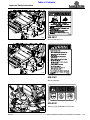
Table of Contents
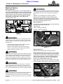
Cover photo may show optional equipment
not supplied with standard unit.
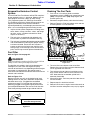
Read the Operator’s Manual entirely. When you
see this symbol, the subsequent instructions and
warnings are serious - follow without exception.
Your life and the lives of others depend on it!
!
© Copyright 2015 Printed
ZSR54, & ZSR60 Accu-Z Razor
®
Zero Turn Mowers
357-344M
27751
Operator’s Manual
12/15/15

Table of Contents
ZSR54, & ZSR60 Accu-Z Razor
®
Zero Turn Mowers 357-344M
12/15/15
© Copyright 2015 All rights Reserved
Land Pride provides this publication “as is” without warranty of any kind, either expressed or implied. While every precaution has been taken in the
preparation of this manual, Land Pride assumes no responsibility for errors or omissions. Neither is any liability assumed for damages resulting from the use
of the information contained herein. Land Pride reserves the right to revise and improve its products as it sees fit. This publication describes the state of this
product at the time of its publication, and may not reflect the product in the future.
Land Pride is a registered trademark.
All other brands and product names are trademarks or registered trademarks of their respective holders.
Printed in the United States of America.
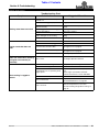
Table of Contents
Important Safety Information . . . . . . . . . . . . . 1
Safety Labels . . . . . . . . . . . . . . . . . . . . . . . . . . . . . 4
Introduction . . . . . . . . . . . . . . . . . . . . . . . . . . . 8
Application . . . . . . . . . . . . . . . . . . . . . . . . . . . . . . . 8
Using This Manual . . . . . . . . . . . . . . . . . . . . . . . . . . 8
Owner Assistance . . . . . . . . . . . . . . . . . . . . . . . . . . 8
Serial Number . . . . . . . . . . . . . . . . . . . . . . . . . . . 8
Section 1: Assembly & Set-up . . . . . . . . . . . 10
Uncrating Instructions . . . . . . . . . . . . . . . . . . . . . . 10
Torque Requirements . . . . . . . . . . . . . . . . . . . . . . 10
Discharge Chute Assembly . . . . . . . . . . . . . . . . . . 10
Folding ROPS . . . . . . . . . . . . . . . . . . . . . . . . . . . . 10
Electrical Cable Connection . . . . . . . . . . . . . . . . . 11
Engine Preparations . . . . . . . . . . . . . . . . . . . . . . . 11
Section 2: Operating Procedures . . . . . . . . 12
Mower Features . . . . . . . . . . . . . . . . . . . . . . . . . . 12
Operating Checklist . . . . . . . . . . . . . . . . . . . . . . . . 13
Instrumentation . . . . . . . . . . . . . . . . . . . . . . . . . . . 13
Engine Oil Pressure Light . . . . . . . . . . . . . . . . . . 13
Hour Meter . . . . . . . . . . . . . . . . . . . . . . . . . . . . . 13
Controls . . . . . . . . . . . . . . . . . . . . . . . . . . . . . . . . . 13
Engine Starting . . . . . . . . . . . . . . . . . . . . . . . . . . . 15
Engine Shut-Down Sequence . . . . . . . . . . . . . . . . 15
Safety Start Interlock System . . . . . . . . . . . . . . . . 16
Driving the Mower . . . . . . . . . . . . . . . . . . . . . . . . . 16
Accessing Area Beneath the Seat . . . . . . . . . . . . . 18
Moving Mower with Stalled Engine . . . . . . . . . . . . 18
Safe Operating Instructions . . . . . . . . . . . . . . . . . . 19
General Operating Information . . . . . . . . . . . . . . . 21
Section 3: Adjustments . . . . . . . . . . . . . . . . 22
Torque Requirements . . . . . . . . . . . . . . . . . . . . . . 22
Tire Pressure . . . . . . . . . . . . . . . . . . . . . . . . . . . . . 22
Front Floating Axle . . . . . . . . . . . . . . . . . . . . . . . . 22
Steering Adjustments . . . . . . . . . . . . . . . . . . . . . . 23
Lower Control Lever . . . . . . . . . . . . . . . . . . . . . . 23
Upper Control Lever . . . . . . . . . . . . . . . . . . . . . . 24
Seat Adjustment . . . . . . . . . . . . . . . . . . . . . . . . . . 24
Ground Drive Belt Adjustment . . . . . . . . . . . . . . . . 25
Deck Drive Belt Adjustment . . . . . . . . . . . . . . . . . . 25
Deck Adjustments . . . . . . . . . . . . . . . . . . . . . . . . . 26
Deck Cutting Height And Leveling . . . . . . . . . . . 26
Deck Lift Assist Springs . . . . . . . . . . . . . . . . . . . 27
Anti-Scalp Rollers . . . . . . . . . . . . . . . . . . . . . . . . 28
Cutting Height Settings . . . . . . . . . . . . . . . . . . . . . 28
Section 4: Options & Accessories . . . . . . . . 29
Folding Soft Top Canopy . . . . . . . . . . . . . . . . . . . . 29
Electric Deck Lift . . . . . . . . . . . . . . . . . . . . . . . . . . 29
Mulching Kit . . . . . . . . . . . . . . . . . . . . . . . . . . . . . . 29
Light Kit . . . . . . . . . . . . . . . . . . . . . . . . . . . . . . . . . 29
Inductive Tachometer . . . . . . . . . . . . . . . . . . . . . . 29
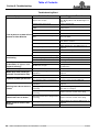
Section 5: Maintenance & Lubrication . . . . . 30
Maintenance . . . . . . . . . . . . . . . . . . . . . . . . . . . . . 30
Maintenance Safety . . . . . . . . . . . . . . . . . . . . . . . . 30
Maintenance Schedule . . . . . . . . . . . . . . . . . . . . . 31
Maintenance Locations . . . . . . . . . . . . . . . . . . . . . 32
Torque Requirements . . . . . . . . . . . . . . . . . . . . . . 34
Tires . . . . . . . . . . . . . . . . . . . . . . . . . . . . . . . . . . . 34
Electrical System . . . . . . . . . . . . . . . . . . . . . . . . . . 35
Hydrostatic Drive System . . . . . . . . . . . . . . . . . . . 36
Hydraulic Oil Level Check . . . . . . . . . . . . . . . . . . . 36
Transaxle Oil and Filter Change . . . . . . . . . . . . . . 36
Transaxle Purging Procedures . . . . . . . . . . . . . . . 37
Fuel System . . . . . . . . . . . . . . . . . . . . . . . . . . . . . 38
Evaporative Emission Control System . . . . . . . . . . 39
Fuel Filter . . . . . . . . . . . . . . . . . . . . . . . . . . . . . . . 39
Draining The Fuel Tank . . . . . . . . . . . . . . . . . . . . . 39
Belt Maintenance . . . . . . . . . . . . . . . . . . . . . . . . . . 40
Deck Drive Belt Removal & Installation . . . . . . . 40
Ground Drive Belt Removal & Installation . . . . . . 40
Mower Blade Maintenance . . . . . . . . . . . . . . . . . . 42
General Engine Maintenance . . . . . . . . . . . . . . . . 44
Engine Oil and Oil Filter . . . . . . . . . . . . . . . . . . . . . 44
Check Engine Oil . . . . . . . . . . . . . . . . . . . . . . . . 44
Change Engine Oil . . . . . . . . . . . . . . . . . . . . . . . 44
Engine Air Filter . . . . . . . . . . . . . . . . . . . . . . . . . . . 45
Internal Type Air Filters . . . . . . . . . . . . . . . . . . . 45
Canister Type Air Filters . . . . . . . . . . . . . . . . . . . 45
Air Filter Handling . . . . . . . . . . . . . . . . . . . . . . . . . 46
End of Season & Long Term Storage . . . . . . . . . . 47
New Season Preparation . . . . . . . . . . . . . . . . . . . . 47
Lubrication Points . . . . . . . . . . . . . . . . . . . . . . . . . 48
Section 6: Specifications & Capacities . . . . . 50
Section 7: Features & Benefits . . . . . . . . . . . 53
Section 8: Troubleshooting . . . . . . . . . . . . . . 55
Section 9: Torque & Tire Inflation Charts . . 57
Section 10: Warranty . . . . . . . . . . . . . . . . . . . 58

1
Important Safety Information
ZSR54, & ZSR60 Accu-Z Razor
®
Zero Turn Mowers 357-344M
Table of Contents
12/15/15
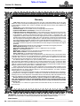
Important Safety Information
▲
These are common practices that may or may not be applicable to the products described in
this manual.
Safety at All Times
Thoroughly read and understand
the instructions given in this
manual before operation. Refer to
the “Safety Label” section, read all
instructions noted on them.
Do not allow anyone to operate
this equipment who has not fully
read and comprehended this
manual and who has not been
properly trained in the safe
operation of the equipment.
▲ Operator should be familiar with all
functions of the mower.
▲ The operator must not use drugs
or alcohol as they can change the
alertness or coordination of that
person while operating equipment.
The operator should, if taking over-
the-counter drugs, seek medical
advice on whether he/she can
safely operate the equipment.
▲ Operate mower from the driver’s
seat only.
▲ Make sure all guards and shields
are in place and secured before
operating the mower.
▲ Do not leave mower unattended
with engine running.
▲ Dismounting from a moving
mower can cause serious injury or
death.
▲ Do not allow anyone to stand
between mower and equipment
while backing up to hitch mower to
the equipment.
▲ Keep hands, feet, and clothing
away from power-driven parts.
▲ Wear snug fitting clothing to avoid
entanglement with moving parts.
▲ Watch out for wires, rocks trees,
etc., when using the mower. Make
sure all persons are clear of
working area.
▲ Do not carry passengers on the
mower at any time.
▲ Turning mower too tight may
cause hitched machinery to ride
up on wheels. This could result in
injury or equipment damage.
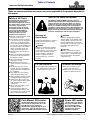
Look For The Safety Alert Symbol
The SAFETY ALERT SYMBOL indicates there is a
potential hazard to personal safety involved and extra
safety precaution must be taken. When you see this
symbol, be alert and carefully read the message that
follows it. In addition to design and configuration of
equipment, hazard control, and accident prevention are
dependent upon the awareness, concern, prudence, and
proper training of personnel involved in the operation,
transport, maintenance, and storage of equipment.
OFF
R
E
M
OV
E
Shutdown and Storage
▲ Put mower in park, turn off
engine, and remove key.
▲ Store mower in a area where
children normally do not play.
Parts Manual QR Locator
The QR (Quick Reference) code on the
cover and to the left will take you to the
Parts Manual for this equipment.
Download the appropriate App on your
smart phone, open the App, point your
phone on the QR code and take a picture.
Dealer QR Locator
The QR code on the left will
link you to available dealers
for Land Pride products.
Refer to Parts Manual QR
Locator on this page for
detailed instructions.
!
Be Aware of
Signal Words
A Signal word designates a degree or
level of hazard seriousness. The
signal words are:
Indicates an imminently hazardous
situation which, if not avoided, will
result in death or serious injury. This
signal word is limited to the most
extreme situations, typically for
machine components that, for
functional purposes, cannot be
guarded.
!
DANGER
Indicates a potentially hazardous
situation which, if not avoided, could
result in death or serious injury, and
includes hazards that are exposed
when guards are removed. It may also
be used to alert against unsafe
practices.
Indicates a potentially hazardous
situation which, if not avoided, may
result in minor or moderate injury. It
may also be used to alert against
unsafe practices.
!
WARNING
!
CAUTION
For Your Protection
▲ Thoroughly read and understand
the “Safety Label” section, read
all instructions noted on them.

2
Important Safety Information
ZSR54, & ZSR60 Accu-Z Razor
®
Zero Turn Mowers 357-344M
Table of Contents
12/15/15
These are common practices that may or may not be applicable to the products described in
this manual.
Avoid High
Pressure Fluids Hazard
▲ Escaping fluid under pressure can
penetrate the skin causing serious
injury.
▲ Avoid the hazard by relieving
pressure before disconnecting
hydraulic lines or performing work
on the system.
▲ Make sure all hydraulic fluid
connections are tight and all
hydraulic hoses and lines are in
good condition before applying
pressure to the system.
▲ Use a piece of paper or
cardboard, NOT BODY PARTS, to
check for suspected leaks.
▲ Wear protective gloves and safety
glasses or goggles when working
with hydraulic systems.
▲ DO NOT DELAY. If an accident
occurs, see a doctor familiar with
this type of injury immediately.
Any fluid injected into the skin
or eyes must be
treated within a few
hours or gangrene
may result.
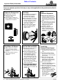
Keep Riders Off Mowers
▲ Riders obstruct the operator’s
view, they could be struck by
foreign objects or thrown from the
machine.
▲ Never allow children under 16
years of age to operate
equipment.
Use Seat Belt and ROPS
▲ Operate only mowers equipped
with Roll-Over Protective
Structure (ROPS) and seat belt.
▲ Fasten seat belt snugly and
securely to help protect operator
from being thrown, crushed, or
severely injured if a rollover
occurs; and from falling off the
mower and being ran over. Not
using the seat belt & ROPS can
result in serious injury or death.
▲ Wearing protective equipment
such as safety shoes, safety
glasses, hard hat, and ear plugs is
highly recommended.
▲ LOW STRUCTURES CAN FLIP
MOWER OVER BACKWARDS.
Lower ROPS to drive under low
structures such as tree limbs and
doorways.
Prepare for Emergencies
▲ Be prepared if a fire starts.
▲ Keep a first aid kit and fire
extinguisher handy.
▲ Keep emergency numbers for
doctor, ambulance, hospital, and
fire department near phone.
911
Wear
Protective Equipment
▲ Wear protective clothing and
equipment appropriate for the job.
Clothing should be snug fitting
without fringes and pull strings to
avoid entanglement with moving
parts.
▲ Prolonged exposure to loud noise
can cause hearing impairment or
hearing loss. Wear suitable
hearing protection such as
earmuffs or earplugs.
▲ Operating equipment safely
requires the operator’s full
attention. Avoid wearing radio
headphones while operating
machinery.
Tire Safety
▲ Tire changing can be dangerous
and should be preformed by
trained personnel using the
correct tools and equipment.
▲ When inflating tires, use a clip-on
chuck and extension hose long
enough to allow you to stand to
one side and NOT in front of or
over the tire assembly. Use a
safety cage if available.
▲ When removing and installing
wheels, use wheel handling
equipment adequate for the
weight involved.

3
Important Safety Information
ZSR54, & ZSR60 Accu-Z Razor
®
Zero Turn Mowers 357-344M
Table of Contents
12/15/15
These are common practices that may or may not be applicable to the products described in
this manual.
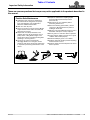
Practice Safe Maintenance
▲ Understand safe and correct maintenance
procedures before doing work. Use proper
tools and equipment, refer to Operator’s
Manual for additional information.
▲ Work in a clean dry area.
▲ Never run mower in an enclosed area. Mower
engine exhaust emits carbon monoxide and
other poisonous gases.
▲ Keep hands, feet, body extremities, and
clothing away from all moving parts such as
pulleys, belts, cutting blades, engine, and
wheels. Don’t wear loose fitting clothing while
operating or servicing mower.
▲ Put mower in neutral, set park brake,
disengage blades, turn off engine, remove
switch key and wait for all moving components
to stop before performing maintenance on the
mower.
▲ Repairs or maintenance requiring engine
power should be performed by trained
personnel only.
▲ Allow mower to cool completely before
performing maintenance.
▲ Disconnect battery ground cable (-) before
servicing or adjusting electrical systems or
welding on the mower.
▲ Observe safe fuel handling precautions. Fuel is
flammable and vapors are very explosive.
▲ Do not grease or oil mower while in operation.
▲ Inspect all parts. Make sure parts are in good
condition and installed properly.
▲ Remove buildup of grease, oil, or debris.
▲ Replace all guards and floor pan before putting
mower back into service.
▲ Remove all tools and unused parts from mower
before operation.

4
Important Safety Information
ZSR54, & ZSR60 Accu-Z Razor
®
Zero Turn Mowers 357-344M
Table of Contents
12/15/15
Safety Labels
Your Zero Turn Riding Mower comes equipped with all safety
labels in place. They were designed to help you safely operate
your implement. Read and follow their directions.
1. Keep all safety labels clean and legible.
2. Refer to this section for proper label placement. Replace
all damaged or missing labels. Order new labels from your
nearest Land Pride dealer. To find your nearest dealer,
visit our dealer locator at www.landpride.com.
3. Some new equipment installed during repair requires
safety labels to be affixed to the replaced component as
specified by Land Pride. When ordering new components
make sure the correct safety labels are included in the
request.
4. Refer to this section for proper label placement.
To install new labels:
a. Clean surface area where label is to be placed.
b. Spray soapy water onto the cleaned area.
c. Peel backing from label and press label firmly onto the
surface.
d. Squeeze out air bubbles with edge of a credit card or
with a similar type of straight edge.
838-829C
Caution: Do Not Power Wash
838-303C
Danger: Battery
(Beneath The Seat Mount)
818-543C
Danger: Guard Missing
(Beneath The Seat Mount)
27753
27753
27755


7
Important Safety Information
ZSR54, & ZSR60 Accu-Z Razor
®
Zero Turn Mowers 357-344M
Table of Contents
12/15/15
838-444C
Danger: Muffler Hot
(Both Sides of Engine)
Floor platform & Pulley Shields
have been removed to show decals
27757
27823
27757
818-543C
Danger: Guard Missing
3- Places
848-268C
Warning: Safe Operating Instructions

8
Introduction
ZSR54, & ZSR60 Accu-Z Razor
®
Zero Turn Mowers 357-344M
Table of Contents
12/15/15
Introduction
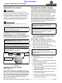
Serial Number
Model No. _____________Serial No. ______________
For quick reference and prompt service, record model
number and serial number in the spaces provided above
and again on warranty page 58. Always provide model
number and serial number when ordering parts and in all
correspondences with your Land Pride dealer. Refer to
Figure 1 for location of your serial number plate.
Serial Number Plate Location
Figure 1
For parts and service to your mower engine, contact
your nearest engine dealer or call Customer Service
Hotline provided below.
Owner’s Manual Part No.
Kawasaki - 18.5 HP . . . . 99920-2256
Kawasaki - 23 HP. . . . . . 99920-2250
Kawasaki - 23.5 HP . . . . 99920-2251
Service Manual Part No.
Kawasaki - 18.5 HP . . . . 99924-2094-01
Kawasaki - 23 HP. . . . . . 9992V-2093-03
Kawasaki - 23.5 HP . . . . 9992V-2093-03
Service Hotline Phone No.
Kawasaki . . . . . . . . . . . . 1-800-433-5640
27820
Land Pride welcomes you to the growing family of new
product owners. This mower has been designed with
care and built by skilled workers using quality materials.
Proper assembly, maintenance, and safe operating
practices will help you get years of satisfactory use from
this machine.
Application
The Land Pride Razor ZSR54 & ZSR60 residential class
mowers are compact in size and ideal for homeowner
grass maintenance. The Razor is a true zero-turn mower:
When mowing alongside a building or landscaping, the
Razor allows you to turn away and not hit anything with
the rear end. Control lever heights are also adjustable,
making the mower comfortable to handle.
See “Specifications & Capacities” on page 50 and
“Features & Benefits” on page 53 for additional
information and performance enhancing options.
Using This Manual
•
This Operator’s Manual is designed to help familiarize
the operator with safety, assembly, operation,
adjustments, troubleshooting, and maintenance. Read
this manual and follow the recommendations to help
ensure safe and efficient operation.
• The information contained within this manual was
current at the time of printing. Some parts may change
slightly to assure you of the best performance.
• To order a new Operator’s or Parts Manual, contact
your authorized dealer. Manuals can also be
downloaded, free-of-charge, from our website at
www.landpride.com
Terminology
“Right” or “Left” as used in this manual is determined by
facing forward while sitting in the operator seat unless
otherwise stated.
Definitions
Owner Assistance
The Online Warranty Registration should be completed
by the dealer at the time of purchase. This information is
necessary to provide you with quality customer service.
The parts on your Zero Turn Riding Mower have been
specially designed by Land Pride and should only be
replaced with genuine Land Pride parts. Contact a Land
Pride dealer if customer service or repair parts are
required. Your Land Pride dealer has trained personnel,
repair parts, and equipment needed to service the
implement.
IMPORTANT: A special point of information related
to the following topic. Land Pride’s intention is this
information must be read & noted before continuing.
NOTE: A special point of information that the
operator should be aware of before continuing.

9
Introduction
ZSR54, & ZSR60 Accu-Z Razor
®
Zero Turn Mowers 357-344M
Table of Contents
12/15/15
Further Assistance
Your dealer wants you to be satisfied with your new
mower. If for any reason you do not understand any part
of this manual or are not satisfied with the service
received, the following actions are suggested:
1. Discuss the matter with your dealership service
manager making sure that person is aware of any
problems you may have and has had the opportunity
to assist you.
2. If you are still not satisfied, seek out the owner or
general manager of the dealership, explain the
problem, and request assistance.
3. For further assistance write to:
Land Pride Service Department
1525 East North Street
P.O. Box 5060
Salina, Ks. 67402-5060
E-mail address
lpservicedept@landpride.com

10
Section 1: Assembly & Set-up
ZSR54, & ZSR60 Accu-Z Razor
®
Zero Turn Mowers 357-344M
Table of Contents
12/15/15
Section 1: Assembly & Set-up
Uncrating Instructions
The shipping crate is assembled together with nails. It
can be disassembled by prying or cutting the lumber
apart. Be careful not to scratch, dent, or cut mower
and/or seat during disassembly. It is best if two people
are present while disassembling the crate.
1. Remove end and side panels from the crate.
2. Cut metal bands securing the front and rear wheels
to the crate floor. Discard bands.
3. Lift mower from crate floor with a hoist or other
suitable lifting device.
Torque Requirements
Refer to “Torque Values Chart” on page 57 to
determine correct torque values for common bolts. See
“Additional Torque Values” at bottom of chart for
exceptions to standard torque values.
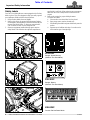
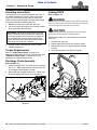
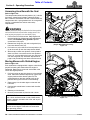
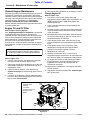
Discharge Chute Assembly
Refer to Figure 1-1:
1. Attach discharge chute (#1) to the deck by inserting
3/8"-16 x 1" GR5 round head square neck bolts (#2)
up through the deck bottom as shown.
2. Secure with 3/8" flanged locknuts (#3). Tighten nuts
to correct torque. See Torque Chart on page 57.
Discharge Chute Assembly
Figure 1-1
IMPORTANT: Do not drive mower off the crate floor,
as this can bend or break components underneath
the mower, especially the transaxles. Lift mower off
the crate floor with a hoist or other suitable lifting
device. Be careful not to damage the paint and seat
while lifting the unit off the crate floor.
30337
Folding ROPS
Refer to Figure 1-2:
!
DANGER
Low structures can make contact with the ROPS and flip the
mower over backwards. Fold ROPS down when driving under
low structures such as tree limbs and doorways.
!
CAUTION
Keep hands and other body extremities away from hinged
pinch points while folding and unfolding ROPS.
ROPS locking knobs (#1) are included in an attached
parts bag.
1. Remove hitch pins (#2).
2. Rotate upper ROPS frame up to position shown.
3. Reinsert hitch pins (#2) and secure with attached
hairpins.
4. Install locking knobs (#1) and hand tighten.
Folding ROPS Set-up Assembly
Figure 1-2
33201

11
Section 1: Assembly & Set-up
ZSR54, & ZSR60 Accu-Z Razor
®
Zero Turn Mowers 357-344M
Table of Contents
12/15/15
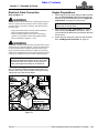
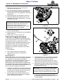
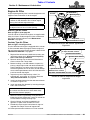
Electrical Cable Connection
Refer to Figure 1-3:
!
WARNING
Incorrect battery cable connections can damage the mower’s
electrical system and cause battery cables to spark. Sparks
around a battery can result in a battery gas explosion and
personal injury.
• Always disconnect negative (black) cable from battery
before disconnecting positive (red) cable.
• Always reconnect positive (red) cable to the battery’s
positive (+) post before reconnecting negative (black)
cable to the battery’s negative (-) post.
!
WARNING
Keep battery terminals from touching any metal mower parts
when removing or installing battery. Do not allow metal tools
to short between battery terminals and metal mower parts.
Shorts caused by battery terminals or metal tools touching
metal mower components can cause sparks. Sparks can cause
a battery gas explosion which can result in personal injury.
Connect black battery cable to the battery’s negative post
with 1/4"-20 x 3/4" GR5 hex head serrated screw, flat
washer, lock washer, and nut before starting the mower.
Tighten hex nut to the correct torque.
Connecting the Negative Cable
Figure 1-3
IMPORTANT: The black negative battery cable is
disconnected before leaving the factory and is to be
disconnected after initial dealer set-up to prevent
battery discharge while sitting on the dealer lot.
Negative Post
Black Battery
Cable
Red Battery
Cable
27753
Positive Post Located
Under Red Cover
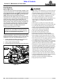
Engine Preparations
1. Check engine oil level at the dipstick. Add oil if below
full mark. Do not overfill. Refer to Engine Operator’s
Manual for oil recommendation and to “Engine Oil
and Oil Filter” on page 44 in this manual.
2. See instructions under “Fuel System” on page 38.
After reading “Fuel System” instructions, add a
small amount of gasoline with a fuel stabilizer to one of
the fuel tanks.
3. Switch fuel tank valve to the fuel tank with gasoline.
See “Left/Right Fuel Tank Valve” on page 14.
NOTE: Mowers are shipped from the factory
without fuel in the fuel tanks.

12
Section 2: Operating Procedures
ZSR54, & ZSR60 Accu-Z Razor
®
Zero Turn Mowers 357-344M
Table of Contents
12/15/15
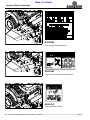
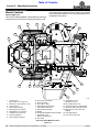
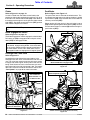
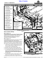
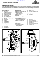
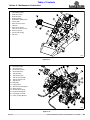
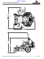
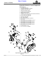
Mower Features
Refer to Figure 2-1:
Your Zero Turn Riding Mower is designed with innovative
and state-of-the-art features. Knowing the location and
how these features work will make handling your mower
more comfortable. Below is a list of major features to be
reviewed in this section.
Section 2: Operating Procedures
Zero Turn Riding Mower Features
Figure 2-1
27764
12
3
19
16
1
13
2
20
4
14
5
6
8
11
9
18
12
7
8
10
17
25
21
21
15
23
22
3
24
24
1. Control Panel
(See Figure 2-2 on page 13)
2. Battery (Located under the seat)
3. Control Levers
4. Deck Height Indicator
5. Discharge Chute (Guard)
6. Right Deck Cover (Guard)
7. Left Deck Cover (Guard)
8. Anti-Scalp Wheels
9. Deck Height Gauge Bar
10. Floor Platform (Guard)
11. Deck Lift Pedal
12. Fuel Caps & Tanks
13. Left/Right Fuel Tank Valve
(Below Right Arm Rest)
14. Seat Platform (Guard)
15. Muffler
16. Rear Bumper/Muffler Shield (Guard)
17. Park Brake Lever
(Below Left Arm Rest)
18. Front Axle
19. Seat Release Latch
(Behind the Seat)
20. Seat Adjustment Latch
21. Expansion Tank for Hydraulic Oil
22. Seat Belt (Below Both Arm Rest)
23. Roll Over Protective Structure
(ROPS)
24. Fuel Sight Gauge
25. Front Pivot Axle Locks

13
Section 2: Operating Procedures
ZSR54, & ZSR60 Accu-Z Razor
®
Zero Turn Mowers 357-344M
Table of Contents
12/15/15
Operating Checklist
Hazard control and accident prevention are dependent
upon awareness, concern, prudence, and proper training
involved in operation, transport, maintenance, and
storage of the riding mower. Therefore, it is absolutely
essential that no one operates the mower without first
having read, fully understood, and become totally familiar
with the Operator’s Manual. Make sure the operator has
paid particular attention to:
• Important Safety Information, page 1
• Section 1: Assembly & Set-up, page 10
• Section 2: Operating Procedures, page 12
• Section 3: Adjustments, page 22
• Section 5: Maintenance & Lubrication, page 30
The following Operating Checklist should be performed
before operating your mower:
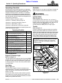
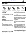
Instrumentation
Engine Oil Pressure Light
Refer to to Figure 2-2:
This light comes on when ignition switch is placed in RUN
position and stays lit until the engine is running with safe
oil pressure. Shut engine off immediately if light comes
on during operation. Locate and correct problem before
using the mower.
Hour Meter
Refer to Figure 2-2:
The hour meter registers 1/10 hour increments up to
9,999.9 total hours. The meter is connected to the ignition
switch and records accumulative time only while the
engine is running.
A plastic film covers the hour meter window. It protects
the window from scratches during shop assembly and
shipping. This covering should be removed by the owner
before placing mower into service.
Operating Checklist
✔
Check Ref.
Carefully read and follow all safety rules.
Refer to "Important Safety Information".
Page 1
Make sure all guards and shields are in place.
Refer to "Mower Features".
Page 12
Make all required adjustments.
Refer to "Section 3: Adjustments".
Page 22
Read and follow all operating procedures.
Refer to "Section 2: Operating Procedures".
Page 12
Check mower safety start interlock system daily
prior to operation.
Page 16
Perform all maintenance and lubrications.
Refer to "Section 5: Maintenance & Lubrication".
Page 30
Make sure their are no hydraulic leaks on the unit.
Refer to "Avoid High Pressure Fluids Hazard".
Page 2
Check blade for nicks and sharpness.
Refer to "Mower Blade Maintenance".
Page 42
Check mower initially and periodically for loose
bolts and pins. Refer to "Torque Values Chart".
Page 57
Controls
Refer to Figure 2-1 on page 12 and Figure 2-2 below for
general location of controls described in this section.
!
WARNING
Do not operate mower while smoking.
Ignition Switch
Refer to Figure 2-2:
A three position ignition switch: off, run, and start is
provided. With key inserted, rotate it clockwise to START
position; release key when engine starts and switch will
automatically return to RUN position. Turn key
counterclockwise to OFF position to stop engine.
Throttle
Refer to Figure 2-2:
A cable is linked from engine to throttle for controlling
engine speed. Move throttle lever forward to increase
engine rpm and rearward to decrease rpm. Always travel
and cut grass with throttle set at full engine rpm speed.
Decrease travel speed by pulling back on the control
levers. Reduce engine rpm only when mower is not
traveling and just before engaging the cutting blades.
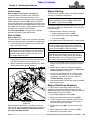
Control Panel
Figure 2-2
IMPORTANT: Always operate throttle at full engine
rpm while traveling or cutting grass. Operating
engine at a slow rpm may overheat engine and
hydraulic pumps.
23686
Engine Oil
Pressure Light
Ignition Switch
Hour Meter
Throttle
Blade
Engagement
Switch
Choke

14
Section 2: Operating Procedures
ZSR54, & ZSR60 Accu-Z Razor
®
Zero Turn Mowers 357-344M
Table of Contents
12/15/15
Choke
Refer to Figure 2-2 on page 13:
A cable is linked from the choke control knob to the
engine for choking the engine during starting. Pull up on
the knob to turn choke control knob (ON). Push down on
the knob once the engine is running to shut choke control
knob (OFF). Set choke control knob in the (OFF) position
soon after the engine has started.
Blade Engagement Switch
Refer to Figure 2-2 on page 13:
The blade engagement switch engages the deck blades.
Pull switch up (ON) to engage blades and push switch
down (OFF) to disengage blades.
Left/Right Fuel Tank Valve
Refer to Figure 2-3:
Located on the right side of the seat platform is the
Left/Right Fuel Tank Valve. It controls which fuel tank is in
use. The valve lever must be over one of the two arrows
to supply fuel to the engine. Arrows point to the fuel tank
being used. Switch fuel tank valve from one tank to the
other when fuel in the fuel sight gauge is low. The mower
does not have to be turned off to make the switch. See
“Fuel System” on page 38 for more information.
Left/Right Fuel Tank Valve
Figure 2-3
IMPORTANT: DO NOT operate mower with choke
on..
IMPORTANT: With mower stopped and engine at
half throttle, engage cutting blades. Increase throttle
to full engine speed and then operate control levers
to move mower. Clutch, belts and/or deck may be
damaged if blades are engaged at full engine speed.
Left/Right
Fuel Tank Valve
Center Position “O”
as Shown is OFF
27766
Fuel Sight Gauge
(Typical for both tanks)
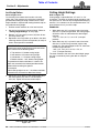
Park Brake
Refer to Figure 2-4 & Figure 2-5:
The park brake lever is linked to the wheel motors. The
rear wheels are kept from turning when the lever is pulled
up and back to (ON). Push the lever forward and down to
take the park brake (OFF).
Mower engine will stop running if the park brake is set to
(ON) before spreading both control levers (OUT) or if one
or both control levers are moved (IN) before moving the
park brake to (OFF).
Control Levers Fully OUT (in Park Position)
Figure 2-4
Control Levers Fully IN (In Neutral Position)
Figure 2-5
27765
Park Brake (ON)
Both Control Levers Should Be Spread Fully (OUT)
Before Park Brake Is Engaged (ON).
27820
Control Levers (IN)
Neutral Operating Position
Neutral Slot
Park Brake (OFF)

15
Section 2: Operating Procedures
ZSR54, & ZSR60 Accu-Z Razor
®
Zero Turn Mowers 357-344M
Table of Contents
12/15/15
Control Levers
Refer to Figure 2-4 & Figure 2-5 on page 14:
The control levers are used to steer, accelerate,
decelerate, stop, and change direction of travel.
Always move both control levers to neutral and (OUT)
before setting park brake to (ON). Always leave park
brake and control levers in this position until ready to start
traveling. Move park brake to (OFF) before pulling control
levers (IN). Start moving by moving control levers either
forward or rearward from neutral position.
See “Driving the Mower” on page 16 for a detailed
description of operating the control levers.
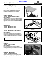
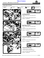
Deck Lift Pedal
Refer to Figure 2-6:
The deck lift pedal is used to raise and lower the mower
deck when setting the deck to the desired cutting height.
1. Push forward on deck lift pedal (#1) with your right
foot to raise deck fully up.
2. Use deck height indicator (#4) to locate desired
cutting height pin hole. Place deck height locking pin
(#2) into the selected cutting height pin hole.
3. With your right foot, release deck lift pedal (#1) slowly
to lower deck gently against locking pin.
.
Deck Lift Pedal
Figure 2-6
When going over obstructions, push deck lift pedal to
raise deck up. Go around obstruction if deck will not raise
high enough. Never mow over obstructions you are
not certain the deck will clear.
NOTE: Measurement provided on the deck height
indicator (#4) is with deck stop pin (#2) facing toward
stop handle (#5). If deck stop flat bar (#3) is facing
toward the stop handle as shown, add 1/4" to the
deck height dimension given.
27754
1
2
3
4
5
Engine Starting
The safety start interlock system is designed to prevent
runaway or accidental entanglement.
The following steps are correct procedures for starting
the engine. If difficulty is encountered, contact your local
Land Pride dealer.
1. Before starting the engine, make sure:
a. Blade engagement switch is (OFF).
b. Both control levers are positioned (OUT).
c. Park brake is (ON).
2. Set speed control to approximately 1/2 open throttle.
3. Insert key into ignition switch and rotate clockwise to
engage starting motor. Release key when engine
starts.
4. Perform test to make sure safety start interlock
system is operating properly. Refer to “Safety Start
Interlock System” on Page 16.
5. As soon as engine begins to run, check to make
certain oil warning light is off. If not, stop engine
immediately and check for the cause. Refer to
“Troubleshooting” on page 55.
6. Allow engine to idle a few minutes to warm up before
operating the mower.
Engine Shut-Down Sequence
It is always best to go through proper shut-down
sequence before turning ignition switch key off. Not
following this sequence in the correct order will cause the
engine to stop running immediately.
1. Shut blade engagement switch (OFF).
2. Move both control levers to neutral and (OUT).
3. Throttle engine back to a low idle and wait for one
minute to allow accumulated raw fuel to escape
muffler during engine slow down.
4. Position park brake (ON). (Pull up on lever until it
stops.)
5. Rotate ignition key counter-clockwise to (OFF).
6. Remove key from ignition switch.
IMPORTANT: The starter motor will engage only if
blade engagement switch is (OFF), control levers
are (OUT) , and park brake is (ON).
IMPORTANT: Use choke when engine is cold or if
warm and engine fails to start after 5 seconds of
cranking. Avoid engine flooding by pushing choke
control knob to (OFF) as soon as possible.
IMPORTANT: The engine starter should not be
operated for periods longer then 30 seconds at a
time. An interval of at least two minutes should be
allowed between such cranking periods to protect
the starter from overheating and burn-out.

16
Section 2: Operating Procedures
ZSR54, & ZSR60 Accu-Z Razor
®
Zero Turn Mowers 357-344M
Table of Contents
12/15/15
Safety Start Interlock System
The mower is equipped with a safety start interlock
system consisting of blade engagement switch, seat
switch, park brake switch, and control lever switches.
This system is an important safety feature designed to
prevent runaway or accidental entanglement.
The safety start interlock system should be checked daily
prior to operation and repaired immediately if it
malfunctions. Inspect system as follows:
1. Start mower engine per instructions in the section on
“Engine Starting” on page 15. Allow engine to warm
up to operating temperature.
2. With blade engagement switch (OFF), control levers
spread fully (OUT), and park brake (ON), slowly raise
off the seat. The engine should continue to run.
Blade Engagement Switch
1. With engine running and operator sitting on the seat,
move park brake to (OFF), pull both control levers
(IN), and then turn blade engagement switch (ON).
2. Replace blade engagement switch if blades did not
run and no other cause such as damaged wiring can
be determined.
Seat Switch
1. With conditions met in step 1 above, slowly raise off
the seat. The engine should stop within five seconds.
2. Replace seat safety switch if switch did not operate
properly and if no other cause can be determined.
Park Brake Switch
1. Turn blade engagement switch (OFF) and move
control levers (OUT). Park brake must be (OFF).
2. Try restarting the engine. The starter motor should
not turn.
3. Replace park brake switch if starter motor did turn
and if no other cause can be determined.
IMPORTANT: The starter motor will engage only if
blade engagement switch is (OFF), control levers
are (OUT), , and park brake is (ON).
Only after operator is seated and mower has been
started can park brake be moved to (OFF) and
control levers (IN) in that order or the engine will stop
running. The blade engagement switch can be pulled
(ON) only after both control levers are (IN).
Park brake positioned (ON) or (OFF) does not stop
engine when becoming unseated with both control
levers (OUT) and blade engagement switch (OFF).
IMPORTANT: The operator must be on the seat
when testing switches. Contact your local Land Pride
dealer if the problem cannot be resolved.
Control Lever Switches
1. With blade engagement switch (OFF), control levers
spread fully (OUT), and park brake (ON), restart
engine.
2. With park brake (ON) and blade engagement switch
(OFF), pull right control lever in. The engine should
stop within five seconds.
3. Replace right control lever switch if switch failed to
operate properly and if no other cause can be
determined.
4. Return control arm to original setting and restart
engine.
5. With park brake (ON) and blade engagement switch
(OFF), pull left control lever in. The engine should
stop within five seconds.
6. Replace left control lever switch if switch did not
operate properly and if no other cause can be
determined.
7. F o l l o w “Engine Shut-Down Sequence” on page 15
to turn off the mower.
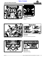
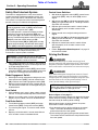
Driving the Mower
!
DANGER
Never make sudden stops or sudden reversing of travel
direction, especially when going down a slope. The steering is
designed for sensitive response. Rapid movement of control
levers could result in a reaction that can cause serious injury.
!
DANGER
Never make sudden speed changes from reverse to forward.
Always push control levers forward gently to avoid sudden
change in speed. Any sudden forward speed change can cause
the front wheels to raise off the ground resulting in loss of
control, mower damage and/or personal injury.
To Start and Increase Speed
Refer to Figure 2-7 on page 17:
After starting the engine, release park brake and engage
control levers by moving handles fully (IN). This makes
the levers ready for steering while traveling.
Moving control levers an equal distance away from
neutral will increase travel speed.
• Start forward travel by gently pushing on the control
levers. The further forward the control levers are
pushed the faster the travel speed.
• Start backing up by gently pulling on the control levers.
The further back the control levers are pulled the faster
the travel speed.
NOTE: When turning on soft wet turf, keep both
wheels rolling either forward or backward. Pivoting
on a stopped wheel can damage the turf.

17
Section 2: Operating Procedures
ZSR54, & ZSR60 Accu-Z Razor
®
Zero Turn Mowers 357-344M
Table of Contents
12/15/15
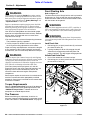
To Decrease Speed and Stop
!
WARNING
In the event of a system shutdown while mowing, move control
levers to neutral, and spread them fully apart. Also, engage
the park brake lever to aid in slowing and stopping the mower.
Refer to Figure 2-7 on page 17:
Moving control levers an equal distance towards neutral
will decrease travel speed.
• When moving forward, pull back gently on control
levers to decrease speed. The further back the control
levers are pulled the slower the travel speed until
neutral is reached.
• When backing up, push forward gently on control
levers to decrease speed. The further forward the
control levers are pushed the slower the travel speed
until neutral is reached.
• Move control levers to neutral to stop. (Ref. Frame #2)
• Spread both control levers fully apart and engage the
park brake. (Ref. Frame #1)
To Steer
Refer to Figure 2-7 on page 17:
• To Steer Straight While Traveling Forward
(Ref. Frame #3):
Push control levers forward an equal distance.
• To Steer Straight While Backing Up (Ref. Frame #4):
Pull control levers rearward an equal distance.
• To Turn Left While Traveling Forward (Ref. Frame #5):
Move right control lever farther forward from neutral
than the left control lever.
• To Turn Left While Backing Up (Ref. Frame #6):
Move right control lever farther back from neutral
than the left control lever.
• To Turn Right While Traveling Forward:
Move left control lever farther forward from neutral
than the right control lever.
• To Turn Right While Backing Up:
Move left control lever farther back from neutral than
the right control lever.
• To Make A Pivot Turn (Ref. Frame #7):
Move one control lever forward and the other control
lever back of neutral, this will allow the drive wheels
to counter-rotate.
Figure 2-7
Front of Mower Faces This Direction
25880
1 2
3
6 74 5

18
Section 2: Operating Procedures
ZSR54, & ZSR60 Accu-Z Razor
®
Zero Turn Mowers 357-344M
Table of Contents
12/15/15
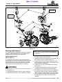
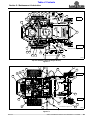
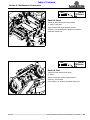
Accessing Area Beneath the Seat
Refer to Figure 2-8:
The compartment below the seat platform (#1) is where
the battery, control lever linkages, hydrostatic drives,
belts, and fuses are located. The seat is secured over this
compartment with a spring loaded latch. A carriage bolt
and nut is attached to the latch to meet safety
requirements.
!
WARNING
The seat pan should always be latched in the down position
and secured with bolt and nut before starting mower. Not
securing seat pan properly can cause bodily injury.
1. Park unit on a flat level surface. Stop engine and
remove ignition key. Make sure blade engagement
switch is in the down (OFF) position. Spread
control levers fully apart.
2. Remove hex flange nut (#4) and carriage bolt (#3)
from seat release latch (#2).
3. Pull latch arm (#2) to the left & lift seat platform (#1)
up to raise seat up and view compartment below.
4. When ready to close seat platform, lower platform
down until latch arm catches on the seat platform.
Insert 1/4" carriage bolt in the latch arm and secure
with hex flange nut (#4). See Seat Adjustment on
page 24 for positioning seat forward and rearward.
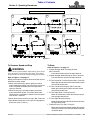
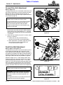
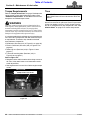
Moving Mower with Stalled Engine
Refer to Figure 2-9:
Each hydro-drive is equipped with a bypass valve for the
purpose of moving the mower when the engine is
inoperable. Both bypass valve rods are located at the
rear of the engine platform.
1. Pull back and up on one of the bypass valve rod loop
ends. Continue to hold the loop end up against the
engine platform while releasing the rod, The
upturned ends on the loop should catch on the
platform locking the transaxle in free wheeling.
2. Repeat step 1 for the other bypass valve rod and
transaxle.
3. Position both control levers in neutral with handles
fully apart.
4. Release park brake lever.
5. Manually move mower by hand or with a winch.
IMPORTANT: Do not tow mower. Move it by hand or
use a winch and load it onto a trailer. Make certain
mower is properly secured to the trailer and its park
brake is locked.
IMPORTANT: Following repairs, always make
certain the two bypass valve rods are returned to
their operating position.
Seat Release Latch
(Engine Not Shown For clarity)
Figure 2-8
Bypass Valve Rods (Operating Position Shown)
Figure 2-9
27770
27767
Bypass Valve Rods
Page is loading ...
Page is loading ...
Page is loading ...
Page is loading ...
Page is loading ...
Page is loading ...
Page is loading ...
Page is loading ...
Page is loading ...
Page is loading ...
Page is loading ...
Page is loading ...
Page is loading ...
Page is loading ...
Page is loading ...
Page is loading ...
Page is loading ...
Page is loading ...
Page is loading ...
Page is loading ...
Page is loading ...
Page is loading ...
Page is loading ...
Page is loading ...
Page is loading ...
Page is loading ...
Page is loading ...
Page is loading ...
Page is loading ...
Page is loading ...
Page is loading ...
Page is loading ...
Page is loading ...
Page is loading ...
Page is loading ...
Page is loading ...
Page is loading ...
Page is loading ...
Page is loading ...
Page is loading ...
Page is loading ...
Page is loading ...
-
 1
1
-
 2
2
-
 3
3
-
 4
4
-
 5
5
-
 6
6
-
 7
7
-
 8
8
-
 9
9
-
 10
10
-
 11
11
-
 12
12
-
 13
13
-
 14
14
-
 15
15
-
 16
16
-
 17
17
-
 18
18
-
 19
19
-
 20
20
-
 21
21
-
 22
22
-
 23
23
-
 24
24
-
 25
25
-
 26
26
-
 27
27
-
 28
28
-
 29
29
-
 30
30
-
 31
31
-
 32
32
-
 33
33
-
 34
34
-
 35
35
-
 36
36
-
 37
37
-
 38
38
-
 39
39
-
 40
40
-
 41
41
-
 42
42
-
 43
43
-
 44
44
-
 45
45
-
 46
46
-
 47
47
-
 48
48
-
 49
49
-
 50
50
-
 51
51
-
 52
52
-
 53
53
-
 54
54
-
 55
55
-
 56
56
-
 57
57
-
 58
58
-
 59
59
-
 60
60
-
 61
61
-
 62
62


Land Pride Lawn Mower & ZSR60 User manual
- Category
- Lawnmowers
- Type
- User manual
Ask a question and I''ll find the answer in the document
Finding information in a document is now easier with AI
Related papers


Other documents
-
 TAFCO PRODUCTS TSRW1416 Installation guide
-
 Avsl MSK024 User manual
-
Toro Belt Guard Kit, Z Master Commercial 2000 Series Riding Mower Installation guide
-
-
 California Trimmer 4041500 Operating instructions
-
Ariens 991161 Installation guide
-
-
Greenworks CRZ426 User guide
-
Ridetech 11369570 Operating instructions
-


