Page is loading ...

MODEL RT2000 (X2)
AUTOMATED TELLER MACHINE
SITE PREPARATION / INSTALLATION GUIDE
TDN 07100-00097 Dec 11 2009
CORPORATE HEADQUARTERS
21405 B St.
Long Beach, MS 39560
Phone: (228) 575-3188
Fax: (228) 575-3200
© 2009 Triton. All Rights Reserved. TRITON logo is
a registered trademark of Triton Systems of Delaware.

2
MODEL RT2000 (X2) INSTALLATION GUIDE
WHAT’S IN THIS INSTALLATION GUIDE
SITE COMPLIANCE. States the customers responsibilities for ensuring all relevant regulations, codes,
and laws are adhered to for installing ATMs.
ATM ENVIRONMENTAL PRECAUTIONS CHECKLIST. Describes the general environmental precautions and
the ATM, ensure the environmental criteria listed in this checklist are met.
DIMENSIONS. Describes physical dimensions for the cabinet(s), control panel components, and signage.
¾Physical dimensions.
¾Service area dimensions.
¾Customer access dimensions
INSTALLATION. Describes site preparation for exterior wall or vestibule locations. Instructions provide
the physical dimensions of the cabinet and associated hardware items. Optional platforms (“plinths”)
available in 2 sizes expedite raising the unit, if needed: 3” [76mm] or 6” [152mm].
INTRODUCTION
POWER AND COMMUNICATION. Shows cable access area, power requirements, and powering-up the unit.
APPENDIX A. Software License Agreement / Compliance/Emissions statements
APPENDIX B. ATM Installation for Accessibility guidelines.
INSTALLING /CONNECTING THE REAR OPERATOR SERVICE PANEL (RSP). Describes how to install and
connect the RSP.
The Triton RT2000 is a self-serviced, weatherized terminal adaptable for any suitable exterior (or interior)
wall or vestibule location. The cabinet design allows installation for maximum wall thickness up to 11-1/2”
[279mm]. Built-in leveling feet and optional platforms (“plinths”) allow the unit to be raised to the desired
height of the wall opening. The following section provides the physical dimensions and requirements for
installing the RT2000 for your particular site location. To assist you in preparing your site, a check list is
provided of various procedures that should be carried out prior to the arrival of the ATM.
DOCUMENT UPDATES:
Dec 11 2009 Page 30-31 Added warning to install RSP properly

3
MODEL RT2000 (X2) INSTALLATION GUIDE
CONTENTS
SITE COMPLIANCE .........................................................................................................4
E
NVIRONMENTAL PRECAUTIONS .....................................................................................5
TEMPERATURE / POWER / RF INTERFERENCE REQUIREMENTS .........................................................................6
DIMENSIONS ...................................................................................................................7
WALL OPENING / TRIM DIMENSIONS ...........................................................................................................8
C
USTOMER ACCESS DIMENSIONS .................................................................................................................9
S
IDE / REAR VIEWS ..................................................................................................................................10
S
ERVICE AREA DIMENSIONS
PREFERRED SERVICE AREA COMFIGURATION ................................................................................................ 11
M
INIMUM SERVICE AREA CONFIGURATIONS .................................................................................................12
CABINET / TRIM INSTALLATION .....................................................................................13
BEFORE YOU START ..................................................................................................................................14
D
ETERMINE IF “PLINTH” REQUIRED ............................................................................................................15
T
OOLS / ITEMS REQUIRED .........................................................................................................................16
I
NSTALLATION OF CABINET .........................................................................................................................17
I
NSTALLING CONTROL PANEL TRIM HARDWARE ...........................................................................................21
S
EALING (WATERPROOFING) THE CONTROL PANEL TRIM HARDWARE .............................................................23
ROUTE POWER / COMMUNICATION CABLES ...................................................................25
ROUTE / CONNECT THE POWER AND PHONE (DIAL-UP) CABLES ...................................................................26
R
OUTE / CONNECT TCP/IP (ETHERNET) CABLE ..........................................................................................28
REAR SERVICE PANEL INSTALLATION ............................................................................29
REAR SERVICE PANEL INSTALL ...................................................................................................................30
S
ET JUMPER FOR REAR SERVICE PANEL ......................................................................................................31
TDM-SERIES CASSETTE INSTALLATION ........................................................................33
INSTALLING TDM CASSETTE(S) .................................................................................................................34
RECEIPT PAPER INSTALLATION ......................................................................................35
INSTALLING THE RECEIPT PAPER .................................................................................................................36
APPENDIX A - SOFTWARE LICENSE AGREEMENT / COMPLIANCE/EMISSIONS STATEMENTS
APPENDIX B - ATM INSTALLATION FOR ACCESSIBILITY

4
MODEL RT2000 (X2) INSTALLATION GUIDE
This document contains the information necessary for the preparation and installation of an RT2000 Triton
electrical wiring and mechanical systems must also comply with all relevant laws and regulations.
The site must be prepared by the customer or his agent who is fully conversant with the requirements of
installing ATM equipment. The responsibility for ensuring that the site is prepared in compliance with this
document remains with the customer.
For information and guidance only, a list is provided in general terms of those matters for which the cus-
the responsibility of the customer for all aspects of adequate site preparation.
1. Location of the equipment and site preparation.
2. Site wiring (power, communication).
3. Location of other equipment that may cause electrical, electromagnetic or heat induced interference.
4. Make building alterations to meet wiring and other site requirements.
5. Install all communication cables, wall jacks, and associated hardware.
6. Provide and install necessary power distribution boxes, conduits, and grounds.
7. Ensure all applicable codes, regulations, and laws (electrical, building, safety) are adhered to.
8. Ensure the environmental requirements of this unit are met.
9. Install the unit at a height which meets the ADA/DDA/CSA accessibility regulations for the state/
country installed.
SITE COMPLIANCE
SITE PREPARATION CHECKLIST

5
MODEL RT2000 (X2) INSTALLATION GUIDE
ENVIRONMENTAL PRECAUTION CHECKLIST

6
MODEL RT2000 (X2) INSTALLATION GUIDE
TEMPERATURE / HUMIDITY
1. The ATM will operate over a range of tem-
peratures and humidity. Generally, these
parameters must fall within the following
ranges:
DEDICATED TELEPHONE
3. Ensure the following telephone-line require-
ments are met:
Dedicated line. The telephone line servicing the
ATM will not be a “party” line or any other shared
type connection.
Proximity to Interference Sources. The tele-
phone line must not be in close proximity to “noisy”
devices that could induce interference into the ATM
communications channel. See the next section for
additional information on “interference sources.”
RF INTERFERENCE
4. Ensure there are no devices near the termi-
nal that may cause RF interference, such as:
TVs
Coolers
Security devices
Neon signs
Devices with compressors
* IMPORTANT *
AC power for the terminal should come from
a dedicated source with an isolated ground.
Dedicated source. The ATM AC power feed will be
a dedicated line, to which no other electrical devices
are connected. The ATM power line will be wired for
a single “duplex”-style outlet and connected directly
to the AC service panel.
Isolated Ground. An equipment grounding conduc-
tor that is insulated from the conduit or raceway and
all other grounding points throughout its entire length.
The only points of electrical connection will be at
the duplex outlet and service panel ends of the line.
AC POWER REQUIREMENTS
2. Ensure the following AC power requirements
are met:
Current (Max)
5.05A @ 115 VRMS at 60 Hz
2.01A @ 230 VRMS at 50 Hz
Voltage
Power Consumption (Idle)
Power Consumption (Max Load)
Temperature (Exterior)
Relative Humidity
When installing an ATM, some general environmental and power precautions need to be con-
sidered. Evaluate the location where the ATM will be installed. To help ensure proper operation
of the ATM, ensure the environmental criteria listed are met.
Temperature (Interior)
Relative Humidity

7
MODEL RT2000 (X2) INSTALLATION GUIDE
DIMENSIONS
Dimensions listed comply with US Federal ADA
Guidelines. For USA installations, check for
additional guidance. For non-USA installa-
tions, check regulations relating to the country
of install.
The maximum wall thickness is 11-1/2” (279
mm).
Note:
Dimensions shown in inches and [millimeters]

8
MODEL RT2000 (X2) INSTALLATION GUIDE
WALL OPENING / TRIM DIMENSIONS
*
-
-
**
Height
-
ance
-
ance
*
**
-
-
(Figure F
This area must be free of obstruction
for trim installation
Exterior ground
Exterior ground

9
MODEL RT2000 (X2) INSTALLATION GUIDE
CUSTOMER ACCESS DIMENSIONS
CABINET
“
FOOTPRINT”
Note: Front of unit.

10
MODEL RT2000 (X2) INSTALLATION GUIDE
SIDE VIEW
PHYSICAL DIMENSIONS
REAR VIEW
Note: Terminal shown with 6” plinth utilized.
Exterior ground
6” plinth
6” plinth
Interior

11
MODEL RT2000 (X2) INSTALLATION GUIDE
SERVICE AREA DIMENSIONS
Ensure that doorways and corridors leading to the point of installation are wide enough to allow the ship-
ping package to pass through. If access is restricted, make arrangements to unpack the unit in an area with
the unit. The service area dimensions and clearances recommended for the RT2000 cabinet installation.
PREFERRED SERVICE CONFIGURATION

12
MODEL RT2000 (X2) INSTALLATION GUIDE
MINIMUM SERVICE CONFIGURATIONS

13
MODEL RT2000 (X2) INSTALLATION GUIDE
INSTALLATION

14
MODEL RT2000 (X2) INSTALLATION GUIDE
BEFORE YOU START
securing the unit through the leveling feet “plinth” hardware, regardless of how high the unit may be raised.
Listed are some general considerations when securing the unit:
Â
Â
See next page for determining if a plinth is required.
ÂEnsure that doorways and corridors leading to the point of installation are wide enough to allow the
shipping package to pass through. If access is restricted, make arrangements to unpack the unit in an
ÂIf installing an RT2000 where a previous ATM was installed, verify that the wall opening is consistent
may be required.
Â
Â
Level 1 Cabinet Safety
cabinets! Exercise extreme caution
when moving Level 1 cabinets!
At least two persons should work
together to move the cabinet into
position for mounting!
Tool Use / Safety
Observe ALL safety precautions
for operating hand and power
-
tion while operating the electric
drill!
USE A BACK-SUPPORT BELT
WHEN LIFTING AND MOV-
ING THE ATM!

15
MODEL RT2000 (X2) INSTALLATION GUIDE
DETERMINE IF PLINTH REQUIRED
Triton Systems offers two (2) metal-constructed optional plinths w/leveling feet. A “plinth” is a platform on
which the ATM rests or is secured. A plinth enables the ATM to be installed at the required height through
the wall. The plinths come in 2 heights: 3” [76mm] and 6” [152 mm - shown below]. You can raise the
plinths leveling feet. Recommenda-
tion: When using the leveling feet, do not exceed 3/4”in adjustment. To determine if you need to order
a plinth with your unit, a few measurements will be needed at the site.
For sites that currently have a wall opening:
2. Cabinet dimensions are 28” from bottom of sleeve to base of cabinet (Figure 2).
3. Subtract the difference to determine if a plinth is needed or what height plinth to order or build. If
not
Figure 1. Determine height of opening
c
d
e
28”
(711mm)
Figure 2. Height of cabinet base
to bottom of sleeve (28”).
c Leveling feet
d Anchor holes
e Cabinet/Stack holes

16
MODEL RT2000 (X2) INSTALLATION GUIDE
TOOLS / ITEMS REQUIRED
Lifting/moving devices
(pallet jack, forklift, lifting jack/trolley, etc)
Crowbar / roll bars,
scrap lumber (blocking)
Tape measure / bubble level / framing square Hammer / chisel
Back support belt / safety goggles,/mask
steel-toed shoes
Marker / pencil
Tool kit consisting of:
Adjustable wrench (large), box wrenches (open / closed) - up to 1-1/4” (32 mm)
Water-resistant sealant (caulk, etc)
Torque wrench, adjustable to at least 60 foot pounds,
adjustable wrench, or ratchet wrench
Center punch (or equivalent) for marking drill points
Hammer 3/4” (19 mm) socket
Bubble level
7/16” (11 mm)
socket / box wrench
Safety goggles
Hearing protec-
tion
1/4” (6 mm) , 1/2” (12 mm),
and 9/16” (15 mm) carbide-
tipped masonry drill bits - at
least 6” (152 mm) long
3/4” (19 mm)
heavy -duty electric drill
(rotary/hammer)
Back support belt Portable vacuum cleaner Wire brush
1/2” (12 mm)
1/2” (12 mm) x 4-1/4” (107
mm) sleeve-type anchor bolts
1/2” (12 mm) nuts

17
MODEL RT2000 (X2) INSTALLATION GUIDE
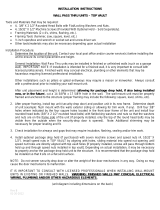
INSTALLING CABINET THROUGH WALL OPENING
1. Carefully inspect the unit for any shipping damage and report
any damage immediately to the shipping company. Refer to
the warranty information in the User manual for information
about reporting shipping damage.
2. After unpacking the unit, move the cabinet using the proper
lifting/moving device to the wall opening.
Slide unit up to interior wall.
*Important*
DO NOT install the control
panel fascia at this time.
3. Slide the unit up to the opening until the sleeve portion of the
cabinet is near the wall.
4. Measure the distance from the bottom of the wall opening to
the bottom of the sleeve. This will be the height requirement
of the “plinth”, if needed. Add an additional 1/2” (12 mm) to
your measurement for clearance
Note
A “plinth” is a platform on which the
ATM rests or is secured. This plinth
enables the ATM to be installed at
the required height through the wall.
5. If no plinth is required, slide the unit forward towards the wall
opening so the sleeve protrudes slightly out the front exterior
Minor adjustments for raising/leveling the unit can be made
using the cabinet leveling feet. Proceed to Step 8.
*** WARNING ***
The RT2000 unit is top heavy. USE EXTREME
CAUTION! Always move/support the unit from
the FRONT! 2-personnel are recommended when
unpacking and moving the unit!!
Measure from bottom of wall open-
ing to bottom of sleeve.

18
MODEL RT2000 (X2) INSTALLATION GUIDE
6. If a plinth is used (either built or purchased), mount the cabinet on the plinth. Anchor the cabinet to
the plinth using the bolts provided (optional plinth) or secure to your built plinth. Tighten bolts enough
to secure the two together for moving the unit.
7. Slide/move the unit forward towards the wall opening so the
sleeve protrudes slightly out the front exterior. This is needed to
raising the unit can be made using the plinths leveling feet (see
“Adjusting Height of Unit page 20).
8. Locate the control panel trim included with the unit accessories.
On the back side are four (4) clips that will align with four (4)
slots on the sleeve control panel.
9. Align the trim bracket clips with the sleeve slots and insert until
the trim is seated on the control panel. DO NOT secure the trim
at this time.
-
Sleeve protrudes slightly.
Control panel trim.
Trim clips.
**CAUTION**
When placing the unit on the plinth, be careful not to damage
the front of the sleeve as this has the control panel electronics
and hardware mounted.

19
MODEL RT2000 (X2) INSTALLATION GUIDE
10.
Control panel slots.
Mount fascia trim to control panel.
*** WARNING ***
When removing/placing the unit on the plinth, be
mindful that the unit is top-heavy. One person should
support the front at all times! Take care not to damage
the front of the sleeve as this has the control panel
electronics and hardware mounted.
11. Adjust the plinth’s
the cabinet is level.
12
tape, pencil, etc. Remove the control panel trim and slide the unit back inside.
13. Remove the unit from the plinth (if used). Align the plinth over the markings and mark the anchor holes.
used) and again slide the unit forward towards the wall opening until the sleeve protrudes slightly out
the front exterior.
If no plinth was used, after drilling the anchor holes, again slide the unit forward towards the wall
opening until the sleeve protrudes slightly out the front exterior.
The next pages describes adjusting the optional plinth and leveling feet of cabinet.

20
MODEL RT2000 (X2) INSTALLATION GUIDE
ADJUSTING HEIGHT/LEVEL OF UNIT
Triton Systems offers two (2) metal-constructed optional plinths w/leveling feet. The
plinths come in 2 heights: 3” (76 mm) and 6” (152 mm - shown below). Based on the
height requirement needed, you can either:
1) Raise the unit with the leveling feet installed in the cabinet (Business Hours
and Level 1) using a 1/4” (6mm) nut driver/socket.
(Caution: The leveling feet are primarily for that purpose - leveling the ATM, not to
raise the unit by more than 3/4”).
2) Construct your own plinth. A “plinth” is a platform on which the ATM rests or is
secured. This plinth enables the ATM to be installed at the required height through the
wall. If built, it must be no smaller than the base of the cabinet and must be constructed
of a material that is capable of supporting the weight of the ATM.
3)
needed, adjust up using the plinths leveling feet (adjustable crescent wrench required).
Caution: Leveling feet are primarily used for leveling the ATM, not to raise the unit
by more than 3/4”.
4) “Stack” the optional plinths. Before securing two (2) plinths together, remove the
leveling feet from the top plinth.
c Leveling feet
d Anchor holes
e Cabinet/Stack holes
c
d
e
/