Page is loading ...

www.mellanox.com
BridgeX
®
GT Series BX5020 Gateway IB to
Ethernet User Manual
P/N:
MBX5020-1SFR
Rev 1.4

Mellanox Technologies
350 Oakmead Parkway Suite 100
Sunnyvale, CA 94085
U.S.A.
www.mellanox.com
Tel: (408) 970-3400
Fax: (408) 970-3403
Mellanox Technologies, Ltd.
PO Box 586 Hermon Building
Yokneam 20692
Israel
Tel: +972-4-909-7200
Fax: +972-4-959-3245
© Copyright 2011. Mellanox Technologies. All rights reserved.
Mellanox®, BridgeX®, ConnectX®, CORE-Direct®, InfiniBlast®, InfiniBridge®, InfiniHost®, InfiniRISC®, InfiniScale®, InfiniPCI®,
PhyX®, Virtual Protocol Interconnect® and Voltaire® are registered trademarks of Mellanox Technologies, Ltd.
FabricIT™ and SwitchX™ are trademarks of Mellanox Technologies, Ltd.
BridgeX® BX5020 Gateway IB to Ethernet
Document Number: 3276
Rev 1.4
Mellanox Technologies
2
NOTE:
THIS HARDWARE, SOFTWARE OR TEST SUITE PRODUCT (“PRODUCT(S)”) AND ITS RELATED DOCUMENTATION ARE
PROVIDED BY MELLANOX TECHNOLOGIES “AS-IS” WITH ALL FAULTS OF ANY KIND AND SOLELY FOR THE PURPOSE
OF AIDING THE CUSTOMER IN TESTING APPLICATIONS THAT USE THE PRODUCTS IN DESIGNATED SOLUTIONS. THE
CUSTOMER'S MANUFACTURING TEST ENVIRONMENT HAS NOT MET THE STANDARDS SET BY MELLANOX
TECHNOLOGIES TO FULLY QUALIFY THE PRODUCT(S) AND/OR THE SYSTEM USING IT. THEREFORE, MELLANOX
TECHNOLOGIES CANNOT AND DOES NOT GUARANTEE OR WARRANT THAT THE PRODUCTS WILL OPERATE WITH THE
HIGHEST QUALITY. ANY EXPRESS OR IMPLIED WARRANTIES, INCLUDING, BUT NOT LIMITED TO, THE IMPLIED
WARRANTIES OF MERCHANTABILITY, FITNESS FOR A PARTICULAR PURPOSE AND NONINFRINGEMENT ARE
DISCLAIMED. IN NO EVENT SHALL MELLANOX BE LIABLE TO CUSTOMER OR ANY THIRD PARTIES FOR ANY DIRECT,
INDIRECT, SPECIAL, EXEMPLARY, OR CONSEQUENTIAL DAMAGES OF ANY KIND (INCLUDING, BUT NOT LIMITED TO,
PAYMENT FOR PROCUREMENT OF SUBSTITUTE GOODS OR SERVICES; LOSS OF USE, DATA, OR PROFITS; OR BUSINESS
INTERRUPTION) HOWEVER CAUSED AND ON ANY THEORY OF LIABILITY, WHETHER IN CONTRACT, STRICT LIABILITY,
OR TORT (INCLUDING NEGLIGENCE OR OTHERWISE) ARISING IN ANY WAY FROM THE USE OF THE PRODUCT(S) AND
RELATED DOCUMENTATION EVEN IF ADVISED OF THE POSSIBILITY OF SUCH DAMAGE.

Rev 1.4
Mellanox Technologies
3
Table of Contents
Table of Contents 3
List of Tables 5
List of Figures 6
Revision History 7
About this Manual 8
Intended Audience 8
Related Documentation 8
Conventions 8
Gateway Products Covered in this User Manual 9
Mellanox Part Numbering Legend 9
Chapter 1 Overview 10
1.1 Features 11
1.2 Serial Number and Product Version Information 12
1.3 Gateway Port Groups 12
Chapter 2 Installation and Basic Operation 14
2.1 Unpacking the Gateway 14
2.2 BridgeX Gateway Hardware Overview 14
2.2.1 Downlink Ports 14
2.2.2 Uplink Ports 15
2.2.3 Configuring the Port Gateway Groups 15
2.2.4 Making Connections to Other Formats 15
2.2.5 Status LEDs 16
2.2.6 Port Connector LEDs 19
2.2.7 Reset Button 19
2.2.8 Air Flow 20
2.2.9 Management Interfaces 21
2.3 Package Contents 22
2.4 Gateway Installation and Operation 22
2.4.1 Installation Safety Warnings 23
2.4.2 Mechanical Installation 26
2.4.3 Grounding the Gateway 30
2.4.4 Disassembling the Gateway from the Rack 30
2.4.5 Power Connections and Initial Power On 31
2.4.6 Shut Down Procedure 32
2.4.7 Extracting and Inserting the Power Supply Unit 32
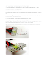
2.4.8 Cable Installation 33
2.4.9 Extracting and Inserting the Fan Unit 35
Chapter 3 Management and Software 37
3.1 FabricIT 37
Chapter 4 Troubleshooting 38
Appendix A Specifications 41
Appendix B EMC Certifications 43
B.1 EMC Certifications 43
Appendix C Interface Connector Pinouts 44
C.1 SFP+ Interface 44
C.2 RS232 to RJ45 Connector Interface 46

Rev 1.4
Mellanox Technologies
4
C.3 I2C RJ45 Connector Interface Pinout 47
C.4 QSFP Connector Pinout 48
Appendix D Replacement Parts Ordering Numbers 50
Appendix E Avertissements de sécurité d’installation (French) 52
Appendix F Installation - Sicherheitshinweise (German) 55
Appendix G Advertencias de seguridad para la instalación (Spanish) 58
Appendix H SFP+ Modules 62
H.1 Product Features 62
H.2 Applications 62
H.3 Dimensions 62
H.4 Pin Descriptions 63
H.5 Power Dissipation 64

Rev 1.4
Mellanox Technologies
5
List of Tables
Table 1: Revision History Table 7
Table 2: Reference Documents 8
Table 3: Gateway Products Covered by this User’s Manual 9
Table 4: Part Numbering Legend 9
Table 5: BX5020 Gateway Port Grouping, Protocols and Speeds 13
Table 6: System Status LED Configurations 17
Table 7: Fan LED Configurations 17
Table 8: PSU Status LED Configurations 18
Table 9: Port Connector LED Assignment 19
Table 10: Air Flow Direction 20
Table 11: Gateway and Installation Kit Options 26
Table 12: BX5020-1S Specification Data 41
Table 13: SFP+ Pinout 44
Table 14: Replacement Parts Ordering Numbers 50
Table 15: SFP+ Pinout 63

Rev 1.4
Mellanox Technologies
6
List of Figures
Figure 1: MBX 5020 Gateway 10
Figure 2: Port Numbering 11
Figure 3: Generic Product Label 12
Figure 4: Example of a Setup Showing a Port Group 13
Figure 5: Gateway System Connector and Power Side Panels 14
Figure 6: SFP+ Transceiver Module 15
Figure 7: Module with Locking Mechanism Closed 16
Figure 8: Module with Locking Mechanism Open 16
Figure 9: Power and System LEDs 16
Figure 10: BX Gateways Power Side Panel 18
Figure 11: Connector Port Identification 19
Figure 12: Reset Button 20
Figure 13: Management Interfaces 21
Figure 14: Installation Kit Parts 27
Figure 15: Making Room for the Power Cord 28
Figure 16: Screwing on the Bracket 28
Figure 17: Screwing on the Rail 28
Figure 18: Clipping in the Caged Nuts 29
Figure 19: Caged Nut Locations 29
Figure 20: Ground Connection 30
Figure 21: Two Power Inlets - Electric Caution Notifications 32
Figure 22: PSU Pulled Out 33
Figure 23: Top and Bottom Ports 34
Figure 24: Fan Unit Pulled Out 35
Figure 25: SFP+ Connector Pinout - Rear View of Module With Pin Placement 44
Figure 26: RJ45 Connector Pinout 46
Figure 27: I2C Pinouts 47
Figure 28: QSFP Connector Pinout 48
Figure 29: Pinout Looking Into the Rear of the Connector and the Front of the Cage 49
Figure 30: Rear View of Module With Pin Placement 63

Rev 1.4
Mellanox Technologies
7
Revision History
Table 1 - Revision History Table
Date Revision Description
August 2011 1.4 Updated Power numbers
Added Power as heat in BTUs/hr
June 2011 1.3 Removed references to FC
June 2011 1.2 Minor fixes
Feb. 2011 1.1 New power numbers
New I2C section
Sept. 2010 1.0 Initial release

Rev 1.4
Mellanox Technologies
8
About this Manual
This manual describes the installation and basic use of Mellanox BridgeX MBX5020 Gateway
products and development platforms based on the MT68102 BridgeX gateway device.
Intended Audience
This manual is intended for users and system administrators responsible for installing and setting
up BridgeX gateways from InfiniBand to Ethernet fabrics and networks.
The manual assumes familiarity with the InfiniBand
®
Architecture Specification as well as the
Ethernet Architecture.
Related Documentation
Additional documentation available from Mellanox is provided in Table 2.
Conventions
The terms uplink (internal) and downlink (external) are used throughout the document. Uplink
refers to the server switch facing ports, where InfiniBand (IB) is used. Downlink refers to the
Local Area Network (LAN) switch facing ports, where Ethernet (EN) are used.
Table 2 - Reference Documents
BridgeX Programmer’s Reference Manual
Document # 2936PM
User guide describing the interface used by developers to write a driver
between system software and the Mellanox BridgeX device.
FabricIT BX Management Software CLI
User’s Manual
User manual describing the software interface including examples for using
the BX manager and for installing EoIB and FCoE Host stacks.
www.mellanox.com > Products > Gateway Software > Software and Docu-
mentation Download.
You will need a valid Mellanox Gateway S/N.
Mellanox Firmware Tools (MFT) User’s
Manual
Document # 2329
The MFT (Mellanox Firmware Tools) package is a set of firmware tools. The
manual supplied with this package provides an overview of the firmware its
installation and replacement. The MFT can be downloaded with its documen-
tation at:
www.mellanox.com > Support > Download Firmware Tools
Caution: This symbol indicates the possibility of physical injury to the user or installer.

Rev 1.4
Mellanox Technologies
9
Gateway Products Covered in this User Manual
Mellanox Part Numbering Legend
Table 4 - Part Numbering Legend
This symbol indicates information that is helpful to the user.
Table 3 - Gateway Products Covered by this User’s Manual
Family Product Number Description
BridgeX IB Gateways
MBX5020
BridgeX IB system, dual controllers, 4 QSFP uplink ports and 16
SFP+ downlink ports with CPU, RoHS6
Place Field Decoder
M Mellanox Technologies
BX System Type = BridgeX based Bridge System
1 Gateway protocols 1 = Ethernet Uplinks
5 = InfiniBand Uplinks
9 = VPI (Ethernet and InfiniBand) Uplinks
0 For future use
2 # of BridgeX devices 1 = For future use
2 = 2 BridgeX devices
0 For future use
– Separator
1 # Power Supplies 1=1, 2=2
M Depth of the Unit S = standard depth, B = For future use
Y Air Flow direction R= connector (IB/ETH) side to PSU side airflow
F= PSU side to connector (IB/ETH) side airflow
R RoHS C=RoHS5, R=RoHS6

OverviewRev 1.4
Mellanox Technologies
10
1Overview
The Mellanox BridgeX gateway series is a 1U, top-of-rack gateway that provides server I/O con-
solidation over an InfiniBand network. The product supports 40Gb/s InfiniBand to 1GigE/10GigE
Ethernet bridging.
The BridgeX Gateway is a multi-protocol bridge that enables InfiniBand connectivity to native
Ethernet networks. The gateway implements stateless bridging protocols by encapsulating Ether-
net over InfiniBand (EoIB) acting as a packet relay, based on read-only context. Bridging with the
gateway requires the use of Mellanox ConnectX or ConnectX 2 adapters on the server to imple-
ment server side processing of EoIB protocols. EoIB capable ConnectX and ConnectX 2 adapters
present standard Ethernet (Sockets) software interfaces to server applications providing transpar-
ent connectivity for existing Enterprise Data Center (EDC) and High Performance Computing
(HPC) applications to Ethernet LAN. ConnectX and ConnectX 2 adapters also present a standard
InfiniBand (Verbs) software interface to server applications for Inter Process Communication
(IPC). This allows Ethernet and InfiniBand payloads to be carried over a common converged high
performance 40Gbps InfiniBand fabric without any changes to existing server applications. Data
on the converged fabric requiring access to Ethernet LAN is bridged by the gateway preserving
existing LAN investments and management practices.
The BridgeX gateway along with ConnectX and ConnectX 2 adapters converge different networks
onto a single fabric, reducing the number of adapters, cables and switch ports by a factor of three
and reducing capital expenditure. The high port density of the gateway, within a 1U form factor,
low power consumption, and ease of management also reduces operating expenses.
Figure 1: MBX 5020 Gateway
STATUS
PSU 1
PSU 2
FAN
RST
< A
< B
EN
FC
EN
FC
MGT CONSOLE
MBX5020
1
2345
< C
EN
FC
< D
EN
FC
1
2345
1
2345
1
2345
Mellanox
!
!
OK
OK
!
!
OK
!
OK
I2C
Port groups
Product version
information tab location

Rev 1.4
Mellanox Technologies
11
Figure 2: Port Numbering
1.1 Features
The BridgeX Gateway series has the following features:
Uplink ports
• 4 ports of 40/G InfiniBand QSFP
Downlink ports
• 12 ports of 1 GigE /10 GigE Ethernet
• Down link ports are configured in groups of 3
• Down link ports within a group must run the same protocol
• A down link port group running Ethernet must run the same speed on all ports within the group
(10Gbps or 1Gbps)
1024 virtual NICs per Ethernet port
Total of 16,000 MAC addresses
Ethernet ports
• IEEE 802.3ae 10Gigabit Ethernet support
• IEEE 802.3z Gigabit Ethernet
• IEEE 802.1D Spanning Tree
• IEEE 802.1p QoS / COS
• IEEE 802.1Q VLAN Tagging
• IEEE 802.1AB Link Layer Discovery *
• IEEE 802.3ad Link Aggregation with LACP *
• IEEE 802.3x Flow Control (Per Priority Flow Control)
• Virtual lanes support
• Jumbo Frames up to 9K support
* This feature will be available to customers in the near future.
Connectors and Cabling
• SFP+ connectors for downlink 10GigE ports
• Optical transceiver modules for SR and LR for Ethernet
• Optical modules for FC
A1
A2
A5A3 A4
B1
B2
B5B3 B4
C1
C2
C5C3 C4
D1
D2
D5D3 D4

OverviewRev 1.4
Mellanox Technologies
12
Indicators
• Per port status LEDs; Link Activity
• System status LEDs: system, fans, power supply
• Ethernet indicators for downlink port groups
Management Options
• 2 – 1000BASE-T Ethernet ports
Power Supply
• Dual redundant slots
• 1 PSU is required for device functioning
1.2 Serial Number and Product Version Information
The serial number and product version information are found on the label seen in the figure below.
The product version information tab location is on the connector (IB/ETH) side of the gateway on
the bottom right hand side. See Figure 3 on page 12 for a sample of the product label. See Figure 1
on page 10 for the product label tab location.
Figure 3: Generic Product Label
1.3 Gateway Port Groups
There are four gateway groups in the BX5020 identified as A, B, C and D. Each gateway group
consists of one QSFP uplink port and four SFP+ down link ports. Each gateway group can be inde-
pendently configured. Within each gateway group, the QSFP uplink ports can be either 10Gbps,
20Gbps, or 40Gbps InfiniBand and the SFP+ downlink ports can be either 1Gbps or 10Gbps
Ethernet.
S/N: MT9054X00012
P/N:MBX5020-1SFC
GUID: 0002C902002642 FC
REV: X1
Made in IL
MGT MAC
00:02:C9:112F:9A

Rev 1.4
Mellanox Technologies
13
Table 5 - BX5020 Gateway Port Grouping, Protocols and Speeds
Figure 4: Example of a Setup Showing a Port Group
10Gbps
1Gbps
10Gbps10Gbps unused
1Gbps1Gbps unused
1
2345
Uplink
Downlinks
EN
IB
EN
10/20/40 Gbps
Gateway Group A
Downlink
port
numbers
Uplink port
numbers
Port protocol
and speed
10Gbps
1Gbps
10Gbps10Gbps unused
1Gbps1Gbps unused
Uplink
Downlinks
EN
IB
EN
10/20/40 Gbps
Gateway Group B
10Gbps
1Gbps
10Gbps10Gbps unused
1Gbps1Gbps unused
Uplink
Do w nlin ks
EN
IB
EN
10/20/40 Gbps
Gateway Group C
10Gbps
1Gbps
10Gbps10Gbps unused
1Gbps1Gbps unused
Uplink
Do w nlin ks
EN
IB
EN
10/20/40 Gbps
Gateway Group D
1
23 4 5
1
23 4 5
1
23 4 5
STATUS
PSU 1
PSU 2
FAN
RST
< A < B < C
<D
EN
FC
EN
FC
EN
FC
EN
FC
MGT CONSOLE
MBX 502 0
B20
A20
1234
5
678
1 234
5
678
Uplink
Downlink
Gateway
0
24
25
26 27
28
21
2019 22 23
29
30
32
33
34
35
31
MTS3600
InfiniBand Switch
36
11 12 13 1487654321 9 10 18171615
1234
5
678
QSFP Cable
Ethernet
IB

Installation and Basic OperationRev 1.4
Mellanox Technologies
14
2 Installation and Basic Operation
2.1 Unpacking the Gateway
Before you install your new BX5020, unpack the system and check to make sure that all the parts
have been sent, check this against the parts list. Check the parts for visible damage that may have
occurred during shipping.
See the package contents in Section 2.3.
2.2 BridgeX Gateway Hardware Overview
The figures below show dual hot-swap power supplies, 1 I2C connector, various status LEDs, and
the hot-swap fan module on the power side. The RS232 CONSOLE, 2 Management GigE connec-
tors, one USB connector, and various status LEDs on the connector (IB/ETH) side.
Figure 5: Gateway System Connector and Power Side Panels
All connectivity is via the connector panel. All connectors can support active cables.
2.2.1 Downlink Ports
There are four downlink ports per gateway port group. These ports have SFP+ connectors that sup-
port both direct-attach copper cables and optical cables by using SR or LR modules.
When configured for Ethernet, only 3 of the 4 downlink ports per gateway group are used and all
downlink ports within the gateway group must have the same speed, that is, 1Gbps or 10Gbps. See
Table 5 for the port numbers of the active Ethernet ports.
If anything is damaged or missing, contact your customer representative
immediately.
STATUS
PSU 1
PSU 2
FAN
RST
< A
< B
EN
FC
EN
FC
MGT CONSOLE
MBX5020
1
2345
< C
EN
FC
< D
EN
FC
1
2345
1
2345
1
2345
Mellanox
!
!
OK
OK
!
!
OK
!
OK
I2C
Power Side
Connector (IB/ETH) Side

Rev 1.4
Mellanox Technologies
15
2.2.2 Uplink Ports
There is one uplink port per gateway port group. This port has a QSFP Connector. These connec-
tors have support for powered cables and media adapter circuits. All of the Uplink ports must be
InfiniBand.
2.2.3 Configuring the Port Gateway Groups
See the FabricIT BXM Management Software CLI User Manual for CLI commands to configure
the gateway. You can also configure the gateway using the WebUI.
2.2.4 Making Connections to Other Formats
Hybrid CX4 to QSFP cables are supported on the uplink side. SR and LR modules can be used on
the downlink side. The following downlink options are also supported.
• SFP+ modules for 1/10GbE
2.2.4.1 SFP+ Transceiver Module
The gateways are shipped without optical modules. Approved Mellanox modules must be pur-
chased from Mellanox. The OPNs for the approved Mellanox modules are MFM1T02A-SR and
MFM1T02A-LR. The figure below shows the Mellanox approved SFP+ module.
Figure 6: SFP+ Transceiver Module
2.2.4.2 Inserting the Optical Transceiver Module
To insert the module into the cage:
1. Open the module’s locking mechanism– see Figure 7 and Figure 8.
2. Make sure that the male connectors on the module will align with the female connectors
inside of the cage. Also check that there is no dirt or foreign matter in the module or in the
cage.
SR and LR modules not recommended by Mellanox may not work with the
adapter.

Installation and Basic OperationRev 1.4
Mellanox Technologies
16
Figure 7: Module with Locking Mechanism Closed
Figure 8: Module with Locking Mechanism Open
3. Insert the module into the adapter card module cage.
4. Close the locking Mechanism.
To remove the module from the cage:
1. Unlock the locking mechanism by opening the handle.
2. Pull the module out of the cage.
2.2.5 Status LEDs
Figure 9: Power and System LEDs
2.2.5.1 System Status Indicators
Status indicators are located on the right side of power side panel and on the left side of the con-
nector (IB/ETH) side panel. Both of these system status indicators are three color LEDs, display-
ing the same status on both sides of the gateway. The following status conditions are possible.
!
!
OK
OK
!
!
OK
STATUS
PSU 1
PSU 2
FAN
RST
System Status Indicators
PSU Status Indicators

Rev 1.4
Mellanox Technologies
17
2.2.5.2 Fan Status Indicators
The fan unit is located in the center of the power side panel. The fan unit has a single 2 color LED
to the right of the fan, that indicates the internal status of the unit.
An identical indicator labeled “Fans” is located on the left side of the connector (IB/ETH) side
panel. The following fan status conditions are possible:
Table 6 - System Status LED Configurations
LED Configuration STATUS/ System Health LED
Green OK – The system is up and running.
Yellow Error –A fault in the system, most likely the firmware did not BOOT properly.
Red Major Error –Possible damage can result to the gateway. Turn off immediately.
For example; bad FW, can’t boot, or overheated
Note: When the system is turned on, the red LED will light up for up to
two minutes, until the CPU is up and running.
Off Off – The system has no power.
If the STATUS LED shows red after five minutes unplug the gateway and call your
Mellanox representative for assistance.
If the FAN LED shows red, troubleshoot the fan module.
If the gateway shuts down due to over temperature, unplug the gateway, wait 5 minutes
and replug in the gateway.
Table 7 - Fan LED Configurations
LED Configuration Fan LED
Green OK – The system is up and running.
Red Error –One or more fans is not operating properly. The system should be
powered down and troubleshoot the fan module.
Off Off – The fan unit is not receiving any power. Check that the fan unit is
properly and completely inserted.

Installation and Basic OperationRev 1.4
Mellanox Technologies
18
2.2.5.3 Power Supply Status Indicators
The gateway is available with one or two factory installed Power Supply Units. For gateways with
only one unit installed, a second Power Supply Unit can be added to increase security, hot-swap
ability and to add redundancy. See Section E, “Replacement Parts Ordering Numbers,” on page 25
for ordering part numbers.
Figure 10: BX Gateways Power Side Panel
The primary power supply unit (PSU1) is located on the right side of the power side panel, with
PSU2 on the left side. Each PSU also has a single 2 color LED to the right of the PSU, that indi-
cates the internal status of the unit.
PSU status indicators are also located on the left side of the connector (IB/ETH) side panel, and
labeled “PSU1” and “PSU2”. Table 8 Shows the explanation of the PSU Status LED colors.
All fans must be operating while the power supply is plugged in.
If the gateway shuts down due to over temperature, unplug the gateway, wait 5 minutes
and replug in the gateway.
Table 8 - PSU Status LED Configurations
LED Configuration Fan LED
Green OK – The Power supply is delivering the correct voltage. 12VDC
Red Error – The PSU is not operational. Replace the PSU.
Mellanox
!
!
OK
OK
!
!
OK
!
OK
I2C
Fan unit
PSU 1
Primary Power Supply Unit
PSU 2
Secondary Power
Supply Unit
PSU LED
Fan LED
PSU LED

Rev 1.4
Mellanox Technologies
19
2.2.6 Port Connector LEDs
Figure 11: Connector Port Identification
Above the ports are two LEDs one for the upper port and one for the lower port . The fol-
lowing table shows the port status according to the LED indication.
2.2.7 Reset Button
On the connector (IB/ETH) side panel under the system LEDs is a reset button. This reset button
requires a tool to be pressed, a paper clip will do.
Off Off – There is no power to the system (neither PSU is receiving power). If one PSU is
showing green and the second PSU is unplugged it will show a red indication.
Table 9 - Port Connector LED Assignment
LED LED Description
Off No power to the port.
Solid Green Logical link up
Flashing Green Data activity
flashing speed ≈ data transfer speed
Orange Physical link up
Flashing Orange A problem with the physical link
DO NOT use a sharp pointed object such as needle or push pin for pressing the Reset
button. Sharp objects can cause damage, use a flat object such as a paper clip.
Table 8 - PSU Status LED Configurations
LED Configuration Fan LED
STATUS
PSU 1
PSU 2
FAN
RST
< A
< B
EN
FC
EN
FC
MGT CONSOLE
MBX5020
1
2345
< C
EN
FC
< D
EN
FC
1
2345
1
2345
1
2345
Port group labels
Port numbers

Installation and Basic OperationRev 1.4
Mellanox Technologies
20
Figure 12: Reset Button
This button resets both the CPU of the gateway device and the CPU of the management module. It
thereby resets all of the ports by bringing them down and powering them up when the button is
pushed. A quick push of this button performs this reset. When the button is held down for 5 sec-
onds the gateway is reset and the password is changed back to the default password “admin”.
2.2.8 Air Flow
These gateways can come with two air flow patterns. The two patterns are
• connector (IB/ETH) side inlet to power side outlet
• Power side inlet to connector (IB/ETH) side outlet
The air flow is specified in the product model number. See “Mellanox Part Numbering Legend” on
page 9. On the PSUs and fan modules the air flow direction can be seen on the power side panel.
Table 10 - Air Flow Direction
Picture OPN Designation Description
R
connector (IB/ETH) side inlet to power
side outlet
STATUS
PSU 1
PSU 2
FAN
RST
1
2
Reset button to reset the main and manage-
ment CPUs and to reset the existing password
back to the default. The password is returned
to the default password “admin”.
/