Page is loading ...

www.mellanox.com
648 Port InfiniBand QDR Switch Platform
Installation Guide
PN: MIS5600Q-10DNC
Rev 2.1

Mellanox Technologies
350 Oakmead Parkway Suite 100
Sunnyvale, CA 94085
U.S.A.
www.mellanox.com
Tel: (408) 970-3400
Fax: (408) 970-3403
Mellanox Technologies, Ltd.
PO Box 586 Hermon Building
Yokneam 20692
Israel
Tel: +972-4-909-7200
Fax: +972-4-959-3245
© Copyright 2011. Mellanox Technologies. All rights reserved.
Mellanox®, BridgeX®, ConnectX®, CORE-Direct®, InfiniBridge®, InfiniHost®, InfiniScale®, PhyX®, Virtual Protocol Interconnect and
Voltaire are registered trademarks of Mellanox Technologies, Ltd.
FabricIT, MLNX-OS and SwitchX are trademarks of Mellanox Technologies, Ltd.
All other trademarks are property of their respective owners.
648 Port InfiniBand QDR Switch Platform Installation Guide
Document Number: 3173
Rev 2.1
Mellanox Technologies
2
NOTE:
THIS HARDWARE, SOFTWARE OR TEST SUITE PRODUCT (“PRODUCT(S)”) AND ITS RELATED DOCUMENTATION ARE
PROVIDED BY MELLANOX TECHNOLOGIES “AS-IS” WITH ALL FAULTS OF ANY KIND AND SOLELY FOR THE PURPOSE
OF AIDING THE CUSTOMER IN TESTING APPLICATIONS THAT USE THE PRODUCTS IN DESIGNATED SOLUTIONS. THE
CUSTOMER'S MANUFACTURING TEST ENVIRONMENT HAS NOT MET THE STANDARDS SET BY MELLANOX
TECHNOLOGIES TO FULLY QUALIFY THE PRODUCTO(S) AND/OR THE SYSTEM USING IT. THEREFORE, MELLANOX
TECHNOLOGIES CANNOT AND DOES NOT GUARANTEE OR WARRANT THAT THE PRODUCTS WILL OPERATE WITH THE
HIGHEST QUALITY. ANY EXPRESS OR IMPLIED WARRANTIES, INCLUDING, BUT NOT LIMITED TO, THE IMPLIED
WARRANTIES OF MERCHANTABILITY, FITNESS FOR A PARTICULAR PURPOSE AND NONINFRINGEMENT ARE
DISCLAIMED. IN NO EVENT SHALL MELLANOX BE LIABLE TO CUSTOMER OR ANY THIRD PARTIES FOR ANY DIRECT,
INDIRECT, SPECIAL, EXEMPLARY, OR CONSEQUENTIAL DAMAGES OF ANY KIND (INCLUDING, BUT NOT LIMITED TO,
PAYMENT FOR PROCUREMENT OF SUBSTITUTE GOODS OR SERVICES; LOSS OF USE, DATA, OR PROFITS; OR BUSINESS
INTERRUPTION) HOWEVER CAUSED AND ON ANY THEORY OF LIABILITY, WHETHER IN CONTRACT, STRICT LIABILITY,
OR TORT (INCLUDING NEGLIGENCE OR OTHERWISE) ARISING IN ANY WAY FROM THE USE OF THE PRODUCT(S) AND
RELATED DOCUMENTATION EVEN IF ADVISED OF THE POSSIBILITY OF SUCH DAMAGE.

648 Port InfiniBand QDR Switch Platform User Manual
Rev 2.1
Mellanox Technologies 3
Table of Contents
Chapter 1 Chassis Installation 10
1.1 Environmental and Safety Recommendations 10
1.2 Chassis Package Contents 11
1.3 Leaf Package Contents 12
1.4 Spine Package Contents 12
1.5 Management Package Contents 12
1.6 Physical Installation 12
1.6.1 Starting with the Rack 13
1.6.2 ESD Connection 14
1.6.3 Installation Procedure 14
1.6.4 Installing the Cable Holder 32
1.7 Installing the Leafs 33
1.8 Inserting a Management Module 33
1.9 Inserting a Spine Board 34
Chapter 2 Installing the Cable Holder 36
Chapter 3 Ground Connections 38
Chapter 4 Power Connections 39
4.1 Powering Up the Switch Platform 39
Chapter 5 InfiniBand QSFP Cable Installation 41
5.1 Cable Power Classes 42
Chapter 6 Chassis Power Up 43
6.1 Power Supply, Management Board, and Spine Board Indicator Status at Power ON 44
Chapter 7 InfiniBand Fabric Initialization and Management 45
7.1 Configuring the Switch Management Modules for the First Time 45
7.2 Rerunning the Wizard 52
Chapter 8 Fabric Management Software 54
8.1 Downloading FabricIT Software and Documents 54
8.2 Installing Licenses 54
8.3 Getting and Inserting the License Key 54
8.4 FabricIT Management and Inspection License 57
8.5 Starting an SSH Connection to the Switch 57
8.6 Starting a WebUI Connection to the Switch 57
Chapter 9 Resetting the Switch – RST 59

Rev 2.1
Mellanox Technologies
4
List of Figures
Figure 1: Distance Between the Vertical Supports 13
Figure 2: Installation Kit Parts 16
Figure 3: Container Screws 17
Figure 4: Vertical Rack Supports Dimension 19
Figure 5: Adjustable Shelf Brackets 19
Figure 6: Placing the Shelf Bracket 20
Figure 7: Caged Nut Locations for the Shelf Brackets 21
Figure 8: Shelf Brackets 22
Figure 9: Place the Lock-Down Bar on the Shelf 22
Figure 10: U Numbering Above Shelf 23
Figure 11: Putting the Chassis in the Rack 24
Figure 12: Location for the Lock-down Bar 24
Figure 13: Place the Upper Bracket Offset 25
Figure 14: Attach the Shelf Extension 25
Figure 15: Place Caged Nuts 26
Figure 16: Fork Lift 27
Figure 17: Face Plate Mounting Bolt Locations 28
Figure 18: Upper Brackets and Offset Location 29
Figure 19: Upper Bracket Installation 29
Figure 20: Offset to Upper bracket Bolts 30
Figure 21: Lock-Down Bar 30
Figure 22: Bolt and Washer Order 31
Figure 23: Cable Holder 32
Figure 24: Ejector Latch 33
Figure 25: Ejector Latch 34
Figure 26: Management Module 34
Figure 27: Ejector Latch 35
Figure 28: Spine Board Insertion 35
Figure 29: Cable Holders 36
Figure 30: Ground Connection 38
Figure 31: Multiple Power Inlets - Electric Caution Notification 40
Figure 32: Spine Module 40
Figure 33: Top and Bottom Ports 41
Figure 34: Spine Side Panel Display Status Indications 44
Figure 35: Management Module Status Indications for Normal Operation 44
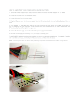
Figure 36: Connecting the Harness to the Console 45
Figure 37: License Key Entitlement Number 55

648 Port InfiniBand QDR Switch Platform User Manual
Rev 2.1
Mellanox Technologies 5
Figure 38: License Key Generation Form 55
Figure 39: FabricIT Status/Licensing 56
Figure 40: Web UI Login Page 58
Figure 41: Reset Button 59

Rev 2.1
Mellanox Technologies
6
List of Tables
Table 1: Revision History of this Installation Guide 7
Table 2: Reference Documents and Web Sites 8
Table 3: Serial Terminal Program Configuration 46
Table 4: Configuration Wizard Session - IP Configuration by DHCP 46
Table 5: Configuration Wizard Session - IP Zeroconf Configuration 48
Table 6: Configuration Wizard Session - Static IP Configuration 49

648 Port InfiniBand QDR Switch Platform User Manual
Rev 2.1
Mellanox Technologies 7
Revision History
Table 1 - Revision History of this Installation Guide
Revision Date Details
2.1 July 2011 Changes to Reset button section
2.0 June 2011 Changes to Installation kit
1.9 Nov. 2010 Changed cable guide graphic
1.8 Oct. 2010 Added air flow direction
1.7 Oct. 2010 Added step screw in bolts from offset to upper bracket.
1.6 Aug. 2010 Added weight lifting warning
Added “Remove all protective plastic film from all sides and top of the chas-
sis.”
Added cable power classes
1.5.3 July 2010 Added last page with barcode
1.5.2 June 2010 Added Note regarding initial configuration of the master and slave MMs
Added note regarding configuring the Box IP (BIP)
1.5.1 June 2010 minor fixes
1.5 June 2010 Changed order of Revision History and About
Added TOC, LOF, LOT and Heading1NoNumber to TOC
Synced this doc installation procedure with the UM
Added Getting and Inserting the License section
1.4 May 2010 Added notes for Hotswap
Added note for EFM upgrade
Turned the file into a book with FP, TOC...
Added getting the license section
1.3 April 2010 Reworked the Installation kit
1.2 April 2010 Power numbers
1.1 Jan. 2010 Formatting
1.0 Dec. 2009 Initial release

Rev 2.1
Mellanox Technologies
8
About this Manual
This manual provides installation and set-up instructions for the IS5600SX GT series QSFP Chas-
sis InfiniBand Switch Platform.
Intended Audience
This manual is intended for users and system administrators responsible for installing and setting
up the switch platform.
The manual assumes familiarity with the InfiniBand
®
architecture specification.
Related Documentation
The documentation set accompanying the QSFP Chassis InfiniBand Switch platform includes the
following:
Table 2 - Reference Documents and Web Sites
Document Conventions
Throughout this manual, the name and the term switch are used to describe the switch, unless
explicitly indicated otherwise.
The following pictures are used throughout this document to indicate information that is important
to the user.
Switch Firmware and Firmware Update Tools See
http://www.mellanox.com/content/
pages.php?pg=management_tools&menu_section=34
Note that the Switch System described in this manual is based on
Mellanox Technologies’ InfiniScale
®
IV switch device.
FabricIT
TM
Enterprise Fabric Management
(EFM) Software User’s Manual
Talk to your Mellanox representative for information regarding
licensing and implementation of the FabricIT Enterprise Fabric
Management Software System.
This symbol makes recommendations to the user.
This symbol indicates information that is helpful to the user.

648 Port InfiniBand QDR Switch Platform User Manual
Rev 2.1
Mellanox Technologies 9
This symbol indicates a situation that can potentially cause damage to hardware or
software.
BEWARE! This symbol indicates a situation that can potentially cause personal injury
or damage to hardware or software.

Chassis InstallationRev 2.1
Mellanox Technologies
10
1 Chassis Installation
Installation and initialization of the chassis is a simple process requiring attention to the normal
mechanical, power, and thermal precautions for rack-mounted equipment. Your Chassis will be
shipped in two packages one with the all of the leafs (leaf package) that are ordered and an extra
management module should it be ordered, and the second package (chassis package) with all of the
rest of the parts.
The chassis requires initial configuration to get the chassis and Fabric management up and running
through remote management.
1.1 Environmental and Safety Recommendations
The following are Mellanox recommendations.
This chassis can be installed in standard 19” racks that have depths between 65cm and
80cm between the vertical supports of the rack.
This unit is intended for installation in a Restricted Access Location. A restricted
access area can be accessed only through the use of a special tool, lock and key, or
other means of security.
Recommended ambient temperature in the System room is 20
o
± 5
o
C.
Recommended humidity ranges is 40% ± 15% without condensing.
It is highly recommended that the installation sites be as isolated as possible from all
sources of radio transmissions and electrical interference.
It is highly recommended that the installation site building be equipped with a light-
ning rod.

648 Port InfiniBand QDR Switch Platform User Manual
Rev 2.1
Mellanox Technologies 11
1.2 Chassis Package Contents
The package includes:
• 1 chassis with the following modules installed:
18 spines
1 management module
8 fans
10 PSUs
• 1 installation kit
• 1 box containing 10 power cords 125V 10A, C14 to C13, 6 feet long, USA UL Standard
• 1 cable management kit
• 1 installation guide (this document)
Before you install your new IS5600 series chassis, unpack the system and check to make
sure that all the parts have been sent, check this against the parts list. Check the parts for
visible damages that may have occurred during shipping.
It is highly recommended that the installation site be equipped with smoke detectors
and a fire alarm warning system.
The system requires a KVA rated UPS system. The heat dissipation is calculated
(Power Dissipation x 3.42 = Heat Dissipation). It is recommended that a UPS system
be installed to protect the equipment in the event of unexpected power failure.
A fully loaded IS5600 switch system can draw 8 kW (~67A @ 120V or 34A@240V)
of power. Make sure that the outlets and circuits will not be overloaded. Spread out the
load over at least two or three circuits or use a 3 phase circuit.
The leafs, spines, and management modules are shipped separately.
If anything is damaged or missing, contact your customer representative immediately.

Chassis InstallationRev 2.1
Mellanox Technologies
12
1.3 Leaf Package Contents
The package includes all of the leafs ordered by the customer.
1.4 Spine Package Contents
The package includes all of the spines ordered by the customer.
1.5 Management Package Contents
The package includes:
• all of the management modules ordered by the customer
• 1 RJ45 to DB9 harness
1.6 Physical Installation
The switch platform uses 31U of rack space in a standard 19” rack, 29U for the chassis and 2U for
the shelf. The switch ships from the factory with mounting holes on the spine side. There are upper
brackets to connect the leaf side to the rack near the top of the chassis, and there are two lock-
down bars to secure the chassis to the shelf. The weight of the switch is supported from underneath
the unit by the shelf.
This chassis can be installed in standard 19” racks that have depths between 65cm and 80cm
between the vertical supports of the rack. Make sure that a fully populated rack including cables
will have sufficient air flow for cooling.
The rack mounting holes conform to the IEA-310 standard for 19-inch racks. Guaran-
tee proper ventilation, by leaving 8cm (3”) of space to the front and rear of the switch.
This will ensure proper air flow through the chassis. This is crucial for maintaining
good airflow at ambient temperature. In particular, route cables such that they do not
impede the air into or out of the chassis.
Warning: This equipment is very heavy. Safety is the first concern. The fully loaded
chassis weighs
~740 lbs (~335 kg)
. Make sure that proper manpower and equipment
is used for transporting and moving the chassis.
Choose a rack which is able to support the mechanical and environmental characteris-
tics of a fully populated switch chassis.

648 Port InfiniBand QDR Switch Platform User Manual
Rev 2.1
Mellanox Technologies 13
1.6.1 Starting with the Rack
1.6.1.1 Rack Recommendation
1.6.1.2 Preparing the Rack
The rack may need to be modified to accommodate the 5600 chassis. The distance
between the vertical supports must be between 65 and 80 cm.
Figure 1: Distance Between the Vertical Supports
Due to the space required by up to 648 connector cables Mellanox recommends a rack
that is 120 cm long and 80cm wide. This will allow for proper cable management and
enough ventilation to properly cool the chassis.
Mellanox recommends that you remove both sides of the rack to make the installation
easier.
You will need a fork lift, to move and insert the chassis into the rack.
6
5
-
8
0
c
m
This edge of the shelf
must be as close as
possible to the inside of
the door when closed.

Chassis InstallationRev 2.1
Mellanox Technologies
14
The vertical supports may have to be moved so that the vertical support closest to the door is 6 cm
from the inside of the door. This may be required so that the shelf does not protrude from the rack.
1.6.2 ESD Connection
Before starting any procedure on the 5600 series switch system:
1. Put an ESD prevention wrist strap on your wrist, and make sure there is good contact
between your body and the strap.
2. Plug the other end of the wrist strap to a valid ground. Make sure that this is a tight fit.
1.6.3 Installation Procedure
1.6.3.1 Requirements
You will need:
If you move the vertical supports make sure that you reinstall them vertically
plumb.
Installing the chassis will be a lot easier if you can remove the sides of the rack.
You will need a fork lift, to move and insert the chassis into the rack.
• #2 phillips screwdriver • #3 phillips screwdriver
• a fork lift • a grounding lug
• measuring tape • ground wire of sufficient length and gauge to properly ground the
chassis
• One 9/16 box wrench
The installation will be much easier with a power screwdriver.
It is recommended to use AWG6 or 4mm diameter wire for grounding purposes.

648 Port InfiniBand QDR Switch Platform User Manual
Rev 2.1
Mellanox Technologies 15
• Parts included in the installation kit:
• Parts included in the cable management installation kit:
It is recommended to have at least two people for the duration of the installation proce-
dure. Use a mechanical lift to raise this chassis. If not, use enough manpower to ensure
the safety and wellbeing of all of the people involved in the installation.
- 1 shelf with brackets pre-installed - 1 shelf extension
- 1 left side upper bracket offset - 1 right side upper bracket offset
- 2 lock down bars - 2 upper bracket washers
- 8 lock washers for the upper brackets to verti-
cal support
- 12 lock washers for the upper brackets to
upper bracket offsets
- 12 hex head bolts – 8 for the upper
brackets and 4 for the shelf extension
- 34 caged nuts 20 for the shelf and 14 for the
chassis faceplate
- 34 pan head screws for the caged nuts 20 for
the shelf and 14 for the chassis faceplate
- 20 flat washers– 8 for the lock down bars
and 12 for the upper brackets
- 32 lock washers – 20 for the lock down bars
and 12 for the upper brackets to upper bracket
offsets
- 32 hex head bolts – 20 for the lock down
bars and 12 for the upper brackets to upper
bracket offsets
- 2 upper brackets - 12 flat head screws with locktite for the
upper bracket offsets
- 1 open end ratchet wrench 10mm - 1 socket nut driver 8mm
- 1 socket wrench - 1 socket nut driver 10mm
- 2 extensions for the socket driver - 1 socket nut driver 13mm
- 4 flat washers for the shelf extension
- 1 cable management rack RH - 1 cable management rack LH
- 16 caged nuts M6 - 16 M6 bolts

Chassis InstallationRev 2.1
Mellanox Technologies
16
Figure 2: Installation Kit Parts
1.6.3.2 Opening the Container
1. Before starting the procedure, put the ESD strap on and connect it to a valid ground.
2. Remove the four sides of the container by unscrewing the phillips head screws holding the
sides on.
Shelf
Caged nuts
Upper bracket
Lock washers
X8
#6 hex head bolt
Phillips pan head
screw
Upper bracket offset
Upper bracket Washer
Shelf extension
Lock-down bar
Flat washers
#8 hex head bolt
Flat washers
Flat head screws with
locktite
Lock washers
X6

648 Port InfiniBand QDR Switch Platform User Manual
Rev 2.1
Mellanox Technologies 17
Figure 3: Container Screws
3. Remove and put aside the box containing the cables.
4. Remove and put aside the box containing the cable management kit.
5. Remove and put aside the box containing the Installation kit.
6. Visually inspect the chassis, make sure that:
there is no visible damage
all 18 spines are installed
10 PSUs are installed
all 8 fans are installed
1 management module is installed
7. Remove all protective plastic film from all sides and top of the chassis.
The leafs, spines, and management modules are shipped separately.
Do not remove any of the blocks or either of the lock-down bars at this time.
Container screws

Chassis InstallationRev 2.1
Mellanox Technologies
18
1.6.3.3 Installing the Shelf
1. Select the location in the rack. Try to keep the chassis as low as possible to keep the center of
gravity low.
The maximum height that the chassis can be mounted, will be determined by the maximum height
that the fork lift can raise the pallet.
2. Open the Installation kit and make sure that all of the parts are in the box. See
Figure 2,“Installation Kit Parts”.
The chassis will sit in the rack with the spine side as close as possible to the door.
3. Measure the distance between the vertical supports and adjust the shelf bracket according to
this distance. This chassis can be installed a rack with a distance between the vertical sup
-
ports of from 65cm(25.6in.) to 80cm(31.5in.).
The chassis is on ball bearings and can roll easily. Be aware that the chassis can roll off
of the pallet. Should the chassis start to fall, move out of the way. The chassis can
cause grave bodily harm should it fall on or near you.
It is recommended to set the shelf at U5. Try and keep the chassis as low as possible.
The side of the chassis with the spine units will sit flush with the vertical supports of
the rack. The side of the chassis with the QSFP connectors will sit at the edge of the
shelf closer to the center of the rack.

648 Port InfiniBand QDR Switch Platform User Manual
Rev 2.1
Mellanox Technologies 19
Figure 4: Vertical Rack Supports Dimension
4. The shelf comes with the four brackets pre installed. Two of the brackets should be
loose. They may need to be removed and repositioned to meet the distance between
the vertical supports of the rack.
Figure 5: Adjustable Shelf Brackets
5. Move the shelf brackets on the shelf. Place the shelf bracket so that it measures
slightly more than the measured distance between the vertical rack supports. Make
6
5
-
8
0
c
m
These two brackets will
need to be adjusted. They
may even need to be
removed and repositioned.
The holes in the bracket are
offset to one side.
The holes must be closer to
the top of the shelf.

Chassis InstallationRev 2.1
Mellanox Technologies
20
sure that there is enough play in the bracket so that it can move to the vertical support. Do
not tighten the hex head bolts.
Figure 6: Placing the Shelf Bracket
6. Insert five caged nuts into the rack for each of the four shelf brackets (the 2 brackets that are
adjustable and the 2 that are fixed). Make sure that the caged nuts are all at the same height
on the vertical supports. Do not use the top hole in the bracket.
You may need to remove the brackets and reinstall them.
T
h
i
s
d
i
s
t
a
n
c
e
s
h
o
u
l
d
b
e
t
h
e
s
l
i
g
h
t
l
y
l
a
r
g
e
r
t
h
a
n
t
h
e
m
e
a
s
u
r
e
d
d
i
s
t
a
n
c
e
b
e
t
w
e
e
n
t
h
e
r
a
c
k
v
e
r
t
i
c
a
l
s
u
p
p
o
r
t
s
.
Adjusting slots
/