Page is loading ...

Printed in U.S.A.
LBI-38973
SERVICE SECTION
FOR
MDX GE-MARC 800 MHz RADIO
TABLE OF CONTENTS
DESCRIPTION............................................................................................................................................................ 1
INITIAL ADJUSTMENT.............................................................................................................................. 1
RECEIVER ADJUSTMENT......................................................................................................................... 1
RE-INSTALLATION.................................................................................................................................... 1
PREVENTIVE MAINTENANCE............................................................................................................................... 1
CONNECTIONS ........................................................................................................................................... 1
ELECTRICAL SYSTEM............................................................................................................................... 1
MECHANICAL INSPECTION..................................................................................................................... 1
ANTENNA.................................................................................................................................................... 1
ALIGNMENT................................................................................................................................................ 1
FREQUENCY CHECK................................................................................................................................. 1
STATIC HANDLING PRECAUTIONS...................................................................................................................... 1
DISSASSEMBLY PROCEDURES............................................................................................................................. 2
TO REMOVE BOTTOM COVER................................................................................................................ 2
TO REMOVE TOP COVER ......................................................................................................................... 2
TO REMOVE RF BOARD............................................................................................................................ 2
TO REMOVE THE FRONT CAP ASSEMBLY........................................................................................... 2
TO REMOVE THE AUDIO AMPLIFIER BOARD..................................................................................... 2
TO REMOVE THE AUDIO BOARD........................................................................................................... 2
TO REMOVE LOGIC BOARD .................................................................................................................... 2
TO REMOVE THE PA BOARD................................................................................................................... 2
TO REMOVE THE DISPLAY BOARD....................................................................................................... 3
COMPONENT REPLACEMENT............................................................................................................................... 3
SURFACE MOUNTED COMPONENTS..................................................................................................... 3
To Remove Surface Mounted Components ............................................................................................ 3
To Replace Surface Mounted Components............................................................................................. 3
To Replace Surface Mounted Integrated Circuits................................................................................... 3
TROUBLESHOOTING PROCEDURES .................................................................................................................... 4
Power On Self Diagnostic....................................................................................................................... 4
SYMPTOMS AND CHECKS...................................................................................................................................... 4

LBI-38973 LBI-38973
1
Copyright © August 1993, Ericsson GE Mobile Communications Inc.
DESCRIPTION
This Service Section contains the information
necessary for aligning and troubleshooting the MDX GE-
MARC 800 MHz Mobile Radio. In addition, information
is provided for disassembling the radio and replacing
surface mount components.
INITIAL ADJUSTMENT
After the radio has been installed as described in the
Installation Manual, the following adjustments should be
made by a certified electronics technician.
TRANSMITTER ADJUSTMENT
The transmitter has been adjusted at the factory and
should require no readjustment. However, the antenna
length should be adjusted for optimum VSWR, and the
frequency and modulation measured and recorded for
future reference. For complete transmitter alignment,
refer to the Alignment Procedures.
RECEIVER ADJUSTMENT
No initial adjustments to the receiver are required.
Refer to the Receiver Alignment Procedure when service
is required.
RE-INSTALLATION
The radio is designed to operate in 12 volt, negative
ground vehicles only. If the mobile radio is moved to a
different vehicle, always check the battery polarity of the
new vehicle system.
PREVENTIVE MAINTENANCE
To ensure high operating efficiency and to prevent
mechanical and electrical failures from interrupting
system operations, routine checks should be made of all
mechanical and electrical parts at regular intervals.
Preventive maintenance should include the following
checks.
CONNECTIONS
Ground connections to the voltage source should be
periodically checked for tightness. Loose or poor
connections to the power source cause excessive voltage drops
and faulty operation. When ground connections are not made
directly to the battery, the connection from the battery to
vehicle chassis must be checked for low resistance. A high
resistance may cause excessive voltage drops and alternator
noise problems.
ELECTRICAL SYSTEM
Check the voltage regulator and alternator or generator
periodically to keep the electrical system within safe
operational limits. Overvoltage is indicated when the battery
loses water rapidly. Usage of 1 or 2 ounces of water per cell
per week is acceptable for batteries in continuous operation. A
weak battery often causes excessive noise or faulty operation.
MECHANICAL INSPECTION
Since mobile units are subject to constant shock and
vibration, check for loose plugs, nuts, screws and other parts to
make sure that nothing is working loose.
ANTENNA
The antenna, antenna base and all contacts should be kept
clean and free from dirt or corrosion. If the antenna or its base
should become coated or poorly grounded, loss of radiation
and a weak signal often results.
ALIGNMENT
The transmitter and receiver meter readings should be
checked periodically and the alignment optimized when
necessary. Refer to the Alignment Procedure.
FREQUENCY CHECK
Check transmitter frequency and deviation. Normally,
these checks are made when the unit is first placed in
operation, after the first six months, and once a year thereafter.
STATIC HANDLING PRECAUTIONS
This radio contains Metal Oxide Semiconductor (MOS)
devices that are vulnerable to damage from Electrostatic
Discharge (ESD). As a result, extra care must be taken when
handling or testing the devices, modules, or the assemblies in
which they are used.
TABLE OF CONTENTS
TEST PREPARATION ..................................................................................................................................................... 4
TEST MODE OPERATION ............................................................................................................................... 5
Channel Frequency Select............................................................................................................................. 5
Test Functions............................................................................................................................................... 5
TEST PROCEDURE......................................................................................................................................................... 6
TRANSMITTER VERIFICATION ............................................................................................................. 6
Transmitter Frequency.................................................................................................................................. 6
Transmit Power............................................................................................................................................. 6
Audio Modulation Limiting.......................................................................................................................... 6
Busy Tone and Channel Guard Check.......................................................................................................... 6
RECEIVER VERIFICATION............................................................................................................................. 6
SINAD.......................................................................................................................................................... 6
Audio Output................................................................................................................................................ 6
SERVICE AIDS................................................................................................................................................................. 6
ALIGNMENT PROCEDURE ........................................................................................................................................... 7
TRANSMITTER ALIGNMENT......................................................................................................................... 7
Frequency Set............................................................................................................................................... 7
Audio Modulation Set................................................................................................................................... 7
Transmitter Power Set .................................................................................................................................. 7
Channel Guard Check................................................................................................................................... 7
RECEIVER ALIGNMENT................................................................................................................................. 7
Frequency Set............................................................................................................................................... 7
IF Tuning...................................................................................................................................................... 7
Quadrature Detector Adjustment.................................................................................................................. 7
Receiver Audio Level................................................................................................................................... 7
Squelch Adjust.............................................................................................................................................. 7
POWER DISTRIBUTION .................................................................................................................................. 7
A+................................................................................................................................................................. 8
SW A+.......................................................................................................................................................... 8
RF Board ...................................................................................................................................................... 8
Logic Board.................................................................................................................................................. 8
Audio Board ................................................................................................................................................. 8
Front Cap Assembly (Display Board)........................................................................................................... 8
Audio Amplifier Board................................................................................................................................. 8
AUDIO SIGNAL FLOW..................................................................................................................................... 8
Transmitter Audio......................................................................................................................................... 8
Receiver Audio............................................................................................................................................. 8
LOGIC SIGNAL FLOW ..................................................................................................................................... 8
APPENDIX A - GE-MARC TONES................................................................................................................................. 8

LBI-38973 LBI-38973
2
To prevent damage from ESD, observe the following
precautions:
• Service the radio only at a static free work station or
on a grounded mat.
• Perform diagnostics to isolate a faulty assembly or
component. Do not use canned coolant for fault
isolation.
• Discharge static voltage from your body by wearing a
grounded antistatic wrist strap where possible.
Where ground straps cannot be used, touch a
grounded item prior to handling an open radio.
• Avoid touching any electrically conductive parts of
circuit modules with your hands. When you must
handle components, pick them up by the body and
avoid touching the leads.
• Do not remove static sensitive devices from their
protective packaging until you are ready to install
them. Ground the package, to dissipate any
accumulated charge, prior to removing the
component.
• Ground all electrically powered test equipment.
Ground test equipment leads prior to connecting to a
circuit and connect the ground lead prior to
connecting the test probe. Disconnect the probe
before removing the ground lead.
• When soldering, be sure the soldering iron is
grounded using a three prong cord connected to an
outlet with a known good earth ground.
• Use only metallized or ESD protective vacuum-type
desoldering tools.
NOTE
This symbol is used to identify circuitry
using Electrostatic sensitive devices. Be
sure to follow Static Handling Procedures
when working near these devices.
DISASSEMBLY PROCEDURES
Disassembly procedures are provided to completely
disassemble the radio. In general, reassembly is in the
reverse order. Included are procedures to remove the top
and bottom covers, RF board, Audio Board, Logic Board,
System Board, and Front Cap Assembly, including the
Audio Amplifier Board and Display Board. Refer to
Assembly Diagrams located in the Combination Manual
(LBI-38960) for this radio when assembling or
disassembling the radio or replacing component boards.
NOTE
Remove power from the radio before servicing.
TO REMOVE BOTTOM COVER
1. Remove the four screws securing the bottom cover to
the radio.
2. Gently lift the bottom cover from the radio.
TO REMOVE TOP COVER
1. Remove the bottom cover and slide the top cover up
out of the casting.
NOTE
When replacing the covers check to see that the "O"
ring gaskets are properly seated in the cover grooves.
Also make sure the cables are pressed down in the
inner wall slots so they will not be pinched during
reassembly.
TO REMOVE RF BOARD
l. Remove the top and bottom covers from the radio.
2. Pry off the friction fit covers covering the RF board.
3. Gently pry interconnect plug P702 from the logic and
RF boards using a small standard screwdriver.
4. Remove the two clips securing Q101 and U102 to
the frame (on top side of board).
5. Remove the two M3.5-0.6 x 20 TORX screws (#15
drive) securing PA module U101 to the frame.
6. Remove the six M3.5-0.6 x 8 TORX screws (#15
drive) from the bottom side of the board.
7. Disconnect wires attached to J704, J705 and cables going
to the PA Board.
8. Remove the six spring clips protruding through the RF
board from the bottom side.
9. Gently push the RF board out of the radio casting.
TO REMOVE THE FRONT CAP ASSEMBLY
l. Remove the top and bottom covers of the radio.
2. Remove the four TORX screws (#10 drive) from top and
bottom of the front cap assembly.
3. Gently pull the front cap assembly away from the radio.
4. Disconnect the ribbon cable from the rear of the assembly
and disconnect the speaker leads from the system board.
The front cap assembly can then be removed from the
radio.
NOTE
When replacing the front cap assembly on the radio casting
first check that the "O" ring gasket is seated in the casting
groove. Carefully press the front cap over the gasket
making sure the gasket remains in the groove. Reinstall the
4 TORX screws while applying pressure to seat the front
cap against the casting.
TO REMOVE AUDIO AMPLIFIER BOARD
1. Remove the top and bottom covers.
2. Remove the Front Cap assembly.
3. Remove the four M3.5-0.6 x 8 TORX screws (#15 drive)
securing the audio amplifier board to the radio casting.
4. Disconnect the interconnecting cable between the Audio
Amplifier Board and the System and Display Boards.
5. Lift the Audio Amplifier Board out of the Front Cap
assembly.
TO REMOVE THE AUDIO BOARD
1. Remove the top and bottom covers from the radio. Refer
to the disassembly procedures for each.
2. Pull out the black clip protruding through the Audio
Board that holds the Logic Board 5 volt regulator against
the casting.
3. Remove the four M3.5-0.6 x 8 TORX screws (#15 drive)
securing the Audio Board to the radio. Pry out the board
using a screwdriver in the hole that was occupied by the
clip.
TO REMOVE THE LOGIC BOARD
1. Remove the top cover, bottom cover, front cap assembly,
and the Audio Board, from the radio. Refer to the
disassembly procedures for each.
2. Remove interconnecting plug P702 from the RF and
Logic Boards on the bottom of the radio.
3. Remove the four (4) M3.5-0.6 x 8 TORX screws (#15
drive) securing the Logic Board to the radio frame.
4. Carefully work the Logic Board out of the radio, being
careful not to damage the plug going to the Front Cap
Assembly.
TO REMOVE SYSTEM BOARD
1. Remove radio bottom cover.
2. Disconnect the speaker leads from J904.
3. Disconnect the ribbon cable from J902.
4. Disconnect the option cable, if used.
5. Remove the three M3.5-0.6 x 8 TORX screws (#15
drive) securing the system board to the frame.
6. Carefully work the board out of the radio, unplugging it
from feed through assembly Z903.
TO REMOVE THE PA BOARD
1. Remove the top and bottom covers as instructed above.
2. Disconnect the cables to the RF Board.
3. Disconnect the cable at J151 on the PA Board.

LBI-38973 LBI-38973
3
4. Remove the two M2.5-0.45 TORX screws (#8 drive)
securing the PA transistor to the frame.
5. Remove the four M3.5-0.6 TORX screws (#15 drive)
securing the board to the frame. Carefully work the board
out of the radio, uplugging it from the feed through
assembly Z903.
TO REMOVE THE DISPLAY BOARD
1. Remove the top and bottom covers and Front Cap
Assembly as directed above.
NOTE
When installing the PA Board in the radio, tighten the
screws securing the board to the casting to 15 inch-pounds.
Then install the screws securing the transistor and torque to
4.5 inch-pounds.
2. Remove the seven (7) M3.5-0.6 x 8 TORX screws (#15
drive) from the rear of the Front Cap Assembly to remove
the two brackets and center of the Display Board.
3. Gently pull the control panel away from the front cap and
disconnect the ribbon cable on the rear of the panel.
COMPONENT REPLACEMENT
SURFACE MOUNTED COMPONENTS
Surface mounted "Chip" components should always be
replaced using a temperature controlled soldering system. The
soldering tools may be either a temperature controlled
soldering iron or a temperature controlled hot-air soldering
station. A hot-air system is recommended for the removal of
components on multi-layer boards. With either soldering
system, a temperature of 700°F (371°C) should be maintained.
The following procedure outlines the removal and
replacement of surface mounted components. If a hot-air
soldering system is employed, see the manufacturer's operating
instructions for detailed information on the use of your system.
CAUTION
Avoid applying heat to the body of any chip component
when using standard soldering methods. Heat should be
applied only to the metallized terminals of the
components. Hot-air systems do not damage the
components since the heat is quickly and evenly
distributed to the external surface of the component.
CAUTION
This unit contains many static sensitive components,
observe static handling precautions during any service
procedure.
To Remove Surface Mounted Components
1. Grip the component with tweezers or small needle nose
pliers.
2. Alternately heat the metallized terminal ends of the chip
component with the soldering iron. If a hot-air system
is used, direct the heat to the terminals of the
component. Use extreme care with the soldering
equipment to prevent damage to the printed wire board
(PWB) and the surrounding components.
3. When the solder on all terminals is liquefied, gently
remove the component. If all solder is not completely
liquefied, the use of excessive force may cause the
PWB pads to separate from the board.
4. It may be necessary to remove excess solder using a
vacuum de-soldering tool or Solderwick®. Again, use
great care when de-soldering or soldering on the printed
wire boards. It may also be necessary to remove the
epoxy adhesive that was under the chip component and
any flux from the printed wire board.
To Replace Surface Mounted Components
1. "Tin" all terminal ends on the new component and on
the pads of the PWB. Use as little solder as possible.
2. Place the component on the PWB pads, observing
proper orientation for capacitors, diodes, transistors,
etc.
3. Simultaneously touch the "tinned" terminal end and the
"tinned" pad with the soldering iron. It may be
necessary to slightly press the component down on the
board. Repeat this procedure on all component
terminals as necessary. Do not apply heat for an
excessive length of time and do not use excessive
solder.
With a hot-air system, apply hot air until all "tinned"
areas are melted and the component is seated in place. It
may be necessary to slightly press the component down
on the board. Touch-up the soldered connections with a
standard soldering iron if needed. Do not use excessive
solder.
4. Allow the component and the board to cool and then
remove all flux from the area using alcohol or other
EGE approved flux remover.
CAUTION
Some chemicals may damage the internal and external
plastic and rubber parts of the radio.
To Replace Surface Mounted Integrated Circuits
Soldering and de-soldering techniques of the surface
mounted IC's are similar to the procedures for the surface
mounted chip components. Use extreme care and observe
static precautions when removing or replacing the defective
(or suspect) IC's. This will prevent damage to the printed
wire board or the surrounding circuitry.
Replacement of the surface mounted IC's is best
completed using a hot-air soldering system. See the
manufacturers instructions for complete details on tip
selection and other operating instructions unique to your
system.
If a hot-air system is not available, the service
technician may wish to clip the leads near the body of the
defective IC and remove it. The leads can then be removed
from the PWB using a standard soldering iron and tweezers.
Install the new IC following the Chip Component
Replacement procedures. It may not be necessary to "tin"
the IC leads before the installation process.
TROUBLESHOOTING PROCEDURES
This section should help isolate a problem to a particular
board or circuit. Block diagrams for power distribution, audio
signal flow, and logic flow are located at the back of this
manual. Refer to the appropriate LBI for additional circuit
information for the Board suspected of having trouble.
The MDX GE-MARC 800 MHz mobile radio is divided
into 6 Boards or assemblies. To aid in identifying the suspec-
ted board, major functions for each Board are given below.
Refer to the appropriate LBI on each for more details.
• RF board A2: Synthesizer: generates all transmit and
receive frequencies.
Receiver: provides detected audio to the
audio board.
Transmitter: includes exciter and 10 watt PA
Module.
Power control circuitry for the transmitter.
Pin diode TX/RX RF switch.
Lowpass filter for the transmitter.
PA Board: Power Amplifier: amplifies the 10 watt
output of the RF board to 25 watts.
• Audio Board Analog to Digital and Digital to Analog
conversion of the RX and TX audio.
RX squelch - provides the CAS signal to the
Logic Board.
Conventional analog tone filtering and
processing.
Logic Board Routes signals between the RF, Audio, and
Control Boards.
Contains the EEPROM for the radio
personality.
Contains the main radio microprocessor.
Accepts PTT from the microphone.
Provides DPTT to turn on the transmitter.

LBI-38973 LBI-38973
4
Provides synthesizer channel data to the RF
Board.
Processes Rx and Tx audio using a digital
signal processor.
Decodes tone data from the Audio Board.
Generates and detects the Channel Guard
tones and data.
Controls all audio switches on the Audio
Board.
Accepts the CAS squelch output from the
Audio Board.
• System Board A+ switching circuitry.
Option connections.
Front Cap Assembly
Control Panel.
Display Board includes microprocessor and
display.
Speaker.
Power On Self Diagnostic
The radio provides several self diagnostic checks when
power is applied and informs the user of possible problems via
messages on the front panel display. Messages and the reasons
they are displayed are:
ERROR 1 No personality. The radio has not been
programmed with customer information.
ERROR 2 Not used.
ERROR 3 Synthesizer unlocked. The synthesizer is tested
to verify that it can be locked in the proper time
interval at various frequencies across the band.
ERROR 4 EPROM program memory checksum error. If
the microprocessor uses external memory, the
EPROM has been corrupted or is malfunction-
ing.
SYMPTOMS AND CHECKS
SYMPTOMS CHECKS
Blank display Check for dc voltages to J707 on the on
power up Display Board.
Check for SW A+ and 8 volts on J702.
Radio does not The radio must be PC programmed to
en- go into test able the test mode. Enable it on the
mode options screen of the PC programmer.
Low, distorted, Check the receiver VOL/SQ HI output.
or no Rx Audio The problem is most likely in the RF
Board. If the synthesizer load
commands
are not correct, the problem may be on
the Logic Board.
If the audio is correct at VOL/SQ HI,
check the Rx audio out. If improper,
check the Audio, Logic, and/or Audio
Amplifier Boards for proper unmute
functions. Proper commands indicate a
faulty Audio, Logic, or Audio
Amplifier Board.
No Rx Alert Tone Check the signalling tone output from
the Audio or Logic Boards. Operate the
volume control. If tones are not present,
the Audio or Logic Boards may be
faulty.
Poor Rx Suspect the RF board. Check
Sensitivity and receiver alignment.
Refer to the RF board maintenance
manual.
No Tx Power Check the DPTT command to the RF
board. If present, then the problem is
likely on the RF board. If the DPTT is
not present, the problem is likely on the
Logic Board.
Low Tx Power Check the transmit frequency. If it is
not OK, check the synthesizer on the
RF board to assure it load commands
from the Logic board. If the commands
are not present, a problem in the Logic
board is likely.
If the Tx frequency is correct, refer to the
maintenance manual for the RF board and
troubleshoot the transmitter.
No Tx Check the Tx MOD input to the RF
Modulation Board. If present, the RF Board may be
faulty. If not present, determine what is
missing: tone, voice, or both.
Missing tones - Look for the signalling tone
and busy tone on the Logic Board. If the
tones are not present, the Logic Board may
be faulty.
Tones Present - Look for the proper unmute
commands on the Logic Board. If the
commands are not present, the Logic Board
may be faulty. If the commands are present,
the Audio Amplifier Board may be faulty.
Missing Voice Signal - Check the mute
commands on the Audio Amplifier Board
and the Tx Audio input. If all signals are
correct, the problem is likely a faulty Audio
or Logic Board. If no signal is present at the
Audio or Logic Boards, check the output
from the Audio Amplifier Board and the
microphone outputs.
Distorted Tx Check grounding between all boards and
Audio the casting.
Check the Tx MOD input to the RF Board.
If distorted, a faulty Audio or Logic Board is
likely.
Check the mute commands. If incorrect a
faulty Audio or Logic board is likely.
If the tones are distorted, check the tone
generation circuitry on the Audio Board.
Transmitter Off Suspect the RF board. Refer to "Frequency
Frequency Set" procedure in the Transmitter
Alignment section of this manual. Check
the synthesizer load command. If the
load command is wrong, a faulty Audio
or Logic board is likely.
Calls Processed Check personality PROM programming.
Incorrectly Check for proper Tx and Rx operation.
Refer to Tx and Rx Verification Pro-
cedures.
If verification OK, determine if the problem
is in the transmit or receive circuit.
Rx decode check: Use the decode T test
mode command. Modulate the generator
with the correct tone sequence and busy
tone. If the test fails, check the limited data
output from the Audio or Logic Boards. If
the data is not present, the Audio or Logic
boards may be faulty.
Tx encode check: Use the encode test. If the
test fails, the Audio or Logic boards may be
faulty. Look for the proper tones on the
Audio and Logic boards and proper unmute
commands. If all inputs are correct, the
board(s) may be faulty.
TEST PREPARATION
To test the MDX GE-MARC radio, a test mode must be
entered that disables the normal channel scanning mode for
GE-MARC operation. This test mode function is normally
disabled before shipment to the customer. The radio's
personality must be PC programmed to access the test mode
function. This function is found on the options screen in the
PC programming software.
TMX Handset Option 19B801596P1 allows accessing the
radio test mode functions for radio alignment and testing.
Requires Test Point Adapter Option TQ2356 and an adapter
cable 19B801417P12.
Test Point Adapter Option TQ2356 provides for
connecting a TMX handset to the radio to access the test mode
functions. The adapter also provides receive audio
monitoring, transmit audio injection, and test points for all
nine (9) pins of the microphone connector.
Service cable 19A704875P1 provides an extension
between the Audio Board and the Logic Board. Both sides of
the Audio Board are available for servicing using the cable.
Service cable 19B801348P4 provides a two (2) foot
extension between the nine (9) pin "D" connectors (J701 and
P701) on the Logic Board and Audio Amplifier Board.
To allow easier servicing of the Front Cap Assembly,
service cable 19A705235P2, is available, and is a longer
ribbon cable (2 feet) to connect the System Board and the
Audio Amplifier Board.

LBI-38973 LBI-38973
5
TEST MODE COMMANDS
Plug the handset and adapter cable into the test point box.
Plug the other end of the adapter cable into the microphone
connector of the radio.
With the radio power off, push and hold the VOLUME
UP and CLR buttons on the radio control panel, and then turn
on the radio power. After applying power, release the buttons.
Test mode should appear in the radio display, followed by a
similar display in the handset.
NOTE
The radio control panel buttons do not function while in
test mode. Only the handset can control the radio.
When test mode is entered, the radio reverts to the
following default conditions:
Channel Number 730: 815.0125 MHz Tx
860.0125 MHz Rx
Volume Setting at minimum.
All audio paths muted.
Channel Frequency Select
To select another channel frequency, press the CL key
followed by a 2 to 4 digit channel number (10-1528) followed
by CL. A channel number can be entered with or without
leading zeros. The receive audio is turned on after entering
the channel.
Example: For channel 12, enter CL 1 2 CL.
NOTE
To determine the channel number, use the following
formula:
CH. NO.= Tx Freq. - 806.0125 + 10
0.0125
Channel 10 is 806.0125 MHz and channel 1528 is
824.9875 MHz. Channel spacing is 12.5 kHz. A one
MHz frequency increase or decrease corresponds to a
channel number increase or decrease of 80.
Test Functions
Table 1 gives a summary of the important test functions.
A complete description of all tests is given below.
Enter Test Mode
Exit Test Mode
Select test channel
frequency
Ramp volume
UP/DOWN
Transmitter ON
Transmitter OFF
Receive Audio ON
Receive Audio OFF
Transmit Audio ON
Transmit Audio OFF
Transmit Busy Tone
PTT switch enable
VOLUME UP and
CLR (on radio)
Turn radio power
OFF
CL (channel number)
CL
VOLUME (on
handset only)
S01
E
S02
S03
S04
S05
S06
S16
Table 1
- Frequently Used Test Mode Functions
The test functions are enabled by first pressing the S key
followed by a two digit number. Wait until the display is up-
dated before pressing the next button (about ½ second).
TRANSMITTER TEST: S 0 1 (ON)
E (OFF)
The carrier is ON/OFF at the specified channel
frequency. This function overrides the PTT switch.
Receive audio is OFF.
RECEIVER AUDIO TEST: S 0 4 (ON)
S 0 3 (OFF)
The receiver audio path is ON (unmuted) or OFF
(muted).
TRANSMITTER AUDIO TEST: S 0 4 (ON)
S 0 5 (OFF)
The transmitter audio path is ON (unmuted) or OFF
(muted).
NOTE
The handset microphone is disabled in test mode. If
desired, the radio's hand microphone can be plugged into
the test box.
BUSY TONE TEST: S 0 7 (ON)
E (OFF)
The radio continuously transmits the 3051.6 Hz
standard tone. This function overrides the alternate busy
tone test.
ALTERNATE BUSY TONE TEST: S 0 7 (ON)
E (OFF)
The radio continuously transmits the 2918.7 Hz
alternate busy tone. This function overrides the standard
busy tone test.
TRANSMIT GE-MARC TONE TEST: S 0 8 (tone 01-41)
This function transmits the selected GE-MARC tone
(01-41). Any key causes reset to the default conditions.
CHANNEL INCREMENT: S 0 9
This function increments the channel number and loads
the synthesizer. The receive audio is on.
ACROSS BAND SWITCHING: S 1 0
This function continuously toggles the synthesizer across
the band between 806.0125 and 825.9875 MHz. Any key
causes reset to the defalult conditions.
TONE SET SELECT: S 1 1 (tone set number 01-99)
This function selects the tone sequence from the tone set
number. The tone set must be programmed in the personality
PROM. This function is used along with the Call Decode and
Call Encode tests.
DTMF TONE TEST: S 1 2 (DTMF tone 0-9,*, or #)
This function transmits the selected DTMF tone. Any key
causes reset to default conditions.
Key and DTMF tone combinations are as follows:
CALL DECODE TEST: S 1 3
This function looks for the tone sequence selected by the
tone set function (S 1 1). The three (3) note alert tone is
sounded and all handset indicators are displayed if the
sequence is detected. Any key causes reset to default
conditions.
Key Low Tone (Hz) High Tone (Hz)
1
2
3
4
5
6
7
8
9
*
0
#
697
697
697
770
770
770
852
852
852
941
941
941
1209
1336
1477
1209
1336
1477
1209
1336
1477
1209
1336
1477

LBI-38973 LBI-38973
6
CALL ENCODE TEST: S 1 4
This function initiates a call using the tone sequence
selected by the tone set function (S 1 1). The three (3) note
alert tone is sounded if the attempt is successful. The call is
attempted at one (1) second intervals. Any key causes reset to
default conditions.
ALERT TONE TEST: S 1 5
This function sounds the call initiated alert and the
channels busy/error tone. Any key causes reset to default
conditions.
PTT ENABLE: S 1 6
This function enables the PTT switch circuit; so that
pressing the PTT switch turns ON activates the transmitter and
releasing PTT turns the transmit circuit OFF. The function is
disabled if another function activates the transmitter.
RELAY SWITCH TEST: S 1 8
This function toggles the relay line at a 1000 Hz rate for
board level testing. Any key causes reset to default conditions.
PORT CHECK: S 1 9
This function is used to test the Logic Board
microprocessor port pins. The pins toggle at the rate shown
below (see next page). Any key causes reset to default
conditions.
SOFTWARE REVISION: S 2 0
This test displays the microprocessor software
revision. Any key causes reset to default conditions.
DIRECT MODE TEST: S 2 1
This test pulls the band switch line of the VCO low.
A channel can then be loaded to test the trransmit circuit
at the high end of the band (channels 3610-5310).
CHECKSUM TEST: S 2 2
This test performs a checksum test on program
memory. If the test passes, PROM OK is displayed. If
the test fails, BAD PROM is displayed.
LOGIC BOARD JUMPER TEST: S 2 4
This test returns the state of jumper P1 on J1 of the
Logic Board. P1 is on J1-1 and 2 for radios with 45.0125
MHz IF offset (TMX-8825) and on J1-2 and 3 for radios
with 45.3 MHz IF offset (MDX GE-MARC).
TEST PROCEDURE
The test described below can be performed (1) in the
test mode, or (2) during normal operation on a
conventional system/channel.
TRANSMITTER VERIFICATION
Transmitter Frequency
Key the transmitter on any channel and measure the
transmit frequency. The measured frequency should be
within 250 Hz of the assigned channel frequency.
Transmit Power
Select a channel and key the transmitter. Measured
power should be 26 watts ±0.05 dB. Current should be
less than eleven (11) amperes.
Audio Modulation Limiting
1. Apply a 1 kHz AC tone at 1.0 Vrms to the MIC HI
input (Tx Audio).
2. Select a channel. Turn on Tx audio (no Channel
Guard or Busy Tone). Measure and note deviation.
3. Select another channel. Measure the deviation. The
highest measured deviation on the two channels should be
3.5 kHz ±0.2 kHz.
Busy Tone and Channel Guard Check
1. Check Tx audio with Busy Tone or Channel Guard. Tx
audio deviation should be 4.2 kHz ±0.25 kHz (for
Channel Guard) or 4.50 kHz ±0.25 kHz (for Busy Tone).
RECEIVER VERIFICATION
SINAD
1. Apply an on-channel RF signal to the antenna jack.
Modulate the signal with a 1 kHz tone at 3 kHz deviation.
Set the RF level to -116 dBm.
2. Check for greater than 12 dB SINAD on-channel at the
RX Audio output.
3. Repeat the test for the band ends and the center channel
frequency.
Audio Output
1. Apply a strong (-50 dBm) on-channel signal modulated
with a 1 kHz tone at 3 kHz deviation.
2. Monitor option connector J905-2,9 and adjust volume for
10 watts output (6.3 Vrms into 4 ohms). Distortion
should be less than 5%.
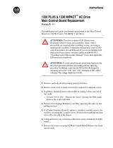
NOTE: The 10-watt audio PA
has "balanced outputs" and must be tested with the
test setup shown in Figure 1.
Figure 1 - Audio Output Test Setup
SERVICE AIDS
The following service aids are available to facilitate
serviceing and adjustments.
ST3712 Pin extractor Tool (11-03- 0038) - Allows removal
of contacts from connector shell that mates with
Option cable CC01. The option cable is required
with all external options.
ST2513 Alignment Tool - with two ceramic tips - used for
squelch control and other adjustments.
ST2617 Crimping Tool for field attachment of TNC - series
male connectors 19A115903P1 to RG-58/U (and
similar) coaxial cable.
Port Check Pin Toggle Rate
Pin Toggle Rate
4
5
6
8
9
14
5 kHz
2500 Hz
1250 Hz
312 Hz
156 Hz
78 Hz

LBI-38973 LBI-38973
7
TRANSMITTER ALIGNMENT
Frequency Set
Select any channel frequency. Key the transmitter and
measure the transmit frequency. The frequency should be
within ±250 Hz of the channel frequency. If it is not, adjust
U204 to within ±100 Hz.
NOTE
The temperature should be 25° ±5° C. Ensure frequency
counter calibration is better than ±0.1 PPM.
Audio Modulation Set
1. Apply a 1 kHz, 0.1 Vrms AC signal to the MIC HI
input. Note that MIC HI has a DC voltage present.
2. Turn on the TX audio (with Channel Guard). Key the
transmitter on a channel near the center of the frequency
band (806-821). Adjust modulation control R254 for
4.25 kHz ±0.2 kHz deviation.
3. Key the transmitter on a channel near the center of the
frequency band in the direct mode (851-866) and adjust
R226 for 4.25 kHz ±0.2 kHz deviation.
Transmitter Power Set
1. Key the transmitter and adjust R111 in the power
control circuit for 25 watts.
Channel Guard Check
1. Turn on the digital Channel Guard code 023. Verify
TX modulation is 0.75 kHz ± 0.25 kHz. Adjust R250
for minimum deviation.
RECEIVER ALIGNMENT
Frequency Set
1. Verify that the transmitter is on frequency as described
in the transmitter alignment procedure.
2. Inject a strong on-channel signal (-50 dBm) at the
antenna input J101.
3. Monitor J501 with a frequency counter and adjust L508
for a reading of 455 kHz ±100 Hz.
IF Tuning
1. Monitor J501 pin 1 with an AC voltmeter (pin 2 is
ground). Inject an on-channel signal at the antenna jack
modulated with a 1 kHz tone at 3 kHz deviation.
2. Adjust L504, L506, and L507 for a peak on the voltmeter.
Adjust the level of the generator to keep the signal at J501
out of limiting (approximately -65 dBm).
3. Repeak the coils.
Quadrature Detector Adjustment
1. Inject a strong (-60 dBm) on-channel signal at the
antenna jack modulated with a 1 kHz tone at 3.0 kHz
deviation.
2. Monitor the VOL/SQ HI output at J705-3 with an AC
voltmeter and adjust L509 for a peak indication on the
meter.
Receiver Audio Level
1. Inject a strong on-channel signal at the antenna jack
modulated with a 1 kHz tone at 3.0 kHz deviation.
2. Monitor VOL/SQ HI at J702-4 on the audio board with an
AC voltmeter. Adjust R513 on the RF board for a reading
of 200 ±20 mVrms.
Squelch Adjust
1. Select any channel. Apply a signal modulated with a 1
kHz tone at 3.0 kHz deviation to the antenna jack. Adjust
the squelch pot on the Audio Board fully open.
2. While monitoring SPKR HI and LO, adjust the signal
generator for 8 dB SINAD.
3. Adjust the squelch adjust potentiometer on the Audio
Board until squelch opens.
POWER DISTRIBUTION
Refer to the Power Distribution Block Diagram for an
understanding of the distribution of A+, SW A+, and the
regulated voltages throughout the radio.
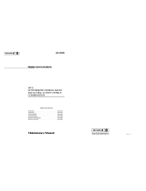
ALIGNMENT PROCEDURE
To align the radio, follow instructions in Transmitter and Receiver Alignment following this Figure. Refer to the
Assembly Diagrams for board location and to this Figure for adjustment and test point locations.
Figure 2 - Location of Controls and Adjustments, RF Board

LBI-38973 LBI-38973
8
A+
A+ (+13.8 volts nominal) enters the radio on the power
cable and is connected to the system board. A+ feeds
MOSFET switch Q903 providing SW A+ power to the audio
amplifier board through J902 and J901. A+ is also applied to
the display board through J707 and P707.
A+ leaves the system board on J903 and feeds the PA
board and RF transistor Q151 through feedthru capacitor
assembly Z903. D905 on the system board provides reverse
polarity protection for the radio. D904 provides overvoltage
positive spike protection on the system board A+ lead. A+
leaves the board on J151 and supplies power to PA module
U101 and Q101 on the RF board. Q101 supplies the power
control voltage to the PA module.
SW A+
Switched A+ (13.6 volts nominal) originates from the
MOSFET switch on the system board. The Ignition Sense lead
and the POWER push-button control the MOSFET switch.
Fuse F901 protects the MOSFET and the radio from high
current failures. SW A+ is supplied through J902 and J903 to
the front cap assembly. It provides power to the 5 volt
regulator, 10 watt audio PA, and the Front Cap Display Board.
J903 provides SW A+ to the PA board which, in turn, passes
SW A+ through J151 and J705 to the RF board.
SW A+ enters the RF board on J704 and J705 and
supplies power to three 8-volt regulators and the transmitter
power control circuitry. SW A+ leaves the RF board on J702
to supply power to 8-volt regulator U705 on the Logic Board.
SW A+ also goes through J703 on the Audio Board to supply
regulators U605, U606, and U607.
RF Board
8-volt regulator U502 provides power to the receiver. A
separate 8.3-volt regulator U207 and 5-volt regulator U203
provide power to the synthesizer. 8 volt regulator U102
provides power to the transmitter. The output of U102 is
switched to the exciter and the power control circuit. U503
powers the audio/logic board. U102 (TX 8-volt supply) and
Q101 (power control output transistor) are mounted for heat
sinking.
Logic Board
Requlator U705 receives SW A+ power and supplies 5
volt power to the logic devices on the board. SW A+ is routed
to connector J701 to supply power to an option handset for test
purposes.
Audio Board
Regulator U606 receives SW A+ power and
generates 8 volt power for the audio devices on the board.
The 8 volt power is further regulated to supply 5 volt bias
and pull up supply. SW A+ is used to generate a negative
supply (through Q602 and Q603) that supplies regulator
U605 which generates -5 volts to supply power for audio
devices.
Front Cap Assembly (Display Board)
A 5-volt regulator on the audio amplifier board
powers the microprocessor logic display, icon LED's.
Audio Amplifier Board
A +5-volt regulator U727, is used for logic level
pullups and to power the display board. SW A+ is used to
power audio amplifier board U801, and display board
backlighting control, Q850. An 8-volt regulator, U804, is
used to power the operational amplifiers.
AUDIO SIGNAL FLOW
Refer to the Audio Signal Flow Block Diagram to
see the distribution of RX and TX audio signals
throughout the radio. Audio levels at important points
are also shown.
Transmitter Audio
Microphone audio (MIC HI) is routed from the mic
connector on the display board through the audio
amplifier board to feed the Audio and Logic boards.
After processing and summing the Channel Guard tones,
the audio (TX MOD) is fed to the RF board. TX MOD is
adjusted by Deviation Adjust R226 before feeding the
modulation input to the synthesizer VCO U201.
Receiver Audio
Discriminator audio is buffered by Q503 on the RF
board and adjusted by R513. This audio (VOL/SQ HI) is
routed to the Audio and Logic boards for audio
processing, tone/code detection, and volume control.
LOGIC SIGNAL FLOW
Refer to the Logic Signal Flow Block Diagram to see
the distribution of logic signals throughout the radio.
APPENDIX A. GE-MARC TONES
Number Frequency Number Frequency
01
02
03
04
05
06
07
08
09
10
11
12
13
14
15
16
17
18
19
20
21
604.2 Hz
631.5 Hz
662.3 Hz
693.0 Hz
727.1 Hz
761.3 Hz
795.4 Hz
832.9 Hz
870.5 Hz
911.5 Hz
952.4 Hz
996.8 Hz
1041.2 Hz
1089.0 Hz
1140.2 Hz
1191.4 Hz
1243.0 Hz
1304.0 Hz
1362.1 Hz
1423.5 Hz
1488.4 Hz
22
23
24
25
26
27
28
29
30
31
32
33
34
35
36
37
38
39
40
41
42
1556.7 Hz
1628.3 Hz
1717.1 Hz
1795.6 Hz
1877.5 Hz
2051.6 Hz
2143.8 Hz
2239.4 Hz
2341.8 Hz
2447.6 Hz
2556.9 Hz
2672.9 Hz
2792.4 Hz
508.6 Hz
529.1 Hz
553.0 Hz
576.9 Hz
1962.9 Hz(acq)
2918.7 Hz(alt)
3051.9 Hz(std)
466.0 Hz

LBI-38973 BLOCK DIAGRAM LBI-38973
9
(19D904183 Sh. 1, Rev. 2)

LBI-38973 BLOCK DIAGRAM LBI-38973
10
(19D904183 Sh. 5 & 6, Revs. 3 & 3)

LBI-38973 BLOCK DIAGRAM LBI-38973
11
MDX GE-MARC 800 MHz
Power Distribution Diagram

LBI-38973 BLOCK DIAGRAM LBI-38973
12
MDX GE-MARC 800 MHz
Audio Signal Flow

LBI-38973 BLOCK DIAGRAM LBI-38973
13
MDX GE-MARC 800 MHz
Data Control Diagram
/