Page is loading ...

1
TOUCH SCREEN WEATHER STATION (WIND AND
AIR PRESSURE) WS-3512
Operation Manual

2
Table of Contents
i……………….About this Manual
ii………………Glossary of Common Terms
1..................... General
2...................... Important Operating Notes
3..................... Getting Started
3.1............... Wiring the System
3.2............... Power Supply
3.2.1......... Batteries
3.2.2......... AC/DC Mains Adapter
3.2.3......... Cable Connection
3.3............... System Start
3.4............... Positioning
4..................... Setting Up
5..................... Display of stored Min/Max and Alarm Value Settings
6..................... Radio-Controlled WWVB Clock
7..................... Weather Tendency
8..................... Air Pressure History
9..................... Features and Operations
9.1............... Air Pressure
10................... Wind Function Information
10.1............. Operating and Setting of Function Wind Direction
11................... Operating EL Backlight, Buzzer, and Alarm History
11.1............. EL Backlight
11.2............. Buzzer
11.3............. Alarm
12................... PC Connection
12.1............. Data Storage
12.2............. Data Recall
12.3............. Connections and Software
13................... Technical Data
13.1............. Outdoor Data
13.2............. Data Transmission by 433 MHz Signal and Cable
13.3............. Time alarm
13.4............. Power Supply
13.5............. PC Connection
13.6 ............ Dimensions
14................... Warranty Information

3
i. About this Manual
Thank You
and
Congratulations
on selecting a La Crosse
Technology Professional Weather Station! We are positive you will
enjoy the benefits of accurate weather readings and the precise, radio-
controlled time information that our instruments offer. La Crosse
Technology introduced radio-controlled instruments to the US market
in 1991 and continues to be on the cutting-edge of this technology in
America.
This manual will guide you step-by-step through setting up your La
Crosse Technology device. Use this manual to become familiar with
your professional weather station, and save it for future reference.
ii. Glossary of Common Terms
NIST*
The National Institute of Standards and Technology maintains the
primary frequency standard for the United States. The NIST also
coordinates the United States time and frequency standards with other
world standards. The NIST provides time and frequency services for
United States clientele.
WWVB*
The WWVB is an AM radio station in Ft. Collins, Colorado, managed
by the NIST. The WWVB’s function is to broadcast time-of-day
information derived from the NIST atomic clock, located in Boulder,
Colorado.
ATOMIC CLOCK*
An atomic clock is an extremely accurate time device measuring time
by the movements of electrons in cesium atoms. The NIST atomic
clock is one of the most precise clocks in the world, accurate to 10
billionths of one second. The NIST’s atomic clock contributes to the
international group of clocks calculating the Coordinated Universal
Time (UTC)—the official world time.

4
RADIO-CONTROLLED TIME*
A radio-controlled time device is often confused with an atomic clock.
However, a radio-controlled time device receives its time information
from the atomic clock each day through an internal antenna. The
radio- controlled time device searches for an exact time signal every
night when the signal from the WWVB is the strongest. The signal can
be received up to 2,000 miles away through a radio-controlled time
device.
LCD
“LCD” is an acronym for ”Liquid Crystal Display”. This is a common
type of display screen used in televisions, computers, watches, and
digital clocks.
BAROMETER & BAROMETRIC PRESSURE
A barometer is a device that measures the pressure of the air pushing
on it—this measurement is called the barometric pressure. We don’t
actually feel the barometric pressure because the air pressure is
pushing equally in every direction.
RELATIVE AIR PRESSURE
Relative air pressure is the same as the barometric pressure. The
calculation of relative air pressure is a combination of the absolute air
pressure and the altitude.
ABSOLUTE AIR PRESSURE
Absolute air pressure is the actual air pressure on the barometer
without regard to altitude.
INCHES OF MERCURY (inHg)
Inches of Mercury is the common unit of measurement for air pressure
in the United States.
HECTOPASCALS (hPa)
Hectopascals are the common units of measurement for air pressure
in the International System (SI) of measurement. The hectopascal
holds the same value

5
*For more information regarding the NIST, WWVB, atomic clock, and
radio-controlled time, please visit the NIST official website:
http://www.boulder.nist.gov/timefreq/stations/wwvb.htm
1 General
Important Note:
Before inserting batteries, please carefully read the
operation manual.
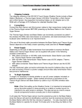
The Touch Screen Weather Station WS-3512 includes a Base Station
(Receiver), a Transmitter unit, one Wind Sensor, Connecting Cables,
an AC/DC Adapter, and a PC Software Package on CD-ROM.
The Base Station is equipped with a Touch Screen LCD Monitor and
allows the display of a large variety of time and weather data.
From top to bottom:
• Radio-Controlled Time (Time)
• Calendar (Date)
• Weather Forecast (Tendency)
• Air Pressure and Air Pressure History (Pressure, Pressure
History)
• Wind measurement
Also, the information text display (located at the bottom of the LCD),
will show a variety of additional data.
Note:
On the information text display, the min/max of today’s air pressure,
max wind speed, wind gust will be shown time by time. If the set-up
menu is selected, the information in the text display will be temporarily
replaced by the menu operating features.
An added feature of the Weather Station is the readout of all
measured and displayed time and weather data on a PC as well

6
as the ability to upload the data to Internet Web Sites.
2 Important Operating Notes
• All actions and functions of the Weather Station are started on the
Touch Screen by slightly touching (not pressing!) the switching
areas appearing with star (٭) symbols (only in the text section at
the bottom of the LCD) or the displayed values.
• The setting of functions, values, and units is performed by use of
the switching areas ٭ON٭ or ٭OFF٭, ٭UP٭ or ٭DOWN٭ or by
direct unit selection.
• Advancing to any next menu step with ٭NEXT٭, leaving or
terminating all modes with ٭EXIT٭.
• Every time a programming step is activated by touching a
switching area on the Touch Screen a tone will sound (with buzzer
switched ON).
• If no areas are pressed for 30 seconds, the LCD will automatically
revert to the normal display mode (automatic time out).

7
Note:
The presence of the "Alarm-On icon" in the section means that
the particular alarm has been enabled.
3 Getting Started
First you must decide whether to use batteries or the AC/DC adapter
to operate the system. Both methods allow the connection of
Transmitter unit and Base Station by cable or by 433 MHz radio signal.
Note:
When setting up the Weather Station it is important to tentatively
perform in close proximity (e.g. on a table) a complete wiring
and set-up of the system. This allows you to make sure all
Alarm history
selection key
Time section
Weather
Tendency
section
Date section
Pressure
History section
Pressure
section
Wind direction / Wind
speed / Wind gust
Backlight section
key
Buzzer selection
key
Text Display
(Set up Display)
Alarm
-On symbol
for time alarm
Alarm
-
On symbol
for pressure
Alarm
-On symbol for wind
speed/ gust/ wind direction
Symbol showing Storm-
warning alarm is On

8
Wireless
Transmission
Direct cable
connection
AC/ DC adap
ter
PC COM Port cable
Transmitter unit
components work properly before positioning them in their final
locations.
3.1 Wiring the System
Independent of the final operating mode at first, the fixed cable of the
Wind Sensor has to be connected to the Transmitter unit by plugging it
into the marked receptacle.
OUTDOOR
TX

9
The direct cable connection of Transmitter unit and Base Station can
be used if:
•
the flexibility of 433 MHz radio transmission is not needed and
•
data transmission absolutely free of any environmental
interferences is wanted.
3.2 Power Supply
The Weather Station can be powered by the use of batteries, by the
AC/DC adapter or, by direct cable connection.
3.2.1 Batteries:
•
First insert (2) "C" batteries into the battery compartment of the
Transmitter unit.
•
Immediately following this insert (3) AA 1.5V batteries into the
battery compartment of the Touch Screen Weather Station.
Please help in the preservation of the environment and
return used batteries to an authorized depot.
3.2.2 The AC/DC Adapter:
•
First insert (2) "C" batteries into the battery compartment of the
Transmitter unit.
•
Immediately following this, connect the AC/DC adapter to the
Base Station and then plug it into a regular outlet.

10
Note:
In both cases it is important to power the units in this order
because the transmitter will send an identification code which
has to be received and stored by the Base Station within the
first few minutes of operation.
After doing this, full operation of the entire Weather Station System is
ensured.
3.2.3 Cable Connection:
An additional feature of the direct cable connection (mentioned in Item
3.1 above) is when using the AC/DC adapter, power is provided to
both the Base Station and the Transmitter unit by only the AC/DC
adapter.
Note:
System operation with cable connection while at the same time
providing power to the Base Station solely by batteries is not
recommended due to the considerably higher power
consumption. The batteries may however remain in the unit for
emergency supply in case of a power failure.
A change from cable operation to 433 MHz radio transmission
or vice versa is possible because the Weather Station will
recognize this change and will automatically switch to the
appropriate operating mode.
OUTDOOR
TX

11
3.3 System Start
After inserting the batteries and connecting the AC/DC adapter, the
LCD of the Weather Station will, for a few seconds, display all possible
display segments for checking.
Immediately after this, the unit will enter the “play mode”, during which
for about 15 minutes all measured and received weather data are
being switched through, updated, and displayed. During this time
period there will be no reception of the WWVB time information.
Note:
The play mode phase allows the user of the Weather Station to
check all cables for correct connection and all components for
correct function. The latter will be possible by manually turning
the wind-gauge, moving the weather-vane, etc.
After completing the play mode, the Touch Screen Weather Station will
automatically switch to the normal display mode from which all further
settings can be performed by the user. At this point of time, the unit will
also automatically start reception of the WWVB time information.
Important Note:
Reception of the radio-controlled time information will only take
place after completion of the play mode (approx. 15 minutes). If
the user wants to start the system without waiting for completion
of the play mode it can be terminated prematurely by touching
the TIME display once in the upper left corner of the LCD.
Prior to manual setting or reception of radio-controlled time
information there will be no recording of weather history data.
3.4 Positioning
Once you have verified that all of the components of the weather
station are working, they can be positioned in their permanent places.
Before permanently mounting, make sure that all components work
properly together at their chosen mounting or standing locations. If e.g.
there appear to be problems with the 433 MHz radio transmission they
can mostly be overcome by moving the mounting locations.

12
Note: Commonly the radio communication between receiver and
transmitter in the open field can reach a distance of up to 330
feet providing that there are no interfering obstacles such as
buildings, trees, vehicles, high voltage lines, etc.
Radio interferences such as PC screens, radios or TV sets can,
in bad cases, entirely cut off radio communication. Please take
this into consideration when choosing standing or mounting
locations.
4 Setting Up
Note:
Because of the default settings already determined by the
manufacturer it may not be necessary for the majority of users
to perform – except the Relative Air Pressure (see further down)
- any further basic settings. Changes, however, can be easily
made.
For basic settings, the following menu is started by touching the Touch
Screen in the center of the text display (last 2 lines on the LCD).
Touching the display ٭SETUP٭ will enter the setup mode.
The basic settings can now be performed in the following successive
order:
LCD Contrast → Contrast can be set in 8 steps from 0 to 7 (Default
4).

13
Time Zone → Time Zones can be set in the range from -12 to +12
hours (Default EST).
WWVB Radio-Controlled Clock (RCC) → ON/OFF. In setting “OFF“
the clock is operating as a normal Quartz clock (Default RCC OFF).
12/24 hour Time Display Format
(Default 12h Format).
Units
• Wind Speed Display (Wind) in km/h, mph, m/s, knots or Beaufort
(Default mph).
• Air Pressure (Press) in hPa or inHg (Default inHg).
Relative Air Pressure
(Rel. Pressure) → To be set to the locally valid
reference air pressure with regard to the local height above sea level
(Default 29.98 inHg).

14
Weather Tendency
(Tendency) → Setting to a definite switching
threshold (2 hPa to 4 hPa) for a change in display of weather icons
(Default 3 hPa).
Storm Warning
(Storm) → Setting to a definite switching threshold for
storm warning display at a decrease of air pressure from 3 hPa to 9
hPa over 6 hours (Default 5 hPa).
Activate/Deactivate storm warning alarm with ٭ON٭ / ٭OFF٭ resp.
(Default OFF).
Relearn Mode
(Relearn Tx) → Allows recognition of the outdoor
transmitter (e.g. after a battery change in the transmitter) without the
necessity of a comprehensive re-setup of all system components →
Acknowledge with ٭CONFIRM٭.

15
Default Settings (Factory Reset) → Allows clearing of all weather
data in non-volatile buffer memory (EEPROM) and to reset of all set
and/or stored values to the factory settings set prior to shipment →
Acknowledge with ٭CONFIRM٭.
Note:
It will take 5 minutes for the factory reset process. During this period,
the text “Factory Reset In Progress” will be shown. After the reset
process is finished, the LCD will switch off and the text “Remove
Battery” will be displayed. Remove the battery and perform system
start again. See “3 - Putting in Operation” paragraph.
To leave the basic settings procedure (Setup Mode) touch ٭EXIT٭.
5 Display of Stored MIN/MAX Alarm Value
Settings
Named values are in each case upon recall being simultaneously
displayed and flashing in their respective display sections.
To recall measuring and alarm values, the menu shown below will
have to be activated by touching the Touch Screen in the center of the
text display section (last 2 lines at the bottom of the LCD). The display
of the values is started by touching the displays ٭MINMAX٭ or
٭ALARMS٭.

16
With ٭MINMAX٭ the below shown menu step is activated, which in
return leads to the displays of the stored Min/Max values by use of
٭MIN٭ / ٭MAX٭, which on their part again can be directly selected.
Note: During individual displays of the stored Min/Max values the top
line of the LCD screen will automatically display the time and
date of their storage.
The following menu item will appear upon touching the display labelled
٭ALARMS٭.
Because of the constant access to the respective opposite menu item
٭MINMAX٭/٭ALARMS٭, it is possible at any time to toggle between
the MIN/MAX and ALARMS value displays.
Any action can immediately be terminated through ٭EXIT٭.
6 Radio-Controlled WWVB Clock
The Radio-Controlled WWVB Clock is normally controlled by the radio
signal of the WWVB time code transmitter and will thus set time and
date automatically. Under bad reception conditions however both can
be set manually as follows:
Setting the Time
The action is started by touching the time display in the TIME section
of the Touch Screen.

17
Start ٭TIME٭ in the menu section (last 2 lines on the LCD).
Set the hours and minutes. Leave the mode with ٭EXIT٭ or wait for
automatic time-out.
Setting the Date
The action is started by touching the date display in the DATE section
of the Touch Screen.
Set the year, month and date of day. Leave the mode with ٭EXIT٭.

18
Note: By touching the DATE section twice, the display will toggle
between the following:
• Date in MM.DD.YY format (12 hour time format) or Date in
DD.MM.YY format (24 hour time format)
• Weekday, Month, Date of Day (12 hour time format) or
Weekday (in English abbreviation), Date of Day, Month (24 hour
format)
• Seconds
• Set Wake-up Alarm Time
Setting of Wake-up Alarm
The action is started by touching the time display in the TIME section.
Start ٭ALARM٭ in the menu section (last two lines on the LCD).
Set hours and minutes of the wake-up time. Leave the mode with
٭EXIT٭.
Note:
The wake-up alarm is activated/deactivated by twice touching
the TIME section. Here the alarm symbol (((•))) will show or
disappear after ٭EXIT٭ (or automatic time-out).
7 Weather Tendency
Call up the tendency display by touching the weather symbol in the
TENDENCY section.

19
The text section (last 2 lines on the LCD) will show because (with time
and date) the weather condition corresponds to the presently
displayed weather symbol Sunny, Fair (Cloudy with sunny intervals) or
Rainy.
Note:
• Up and down arrow indicate weather tendency
• Advanced storm warning is displayed by Rainy symbol with a
flashing down arrow
• Every minute, when a new pressure reading is obtained, this
value is compared to pressure readings from last 2 hours and
the biggest resulting difference is displayed in the difference
barometer.
8 Air Pressure History
The air pressure history shows the progress of the air pressure over a
time period of 24 or 72 hours in form of a 7-step bar graph, where the
length of the utmost right bar represents the present air pressure and
the remaining bars show the progress of the air pressure with regard
to the present air pressure.
Note: The time resolution of the bar graph can be changed from fine
(0 to -24 h) to coarse (0 to -72 h) and back by touching the
PRESSURE HISTORY section once.

20
9 Features and Operations
• Air Pressure (Pressure), Relative and Absolute
• Wind Speed, Wind Gust
Important Note!
Because the operating procedures in all measurements are
identical, the various functions of the weather station will be
explained once here by the following example of “Air Pressure”.
9.1 Air Pressure
Example for Activating the Displays of Stored Maximum Values
Call up the menu on the text section by touching the PRESSURE
section. (Similarly, if user wants to check the wind measurements, the
WIND section should be touched.)
Start with ٭MAX٭ in the menu section.
Note:
Display of the stored minimum values is from here possible
through ٭MIN٭ analog to this example.
Display of stored value. Proceed with ٭MAX PRESSURE٭.
/