Page is loading ...

FormNo.3430-978RevA
LightKit
TXL2000ToolCarrier
ModelNo.136-4890
InstallationInstructions
Installation
1
PreparingtheMachine
NoPartsRequired
Procedure
1.Parkthemachineonalevelsurface.
2.Lowertheloaderarms.
3.Shutofftheengineandremovethekey.
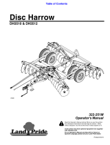
4.Opentherear-accesscover.
5.Turnthebattery-disconnectswitchtotheOFF
position(Figure1).
g261512
Figure1
1.Battery-disconnect
switch—OFFposition
2.Battery-disconnect
switch—ONposition
2
InstallingtheLights
Partsneededforthisprocedure:
2Light
1
Leftlightbracket
1Rightlightbracket
1
Switch
2Thread-cuttingscrew
2
Bolt(5/16x1inch)
2
Nut(5/16inch)
Procedure
1.Removethe2thread-cuttingscrewsandplate
fromthecontrolpanel(Figure2).Discardthe
plate.
g283294
Figure2
1.Thread-cuttingscrew(2)
2.Plate
©2019—TheToro®Company
8111LyndaleAvenueSouth
Bloomington,MN55420
Registeratwww.T oro.com.
OriginalInstructions(EN)
PrintedintheUSA
AllRightsReserved
*3430-978*A

2.Installtheleftlightbracketusing2thread-cutting
screws(Figure3).
g283291
Figure3
1.Thread-cuttingscrew(2)2.Leftlightbracket
3.Removethebolt,washer,andnutfromalight
andusethemtosecurethelighttothebracket
(Figure4).
g283290
Figure4
1.Bolt3.Washer
2.Light4.Nut
4.Installtherightlightbrackettothetowerplate
using2bolts(5/16x1inch)and2nuts(5/16
inch)asshowninFigure5.
g283292
Figure5
1.Lightbolt5.Washer
2.Light6.Lightnut
3.Bolt—5/16x1inch(2)7.Nut—5/16inch(2)
4.Rightlightbracket
5.Removetheboltandnutfromtheotherlight
andusethemtosecurethelighttothebracket
(Figure5).
2

3
RoutingtheWireHarness
Partsneededforthisprocedure:
1Wireharness
2
Cabletie
Procedure
RefertoFigure6toidentifythewireharness
connectors.
g283649
Figure6
1.Leftlightconnector
3.Machinewireharness
connector
2.Switchconnector
4.Rightlightconnector
1.Removethe4thread-cuttingbolts(5/16x3/4
inch)securingtheconsoleplatetothemachine
(Figure7).
g283650
Figure7
1.Thread-cuttingbolt(5/16x3/4inch)
2.Pullouttheplatesothatyoucanaccessinside
themachine.
3.Opentherear-accesscover.
4.Removetheplugfromanaccessoryconnector
onthemachinewireharness(P50,P75,orP76)
andplugthekitwireharnesstoit(Figure8).
g282599
Figure8
1.Kitwireharness
2.Accessoryconnectorfrom
machinewireharness
5.Securethewireharnesstothemachinewire
harnessusingacabletieneartheconnectors.
6.Routetherightlightconnectorouttherightside
ofthemachine,uptothelight(Figure9).Plug
theconnectortothelight.
3

g283803
Figure9
1.Wireharness
3.Cabletie
2.Rightlight
7.Securethewireharnesstothegrabbarusing
acabletie(Figure9).
8.Routetheleftlightandswitchconnectors
throughtheholeontheleftsideofthemachine
(Figure10).
g283648
Figure10
9.Usingtheconsoleplateopeningtoaccess
thewireharness,routetheleftlightconnector
throughtheholeintheleftlightbracketand
connectittotheleftlight(Figure11).
g283780
Figure11
10.Removethesecondplugontheconsoleplate
andinstalltheswitch(Figure12).Connectthe
wireharnesstotheswitch.
g283801
Figure12
1.Switchconnector2.Switch
11.Securetheconsoleplatetothemachineusing
the4thread-cuttingboltsremovedpreviously
(Figure7).
4

4
InstallingtheReectors
Partsneededforthisprocedure:
2
Reector(2x3inches)
2
Reector(1-1/2x6inches)
Procedure
1.Thoroughlycleanthesurfacesonthebackof
themachineandthefrontoftheloaderarmsin
thelocationsshowninFigure13andFigure14.
2.Adherethereectorstothemachine.
g283844
Figure13
1.Reector(1-1/2x6inches)
g283845
Figure14
1.Reector(2x3inches)
5
CompletingtheInstallation
NoPartsRequired
Procedure
1.Turnthebattery-disconnectswitchtotheON
positionandclosetherearcover.
2.Startthemachine.
3.Usetheswitchtoverifythatthelightsturnon
andoff.
5

Notes:

Notes:

/