Toro Light Kit, Dingo Compact Tool Carrier Installation guide

Type
Installation guide

Toro Light Kit, Dingo Compact Tool Carrier is an illuminating accessory designed to enhance visibility during low-light conditions when operating your Dingo Compact Tool Carrier. With this kit, you can effortlessly add two powerful lights to your machine, providing ample illumination for nighttime tasks, dimly lit areas, or even during foggy or dusty conditions. The kit includes all the necessary hardware and detailed instructions, making the installation process straightforward and convenient.

Toro Light Kit, Dingo Compact Tool Carrier is an illuminating accessory designed to enhance visibility during low-light conditions when operating your Dingo Compact Tool Carrier. With this kit, you can effortlessly add two powerful lights to your machine, providing ample illumination for nighttime tasks, dimly lit areas, or even during foggy or dusty conditions. The kit includes all the necessary hardware and detailed instructions, making the installation process straightforward and convenient.

FormNo.3447-286RevA
LightKit
Dingo
®
CompactToolCarrier
ModelNo.144-7101
InstallationInstructions
Installation
LooseParts
Usethechartbelowtoverifythatallpartshavebeenshipped.
ProcedureDescription
Qty.
Use
1
Nopartsrequired
Preparethemachine.
2
Nopartsrequired
Removetheaccesspanels(TX525
only).
Light2
Carriagebolt(5/16x1inch)
2
Flatwasher4
Rubbergrommet2
Nut(5/16inch)
6
Leftlightbracket
1
Rightlightbracket1
Thread-formingbolt(5/16x3/4inch)
4
3
Curvedwasher(320-Dor323traction
unitonly)
2
Installtherightlight.
Wireharness1
4
Cabletie
2
Routethewireharness.
5
Fuse(10A)—525tractionunitonly
1
Completetheinstallation.
1
PreparingtheMachine
NoPartsRequired
Procedure
1.Parkthemachineonalevelsurface.
2.Engagetheparkingbrake.
3.Lowertheloaderarms.
4.Shutofftheengineandremovethekey.
5.Openorremovethehood,asapplicableforyour
machine.
6.Removethenegative(-)batterycablefromthe
battery.
©2021—TheToro®Company
8111LyndaleAvenueSouth
Bloomington,MN55420
Registeratwww.Toro.com.
OriginalInstructions(EN)
PrintedintheUSA
AllRightsReserved
*3447-286*
2
RemovingtheAccess
Panels
TX525TractionUnitsOnly
NoPartsRequired
RemovingtheFusePanel
1.Pullthehairpincotterfromthebottomendofthe
hoodprop-rodandslidetheproprodoutofthe
retainingbracketsandtheprop-rodtab.
g004984
Figure1
1.Prop-rodtab4.Retaining
bracket—bottom
2.Retainingbracket—top5.Hairpincotter
3.Proprod
2.Removethe4screwssecuringthefusepanel
andthenpullthepaneloutanduptoremoveit.
g004985
Figure2
1.Fusepanel
2.Screw
RemovingtheRearPanel
1.Unscrewthe2handknobssecuringthe
rear-accesscovertothemachine(Figure3).
g244210
Figure3
2.Tilttherear-accesscoverdown(Figure3)and
removeittoaccesstheinternalcomponents.
2
3
InstallingtheLights
Partsneededforthisprocedure:
2Light
2
Carriagebolt(5/16x1inch)
4Flatwasher
2Rubbergrommet
6
Nut(5/16inch)
1
Leftlightbracket
1Rightlightbracket
4
Thread-formingbolt(5/16x3/4inch)
2
Curvedwasher(320-Dor323tractionunitonly)
320-Dor323TractionUnits
Note:Only2thread-formingboltsareneededwhen
installingthekiton320-Dor323tractionunits.
1.Installtherightlightbracket.
g342135
Figure4
1.Rightlightbracket
3.Thread-formingbolt(5/16
x3/4inch)
2.Curvedwasher
2.Installalighttotheouterholeofthebracket.
g342140
Figure5
1.Carriagebolt(5/16x1
inch)
4.Rubbergrommet
2.Light
5.Nut(5/16inch)
3.Flatwasher
3.Installtheleftlightbracket.
g342138
Figure6
1.Leftlightbracket3.Thread-formingbolt(5/16
x3/4inch)
2.Curvedwasher
3
4.Installtheotherlightandtheswitchtothe
bracket.
g342137
Figure7
1.Switch
4.Flatwasher
2.Carriagebolt(5/16x1
inch)
5.Rubbergrommet
3.Light
6.Nut(5/16inch)
TX427orTX525TractionUnits
1.Installtherightbracket.
g357089
Figure8
1.Nut(5/16inch)3.Thread-formingbolt(5/16
x3/4inch)
2.Rightlightbracket
2.Installalighttothebracket.
g342140
Figure9
1.Carriagebolt(5/16x1
inch)
4.Rubbergrommet
2.Light
5.Nut(5/16inch)
3.Flatwasher
3.Installtheleftlightbracket.
g357088
Figure10
1.Thread-formingbolt(5/16
x3/4inch)
3.Nut(5/16inch)
2.Leftlightbracket
4.Installtheotherlightandtheswitchtothe
bracket.
4
g342137
Figure11
1.Switch
4.Flatwasher
2.Carriagebolt(5/16x1
inch)
5.Rubbergrommet
3.Light
6.Nut(5/16inch)
4
RoutingtheWireHarness
Partsneededforthisprocedure:
1Wireharness
2
Cabletie
320-Dor323TractionUnits
g342266
Figure12
1.Leftlight
4.Machinemainharness
2.Switch
5.Rightlight
3.Fuse(10A)
1.Connectthewireharnesstotheleftlightand
switch.
g342264
Figure13
1.Machinewireharness
connectorP06
3.Leftlight
2.Switch
2.Routethewireharnessinsidetheleftoperator
gripandtheninfrontofthecontrolpanel,behind
thehoses.
3.Connectthewireharnesstothemachinewire
harness(P06).
5
4.Routethewireharnessbehindthehosesand
insidetherightoperatorgrip.
g342265
Figure14
1.Rightlight
5.Connecttherightlight.
6.Securethewireharnesstotheleftlightbracket.
g342385
Figure15
1.Cabletie
2.Leftlightwireharness
7.Securethewireharnesstothebottomow
dividerhose(320-Dtractionunitsonly)ortothe
front,leftsideofthecontrolpanel.
g342450
Figure16
1.Flowdivider(320-D
tractionunitsonly)
2.Cabletie
TX427orTX525TractionUnits
g342398
Figure17
1.Leftlight
4.Machinemainharness
2.Switch
5.Rightlight
3.Fuse(10A)
1.Removethebrake-leverknob.
g357027
Figure18
1.Leftcontrolpanelcover(4
bolts)
3.Brake-leverknob
2.Rightcontrolpanelcover
(5bolts)
2.Removetheleftandrightcontrolpanelcovers.
3.Cutaslotinbothcontrolpanelcoversasshown.
6
WARNING
Usingadrillwithoutpropereye
protectionmayallowdebristoenterthe
eye,causinginjury.
Whendrillingorcarryingoutother
operation,alwaysweareyeprotection.
g357025
Figure19
Leftcontrolpanelcover
g357024
Figure20
Rightcontrolpanelcover
4.Connectthewireharnesstotheleftlightand
switch.
g342402
Figure21
1.Leftlight2.Switch
5.Routethewireharnessintothecontrolpanel
andthroughtheopeningintheframetowardthe
enginecompartment.
7
6.Routethewireharnessacrossthefrontofthe
machineandconnectthewireharnesstothe
machinewireharness(P09).
g342396
Figure22
1.Kitmachineharness
connector
3.Fuse
2.Lightkitconnectorfrom
machinewireharness
(P09)
7.Routethewireharnessbacktothecontrolpanel
andconnectittotherightlight.
g357028
Figure23
1.Rightlight.
8.Installtheleftandrightcontrolpanelcovers,
ensuringthatthewireharnessgoesthroughthe
notches(seeFigure18).
9.Securethewireharnesstotheleftlightbracket.
g342385
Figure24
1.Cabletie2.Leftlightwireharness
10.Securethewireharnesstotherightlightbracket.
g342453
Figure25
1.Cabletie
2.Rightlightwireharness
8
5
CompletingtheInstallation
Partsneededforthisprocedure:
1
Fuse(10A)—525tractionunitonly
Procedure
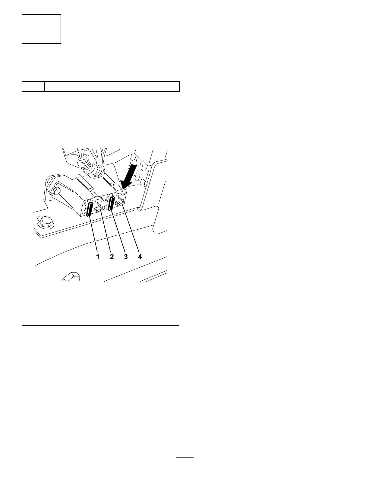
1.FortheTX525,performthefollowingsteps:
A.Installthefuse(10A)tothefuse-block
locationshowninFigure26.
g357029
Figure26
1.Existingfuse(30A)3.Existingfuse(10A)
2.Empty
4.Addlightkitfuse(10A)
here.
B.Installthefuseandrearpanels.
Note:Reversetheproceduresforeach
panelasshownin2RemovingtheAccess
Panels(page2).
2.Installthenegative(-)batterycabletothe
battery.
3.Closeorinstallthehood,asapplicableforyour
machine.
4.Startthemachineandverifythatthelights
functionusingtheswitch.
9
Notes:
Notes:
  • Page 1 1
  • Page 2 2
  • Page 3 3
  • Page 4 4
  • Page 5 5
  • Page 6 6
  • Page 7 7
  • Page 8 8
  • Page 9 9
  • Page 10 10
  • Page 11 11
  • Page 12 12

Toro Light Kit, Dingo Compact Tool Carrier Installation guide

Type
Installation guide

Toro Light Kit, Dingo Compact Tool Carrier is an illuminating accessory designed to enhance visibility during low-light conditions when operating your Dingo Compact Tool Carrier. With this kit, you can effortlessly add two powerful lights to your machine, providing ample illumination for nighttime tasks, dimly lit areas, or even during foggy or dusty conditions. The kit includes all the necessary hardware and detailed instructions, making the installation process straightforward and convenient.

Ask a question and I''ll find the answer in the document

Finding information in a document is now easier with AI