Page is loading ...

4010ES
Fire Alarm
Operator’s
Manual
579-969
Rev. C

ii
Copyright © 2011-2016 Tyco Fire Protection Products. All rights reserved. All specifications and other
information shown were current as of document revision date and are subject to change without
notice.
TYCO, SIMPLEX, and the product names listed in this material are marks and/or registered marks.
Unauthorized use is strictly prohibited.
Cautions
and
Warnings
READ AND SAVE THESE INSTRUCTIONS- Follow the instructions in this installation manual. These instructions must be
followed to avoid damage to this product and associated equipment. Product operation and reliability depend upon proper
installation.
DO NOT INSTALL ANY SIMPLEX® PRODUCT THAT APPEARS DAMAGED- Upon unpacking your Simplex product,
inspect the contents of the carton for shipping damage. If damage is apparent, immediately file a claim with the carrier and notify
an authorized Simplex product supplier.
ELECTRICAL HAZARD - Disconnect electrical field power when making any internal adjustments or repairs. All repairs should
be performed by a representative or authorized agent of your local Simplex product supplier.
STATIC HAZARD - Static electricity can damage components. Handle as follows:
• Ground yourself before opening or installing components.
• Prior to installation, keep components wrapped in anti-static material at all times.
EYE SAFETY HAZARD - Under certain fiber optic application conditions, the optical output of this device may exceed eye
safety limits. Do not use magnification (such as a microscope or other focusing equipment) when viewing the output of this device.
FCC RULES AND REGULATIONS – PART 15 - This equipment has been tested and found to comply with the limits for a Class A digital device
pursuant to Part 15 of the FCC Rules. These limits are designed to provide reasonable protection against harmful interference when the equipment is
operated in a commercial environment. This equipment generates, uses, and can radiate radio frequency energy and, if not installed and used in accor-
dance with the instruction manual, may cause harmful interference to radio communications. Operation of this equipment in a residential area is likely to
cause harmful interference in which case the user will be required to correct the interference at his own expense.
SYSTEM REACCEPTANCE TEST AFTER SOFTWARE CHANGES - To ensure proper system operation, this product must be tested in
accordance with NFPA-72, after any programming operation or change in site-specific software. Reacceptance testing is required after any change,
addition or deletion of system components, or after any modification, repair or adjustment to system hardware or wiring.
All components, circuits, system operations, or software functions known to be affected by a change must be 100% tested. In addition, to ensure that
other operations are not inadvertently affected, at least 10% of initiating devices that are not directly affected by the change, up to a maximum of 50
devices, must also be tested and proper system operation verified.
Cautions, Warnings and Copyrights

Ch. 1. Basic Concepts and Operations - - - - - - - - - - - - - - - - - - - - - - - - - 1-1
Introduction............................................................................................................................1-1
In this Chapter.......................................................................................................................1-1
Basic System Description. . . . . . . . . . . . . . . . . . . . . . . . . . . . . . . . . . . . . . . . . . . . . . . . . 1-2
Overview................................................................................................................................1-2
Normal Appearance of Operator Interface Panel . . . . . . . . . . . . . . . . . . . . . . . . . . . . . .1-4
Description.............................................................................................................................1-4
Ch. 2. Alarm Conditions - - - - - - - - - - - - - - - - - - - - - - - - - - - - - - - - - - - - 2-1
Introduction............................................................................................................................2-1
In this Chapter.......................................................................................................................2-1
Acknowledging an Alarm . . . . . . . . . . . . . . . . . . . . . . . . . . . . . . . . . . . . . . . . . . . . . . . . . 2-2
How the 4010ES Indicates that an Alarm has Occurred .......................................................2-2
Overview - Acknowledging Alarms........................................................................................2-2
Globally Acknowledging Alarms ............................................................................................2-3
Individually Acknowledging Alarms .......................................................................................2-3
Silencing an Alarm. . . . . . . . . . . . . . . . . . . . . . . . . . . . . . . . . . . . . . . . . . . . . . . . . . . . . . .2-5
Overview................................................................................................................................2-5
Using the Alarm Silence Key.................................................................................................2-5
Resetting the System . . . . . . . . . . . . . . . . . . . . . . . . . . . . . . . . . . . . . . . . . . . . . . . . . . . .2-6
Overview................................................................................................................................2-6
Resetting a System with Active Alarms.................................................................................2-6
Performing a Hardware Reset...............................................................................................2-7
Disabling a Point that Remains in Alarm. . . . . . . . . . . . . . . . . . . . . . . . . . . . . . . . . . . . . 2-8
Overview................................................................................................................................2-8
Important Notes.....................................................................................................................2-8
Procedure..............................................................................................................................2-8
Ch. 3. Trouble Conditions- - - - - - - - - - - - - - - - - - - - - - - - - - - - - - - - - - - 3-1
Introduction............................................................................................................................3-1
In this Chapter.......................................................................................................................3-1
Overview. . . . . . . . . . . . . . . . . . . . . . . . . . . . . . . . . . . . . . . . . . . . . . . . . . . . . . . . . . . . . . . 3-2
How the 4010ES Indicates the Presence of a Trouble..........................................................3-2
What Acknowledge Does ......................................................................................................3-2
Global Versus Individual Acknowledge .................................................................................3-2
Trouble Indications for TrueAlarm Sensors...........................................................................3-3
What to do when TrueAlarm Troubles Occur ........................................................................3-3
Table of Contents

Acknowledging Troubles . . . . . . . . . . . . . . . . . . . . . . . . . . . . . . . . . . . . . . . . . . . . . . . . .3-4
Globally Acknowledging Troubles .........................................................................................3-4
Individually Acknowledging Troubles.....................................................................................3-4
If the Trouble Doesn’t Clear . . . . . . . . . . . . . . . . . . . . . . . . . . . . . . . . . . . . . . . . . . . . . . . 3-6
Overview................................................................................................................................3-6
System Reset Key.................................................................................................................3-6
Disabling a Point with a Trouble Condition............................................................................3-6
Ch. 4. Supervisory Conditions - - - - - - - - - - - - - - - - - - - - - - - - - - - - - - - 4-1
Introduction............................................................................................................................4-1
In this Chapter.......................................................................................................................4-1
Overview. . . . . . . . . . . . . . . . . . . . . . . . . . . . . . . . . . . . . . . . . . . . . . . . . . . . . . . . . . . . . . . 4-2
How the 4010ES Indicates the Presence of a Supervisory Condition...................................4-2
What Acknowledge Does ......................................................................................................4-2
Acknowledging Supervisory Conditions. . . . . . . . . . . . . . . . . . . . . . . . . . . . . . . . . . . . . 4-3
Globally Acknowledging Supervisory Conditions ..................................................................4-3
Individually Acknowledging Supervisory Conditions..............................................................4-3
Ch. 5. Selecting Points for Status and Control - - - - - - - - - - - - - - - - - - - 5-1
Introduction............................................................................................................................5-1
In this Chapter.......................................................................................................................5-1
Selecting Points from Alarm, Trouble, Supervisory List . . . . . . . . . . . . . . . . . . . . . . . . 5-2
Procedure..............................................................................................................................5-2
Selecting Points from the Menu. . . . . . . . . . . . . . . . . . . . . . . . . . . . . . . . . . . . . . . . . . . . 5-3
Procedure..............................................................................................................................5-3
Selecting Points with the Entry Keypad . . . . . . . . . . . . . . . . . . . . . . . . . . . . . . . . . . . . .5-4
Overview................................................................................................................................5-4
Selecting Points.....................................................................................................................5-4
Ch. 6. Advanced Functions- - - - - - - - - - - - - - - - - - - - - - - - - - - - - - - - - - 6-1
Introduction............................................................................................................................6-1
In this Chapter.......................................................................................................................6-1
Logging In and Out of the System . . . . . . . . . . . . . . . . . . . . . . . . . . . . . . . . . . . . . . . . . . 6-2
Introduction............................................................................................................................6-2
Log In Procedure...................................................................................................................6-2
Log Out Procedure ................................................................................................................6-3
Setting System Time and Date . . . . . . . . . . . . . . . . . . . . . . . . . . . . . . . . . . . . . . . . . . . . .6-4
Procedure..............................................................................................................................6-4
Viewing the Time at which an Event Occurred . . . . . . . . . . . . . . . . . . . . . . . . . . . . . . . . 6-5

Overview................................................................................................................................6-5
Procedure..............................................................................................................................6-5
Enabling and Disabling Points. . . . . . . . . . . . . . . . . . . . . . . . . . . . . . . . . . . . . . . . . . . . .6-6
Overview................................................................................................................................6-6
Procedure..............................................................................................................................6-6
Forcing Points On and Off . . . . . . . . . . . . . . . . . . . . . . . . . . . . . . . . . . . . . . . . . . . . . . . . 6-7
Overview................................................................................................................................6-7
Forcing Points ON and OFF..................................................................................................6-7
Returning a Point to Automatic Operation.............................................................................6-7
Displaying and Clearing Historical Logs. . . . . . . . . . . . . . . . . . . . . . . . . . . . . . . . . . . . .6-8
Overview................................................................................................................................6-8
Displaying/Clearing Historical Logs.......................................................................................6-8
Printing Reports. . . . . . . . . . . . . . . . . . . . . . . . . . . . . . . . . . . . . . . . . . . . . . . . . . . . . . . . .6-9
Overview................................................................................................................................6-9
Procedure............................................................................................................................6-10
Ch. 7. System Test Procedures- - - - - - - - - - - - - - - - - - - - - - - - - - - - - - - 7-1
Introduction............................................................................................................................7-1
In this Chapter.......................................................................................................................7-1
Lamp Test / Tone Alert Test . . . . . . . . . . . . . . . . . . . . . . . . . . . . . . . . . . . . . . . . . . . . . . . 7-2
Overview................................................................................................................................7-2
Performing a Lamp Test........................................................................................................7-2
Testing the Tone-Alert...........................................................................................................7-2
WalkTest Overview . . . . . . . . . . . . . . . . . . . . . . . . . . . . . . . . . . . . . . . . . . . . . . . . . . . . . . 7-3
Overview................................................................................................................................7-3
Important Notes.....................................................................................................................7-3
Setting WalkTest Options . . . . . . . . . . . . . . . . . . . . . . . . . . . . . . . . . . . . . . . . . . . . . . . . .7-4
Enabling WalkTest for a Group .............................................................................................7-4
Setting Options......................................................................................................................7-4
TrueNAC Voltage Drop Test . . . . . . . . . . . . . . . . . . . . . . . . . . . . . . . . . . . . . . . . . . . . . . .7-5
Overview................................................................................................................................7-5
Accessing the TrueNAC Voltage Drop Test..........................................................................7-5
Testing all TrueAlert Power Supply’s SLCs...........................................................................7-6
Testing each TrueAlert Power Supply’s SLC ........................................................................7-7
The TrueNAC Report.............................................................................................................7-8
TrueNAC Report Samples.....................................................................................................7-8
Disable IDNET CO Algorithms . . . . . . . . . . . . . . . . . . . . . . . . . . . . . . . . . . . . . . . . . . . .7-11
Overview..............................................................................................................................7-11
Disable IDNET CO Algorithms without WalkTest Enabled..................................................7-12
Disable IDNET CO Algorithms with WalkTest Enabled.......................................................7-12


1-1
Chapter 1
Basic Concepts and Operations
Introduction This chapter provides an overview of the 4010ES operator interface panel and describes the normal
appearance of the operator interface panel.
In this Chapter Refer to the page number listed in this table for information on a specific topic.
Topic See Page #
Basic System Description 1-2
Normal Appearance of Operator Interface Panel 1-4

1-2
Overview The Simplex 4010ES Fire Alarm Control Panel (FACP) has three general functions.
• It monitors fire alarm initiating points (for example, smoke detectors, heat detectors, and pull
stations).
• It activates fire alarm notification appliances (horns, strobes, audio evacuation messages) when
an initiating point activates.
• It monitors and controls auxiliary building equipment (fan dampers, relays, security devices).
Note: The term “point” is used extensively throughout this manual. It is a generic term used to refer
to an individual component of the system, such as a single smoke detector, a single pull
station, etc.). Some devices may take up multiple points in a system.
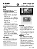
The 4010ES operator interface, shown in Figure 1-1, allows a system operator to control and monitor
the facility-specific components connected to the 4010ES FACP.
Figure 1-1. Operator Interface
Continued on next page
Facility-Specific
Control Keys
and LEDs
Entry
Keypad
Table 1-1. Components of the Operator Interface
LED/Key Description Refer To
ALARMS Keys and
LEDs
The ALARMS LEDs - FIRE and
PRORITY2 - indicate the presence of
an unacknowledged alarm condition.
Other components of the system,
such as the horns and strobes, also
activate to indicate the presence of
an alarm. The FIRE ALARM ACK
and PRIORITY2 ACK keys allow an
operator to acknowledge the
presence of an alarm.
Chapter 2
ALARM SILENCED
LED/ALARM SILENCE
Key
Pressing the ALARM SILENCE key
provides a means of silencing the
building’s audible notification
appliances (horns). The LED
indicates when this key has been
used.
Chapter 2
Basic System Description

1-3
Basic System Description, Continued
Overview
Note: The degree to which you are allowed to control the system depends on the passcode
assigned to you. See “Logging in and Out of the System” for details on this.
Table 1-1. Components of the Operator Interface (continued)
LED/Key Description Refer To
WARNING LED Keys
and LEDs
The WARNINGS LEDs –
SUPERVISORY and TROUBLE –
indicate when abnormal, non-fire
conditions occur to the fire alarm’s
wiring or devices. The Warning keys
– SUPV ACK and TROUBLE ACK –
allow an operator to acknowledge the
presence of the abnormal condition.
Chapter 3 for
Troubles.
Chapter 4 for
Supervisory
Conditions
SYSTEM RESET Key
Pressing this key directs the panel to
reset all attached devices and clear
all acknowledged alarms, troubles,
and supervisory conditions.
Chapter 2
AC POWER LED
Indicates the presence of AC power
at the panel.
N/A
Event Time Key
Used to display the time at which an
acknowledged alarm, trouble, or
supervisory condition occurred.
Chapter 6
Entry Keypad
Used to call up points for monitoring
and control.
Chapter 5
Facility-Specific Control
Keys
These are programmable keys.
Typical functions include manual
evacuation, ground fault monitor, etc.
N/A
Enable/Disable Keys
Pressing these keys allows you to
enable or disable devices attached to
the panel.
Chapter 6
On/Off/Auto Keys
Pressing these keys allows you to
force a device (such as a relay) ON or
OFF. The Auto key returns control of
the device to the panel.
Chapter 6
Arm/Disarm Keys
Used with security points. These
keys allow you to turn security
devices on (arm) or off (disarm).
Chapter 6
Alphanumeric Display
Displays text describing abnormal
conditions for devices attached to the
panel (i.e., smoke detector in main
lobby is in alarm). Also displays
system prompts and messages.

1-4
Normal Appearance of Operator Interface Panel
Description The 4010ES operator interface panel shows the following under normal conditions.
• Green power LED is ON - indicating the panel is receiving AC Power
• All other LEDs off.
• Alphanumeric display reports that the system is normal, as shown below.
Note: If the appearance of the operator interface panel is not as shown above, refer to the
information in Chapters 2, 3, and 4 for instructions on managing the alarm, supervisory, or
trouble condition.
SYSTEM IS NORMAL
08:23:45 MON 14-NOV-10

2-1
Chapter 2
Alarm Conditions
Introduction An alarm condition occurs when an initiating device (such as a manual pull station, smoke detector,
etc.) activates. The 4010ES indicates the presence of the alarm condition through messages it
displays on the alphanumeric display, by flashing the ALARM indicator, and by activating the
building’s notification appliances (horns and strobes).
Note: An alarm condition is a serious event, indicating the possibility of fire danger.In addition to
using the 4010ES operator interface panel to investigate and manage alarm conditions as
described in this chapter, you should also be aware of any facility-specific procedures that
you may be required to follow.
In this Chapter Refer to the page number listed in this table for information on a specific topic.
Topic See Page #
Acknowledging an Alarm 2-2
Silencing an Alarm 2-5
Resetting the System 2-6
Disabling a Point that Remains in Alarm 2-8

2-2
Acknowledging an Alarm
How the 4010ES
Indicates that an
Alarm has
Occurred
When an alarm condition is detected by the 4010ES, the panel does the following to indicate the
presence of the alarm.
• Red LED, labeled Fire Alarm flashes.
• Tone-alert (piezo buzzer) pulses.
• LEDs on remote annunciators may illuminate.
• The alphanumeric display on the interface panel indicates an alarm condition. The exact manner
in which the alphanumeric display reports information for the alarm condition depends on
whether the system’s Display First Alarm Option is enabled.
- If Display 1st Alarm Option is Enabled. The display alternates between two screens
similar to Screen 1 and Screen 2 shown below. Screen 1 is a tally screen indicating the total
number of fire alarms, priority 2 alarms, supervisory conditions, and trouble conditions pres-
ent on the panel. Screen 2 is a detailed description of the first alarm received by the panel.
- If Display 1st Alarm Option is not enabled. Only a screen similar to Screen 1 appears,
indicating the total number of alarm conditions present on the system.
Overview -
Acknowledging
Alarms
The first step in managing an alarm condition is to acknowledge the alarm. Acknowledging an alarm
does two important things:
• It records the time and date at which you observed the presence of an alarm, trouble, or
supervisory condition on the operator interface panel and stores that information in the system’s
historical log.
• When you press the acknowledge key, the system displays specific data on the location of the
alarm.
It is important to understand that the 4010ES can be configured with either Global or Individual
Acknowledge. Global or Individual Acknowledge is selected in the System Options sub-tab of the
Panel Tab in the ES Panel Programmer. Global Acknowledge is the default. These options function as
follows:
• Global Acknowledge. When global acknowledge is enabled, one press of the FIRE ALARM
ACK (or the PRIORITY 2 ACK) key acknowledges every abnormal point currently reporting an
alarm status. This is helpful when a series of devices enter an alarm state (for example, all of the
smoke detectors in an area of the building) and you want to acknowledge all of them at the same
time.
• Individual Acknowledge. If individual acknowledge is enabled, the FIRE ALARM ACK (or
PRIORITY 2 ACK) key must be pressed to individually acknowledge each alarm. Individual
acknowledge must be selected if the panel is providing proprietary receiving service in
accordance with NFPA72.
The FIRE ALARM ACK (or the PRIORITY 2 ACK) key, which is used to acknowledge alarms
(either globally or individually), is located just beneath the ALARMS LEDs.
Continued on next page

2-3
Acknowledging an Alarm, Continued
Globally
Acknowledging
Alarms
Use the following procedure if the Global Acknowledge option is enabled on your 4010ES system.
1. Unlock and open the enclosure door. Read the alphanumeric display on the interface panel. It
reports the number of alarm conditions as shown below.
2. Press the FIRE ALARM ACK key. Read and follow the instructions on the alphanumeric display.
After you press the FIRE ALARM ACK key, the system responds as follows:
• The tone-alert silences and the alphanumeric display reports pertinent information about the
alarm, such as the following:
• The ALARMS LED changes from flashing to steady ON, and all alarm conditions are
acknowledged.
• Pressing the FIRE ALARM ACK key again displays information on the next alarm.
Continue to do this to review all alarms in the system.
Individually
Acknowledging
Alarms
Use the following procedure if the Individual Acknowledge option is enabled on your 4010ES
system.
1. Unlock and open the enclosure door. Read the alphanumeric display on the interface panel. It
reports the number of alarm conditions as shown below.
2. Press the FIRE ALARM ACK key. A report similar to the one shown below appears. Read and
follow the instructions on the alphanumeric display.
Continued on next page

2-4
Acknowledging an Alarm, Continued
Individually
Acknowledging
Alarms
3. Press the FIRE ALARM ACK key again. Read the report data. Repeat this procedure to review
all reports. Reports are displayed in chronological order.
• Tone-alert silences when the last unacknowledged alarm is acknowledged.
• System Alarm LED is ON, but is no longer flashing.

2-5
Silencing an Alarm
Overview When an alarm condition exists, various signals (horns and strobes), auxiliary relays, the city
connection (which is the link to the local fire department or central station monitoring service), and
the tone-alert may activate. The ALARM SILENCE key turns OFF all devices that are programmed
to turn off when it is pressed. Typically, this will be the audible notification appliances (horns).
Note: Depending on the programming of the system, some devices may not turn off when the
ALARM SILENCE key is pressed.
At a minimum, the following occurs when the key is pressed.
• Turns OFF signal circuits (which usually connect to the Notification Appliances).
• Turns ON the ALARM SILENCED LED.
• Displays “Alarm Silence In Progress”.
You should be aware that the following functions affect the operation of the ALARM SILENCE
function.
•If a Coded Input Device (typically a pull station) activates, the <ALARM SILENCE> key may
be ignored until this function has completed coding. Notification appliances (horns) cannot be
silenced when a coded station is in alarm, but silence upon coding completion.
•If the Alarm Silence Inhibit Option -- which is a timer that inhibits the operation of the
ALARM SILENCE function – is enabled, pressing the <ALARM SILENCE> key is ignored
until the timer expires. The message “ALARM SILENCE INHIBITED” displays for a short
time to indicate the action was not taken. The message “ALARM SILENCE NO LONGER
INHIBITED” displays when the timer expires.
•If Waterflow Sprinkler Devices are activated, Notification Appliances may or may not be
silenced (depending on local code requirements). Usually, a dedicated bell will continue to
sound to indicate water flow.
• Some visual notification appliances may continue to flash until the system is reset.
Using the Alarm
Silence Key
Press the ALARM SILENCE key and read the display. The alphanumeric display shows signal status
and the ALARM SILENCED LED turns ON steady.
ALARM SILENCE IN PROGRESS

2-6
Resetting the System
Overview The function of the SYSTEM RESET key depends on whether active alarms are present at the time
the key is pressed.
• Active Alarms Present. Pressing the SYSTEM RESET key when alarms are present attempts
to return the system to its normal state. This includes resetting initiating devices (pull stations
and smoke detectors, for example), relays (including city relay and door holder relays),
notification appliances (horns and strobes), and all LEDs and indicators that have been
programmed to be reset with the SYSTEM RESET key. See “Resetting a System with Active
Alarms” below for more information.
• No Active Alarms Present. Pressing the SYSTEM RESET key when no alarms are present
causes the system to perform a hardware reset. See “Performing a Hardware Reset” below for
more information.
Resetting a System
with Active Alarms
Activated devices (i.e, devices in alarm) can be reset, using the SYSTEM RESET key. Doing this
allows the system to return to a normal state following alarm activation. Follow these steps to
perform a System Reset when alarms are present.
1. Press the SYSTEM RESET key. The following message appears.
2. One of the following occurs, depending on whether the activated devices reset or not.
• If all zones or devices in alarm reset, the ALARMS LEDs flash. Press either the FIRE
ALARM ACK or the PRIORITY 2 ACK key or both, and the following message appears.
• If a zone or device remains in alarm and fails to reset, the “SYSTEM RESET IN PROG-
RESS” message is followed by the message shown below.
When this message appears, the system remains in an alarm state. The display indicates the total
number of alarms present in the system along with a prompt to use the FIRE ALARM ACK (or
PRIORITY 2 ACK) key to review the points. (These points do not require acknowledgment.) The
ALARMS LED remains ON to indicate that a fire alarm device is still in the alarm condition. Read
the display to determine the type and location of the device. Follow local procedures to investigate
the area of the building in alarm. Look for devices that are in an alarm state, for example, pull
stations with the handle down or smoke detectors with their LED lit.
SYSTEM RESET IN PROGRESS
SYSTEM IS NORMAL
8:37:13 WED 17-NOV-10
ALARM PRESENT, SYSTEM RESET ABORTED

2-7
Resetting the System, Continued
Performing a
Hardware Reset
A hardware reset reinitializes the state of certain hardware components and is typically used to reset a
Class A Trouble (for example, on an IDNet or RUI channel) after the problem causing the trouble is
resolved. If you attempt to perform a hardware reset without first fixing the problem causing the
trouble, the hardware reset fails and the trouble reappears.
To perform a hardware reset, do one of the following:
• Press the SYSTEM RESET key when no alarms are present.
• From the Main Menu, go to Diagnostic Functions and select Hardware Reset.

2-8
Disabling a Point that Remains in Alarm
Overview If a device remains in alarm and no alarm condition (i.e., smoke or an activated pull station) exists,
the 4010ES provides a way to inhibit alarm reporting for the malfunctioning point. Disabling a point
causes a trouble condition for the point or zone that you disable.
The DISABLE key, which is used to disable points, may be passcode protected. If it is, you need to
first log in to the system using the passcode that enables the key. Refer to “Logging In and Out of the
System” in Chapter 6 for information on doing this.
Important Notes Be aware of the following issues related to disabling points.
• Disabling a point causes the point to NOT report alarm conditions or other status changes. A
point should not be disabled unless it is clearly understood that fire detection or security for the
area of the building covered by that point will be lost. Appropriate steps must be taken to
provide alternate means of protecting the area of the building covered by the disabled point.
• If the Service Reset option is enabled, an operator can clear an alarm condition (i.e., successfully
perform a system reset) even though the device that caused the alarm remains in a trouble state.
The typical application for this would be the case where a malfunctioning initiating device such
as a smoke detector (consisting of a base and removable sensor) causes an alarm and activates the
city circuit. With this option enabled, the sensor can be removed and the system (including the
city circuit) can be reset. Without this option enabled, removing the sensor would cause a
trouble, which would prevent the city circuit from being reset.
Important Note: Service Reset is not a UL-Approved option and enabling this option on the panel
invalidates the panel’s UL certification.
Procedure To disable a point in alarm, follow these steps.
1. Log in at a minimum level of 3.
2. Press either the FIRE ALARM ACK or the PRIORITY 2 ACK key (depending on the type of
alarm) to display the point’s information on the alphanumeric display. For example:
3. Press the DISABLE key. The alphanumeric display shows the following message.
Note: XX represents the point to be disabled.
Continued on next page

2-9
Disabling a Point that Remains in Alarm, Continued
Procedure 4. Press the ENTER key. The alphanumeric display shows the action taken.
Note: The system indicates a trouble condition each time a point is disabled. It is important to repair
the disabled point as soon as possible. Once repaired, the disabled point should be enabled
as soon as possible. See the procedure in “Enabling and Disabling Points” in Chapter 6 of
this manual.

3-1
Chapter 3
Trouble Conditions
Introduction A Trouble message is used to indicate that the FACP is impaired, for example, due to an open circuit,
short circuit, ground fault, etc.
This chapter describes using the Operator Interface Panel keys to investigate the details of the trouble
condition.
In this Chapter Refer to the page number listed in this table for information on a specific topic.
Topic See Page #
Overview 3-2
Acknowledging Troubles 3-4
If the Trouble Doesn’t Clear 3-6
/