INSTRUCTIONS
PORTO® and PORTO® XL INSTALLATION
RAB Lighting is committed to creating high-quality, aordable, well-designed and energy-ecient LED lighting and controls that make it easy for electricians to install
and end users to save energy
.
We
’
d love to hear your comments. Please call the Marketing Depar
tment at 888-RAB-1000 or email:
[email protected] Page 1
IMPORTANT
READ CAREFULLY BEFORE INSTALLING FIXTURE. RETAIN THESE INSTRUCTIONS FOR FUTURE REFERENCE.
RAB xtures must be wired in accordance with the National Electrical Code and all applicable local codes. Proper grounding is
required for safety. THIS PRODUCT MUST BE INSTALLED IN ACCORDANCE WITH THE APPLICABLE INSTALLATION CODE BY A PERSON
FAMILIAR WITH THE CONSTRUCTION AND OPERATION OF THE PRODUCT AND THE HAZARDS INVOLVED.
WARNING: Make certain power is OFF before installing or maintaining xture. No user serviceable parts inside.
CAUTION: For proper weatherproof function all gaskets must be seated properly and all screws inserted and tightened
rmly. Apply weatherproof silicone sealant around the edge of the ceiling mounting box and/or junction box. This is
especially important with an uneven ceiling surface. Silicone all plugs and unused conduit entries.
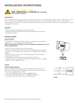
PORTO® PORTO® XL
Junction
Box
Plugs (4)
Gaskets
Screws (2)
LED
Housing
Screws (2)
Screws (2)
EZ Hang Hook
Gaskets
Fixture
Wires
Screws (2)
Junction
Box
NPS Adaptor
Fig: 1
Fig: 2
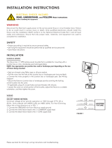
CEILING MOUNTING
PENDANT MOUNTING
The xture is suitable for outdoor applications in wet locations.
1. Loosen Screws (2) to free Junction Box from LED Housing.
Remove NPS Adaptor as marked (Fig. 2) if mounting directly to
ceiling surface without junction box.
2. Mount Junction Box to ceiling by knocking out (4) Knock Out
Locations as marked in Fig. 3. Use the appropriate mounting
hardware for the mounting surface. May alternately be mounted
to recessed junction boxes.
3. For hands-free wiring, hang the xture on the EZ Hang Hook as
shown in Fig 1. Connect supply wires to Fixture Wires. Supply
can come from back or through either of four 1/2” Plugs to make
electrical splices. Use appropriate UL approved wire connectors as
required by code to complete wiring.
4. Close xture and tighten Screws (2).
5. If mounting surface is irregular, use caulk to seal any gaps around
Junction Box.
Fixture can be mounted to a 1/2” or 3/4” NPS Pendant. 1/2” to 3/4”
NPS Adaptor is included.
1. Feed supply wires through Pendant (supplied by others)
2. Loosen Screws (2) on LED Housing.
3. Remove 1/2” plug and mount Junction Box to Pendant. For 3/4”
Pendant, remove plug and NPS Adaptor. Hang LED xture with
EZ Hang Hook as shown in Fig. 1
4. Make supply connections wiring sections as shown in Ceiling
Mounting section above.
5. Close xture and tighten Screws (2).