RAB Lighting ARBAY3-215/LCS/E2 Operating instructions

Type
Operating instructions
INSTRUCTIONS
AEROBAY® INSTALLATION
RAB Lighting is committed to creating high-quality, affordable, well-designed and energy-efficient LED lighting and controls that make it easy for electricians to install
and end users to save energy. We’d love to hear your comments. Please call the Marketing Department at 888-RAB-1000 or email: [email protected]
IMPORTANT
READ CAREFULLY BEFORE INSTALLING FIXTURE. RETAIN THESE INSTRUCTIONS FOR FUTURE REFERENCE.
RAB fixtures must be wired in accordance with the National Electrical Code and all applicable local codes. Proper grounding is required
for safety. THIS PRODUCT MUST BE INSTALLED IN ACCORDANCE WITH THE APPLICABLE INSTALLATION CODE BY A PERSON FAMILIAR
WITH THE CONSTRUCTION AND OPERATION OF THE PRODUCT AND THE HAZARDS INVOLVED.
WARNING:
• Make certain power is OFF before installing or maintaining fixture. No user serviceable parts inside.
1. Using two hands, pull Center Housing Channel straight up
as shown in Fig 1.
2. Center Housing Channel will lock into position as shown
in Fig. 2.
3. Verify that the Center Housing Channel is locked in place
IMPORTANT: Once the fixture has been fully expanded into the
operating position, do not collapse the Center Housing Channel
without first depressing the Release Clips.
Follow Steps below to install sensor before mounting/wiring
fixture.
(Applicable for units ordered with Passive InfraredOccupancy Sensor or
LCS, Lightcloud Motion Sensor.)
1. Remove applicable knockouts to install sensor as shown
in Fig. 3.
2. Run sensor wire through the knockout at end of the fixture and
connect internally.
3. Place Sensor Arm onto the fixture and secure with Screw
(provided) as shown in Fig.4.
4. Arm will lock into place, secure with screw (provided).
PREPARING FOR INSTALLATION
FOR SENSOR ARM MOUNTING
FIG. 1
FIG. 2
FIG. 3
FIG. 4
Center Housing Channel
(Pull Up)
(Pull Up)
(BEFORE) (AFTER)
Sensor Arm
Screw
Sensor
Sensor Arm
Knockout (2)
Sensor
CORD AND PLUG OPTIONS
For units ordered with the following suffixes see voltage
information below.
(/8C) 8ft Cord (only), 120-277V, 480V
(/ 8CP) 8ft Cord & Straight Plug, 120V (only), NEMA 5-15P
(/8CPT) 8ft Cord & Twist Lock Plug, 120V (only) NEMA L5-15P
(/8CP2) 8ft Cord & Straight Plug, 277V (only), NEMA 7-15P
(/8CPT2) 8ft Cord & Twist Lock Plug, 277V (only) NEMA L7-15P
(/8CPT4) 8 ft Cord & Twist Lock Plug, 480V (only) NEMA L8-20P
Minimum distance between fixture and ceiling is 16 inches.
Release Clips
INSTRUCTIONS
AEROBAY® INSTALLATION
RAB Lighting is committed to creating high-quality, affordable, well-designed and energy-efficient LED lighting and controls that make it easy for electricians to install
and end users to save energy. Wed love to hear your comments. Please call the Marketing Department at 888-RAB-1000 or email: [email protected]
FOR VHOOK MOUNTING OR CHAIN MOUNTING
010V DIMMABLE WIRING
Mount Housing to sturdy ceiling structure as follows:
1. V-Hooks (2) and Chain are provided for mounting. Secure
V-Hooks through Bracket Hole at back of Center Housing
Channel, or secure chains through Chain Mounting Slots in the
ends of the housing shown in Fig. 5.
2. Fixture mounting height and spacing should be determined by
application requirements.
3. Remove Access Plate and feed supply wire with strain relief
connector. Make electrical connections as shown in wiring
diagram (Fig. 7). Use approved wiring connectors and wire
to local NEC codes. Push all wires back into Center Housing
Channel. Be careful not to pinch wires.
4. Reinstall Access Plate and secure with supplied Screw (1).
(Accessory ordered separately - Model# JBARBAY2)
1. Choose length of 1/2” NPS Pendant Stem (supplied by others).
2. Install Pendant Junction Box (ordered separately) to Center
Housing Channel by mounting Pendant Junction Box on
Center Housing Channel and securing with supplied Screws (4)
and Washers (4) as shown Fig. 6.
3. Feed wires through Pendant Stem and into Pendant Junction
Box. Wire the housing leads to supply wires using UL listed wire
connectors according to NEC and local codes in the Pendant
Junction Box. Push all wires back into Pendant Junction Box,
install Side Panels (2) with supplied Screws (2). Be careful not to
pinch wires.
Universal voltage driver permits operation at 120V thru 277V,
50 or 60 Hz. Units ordered with (/480) suffix are 480V, 50Hz
or 60Hz. For 0-10V Dimming, follow the wiring directions as
shown Fig. 7.
1. Connect the black fixture lead to the LINE supply lead.
2. Connect the white fixture lead to the COMMON supply lead.
3. Connect the GROUND wire from fixture to supply ground.
4. Connect the purple fixture lead to the (V+) DIM lead.
5. Connect the gray fixture lead to the (V-) DIM lead.
Note: These instructions do not cover all details or variations in equipment nor do they provide for every possible situation during installation, operation or maintenance.
FIG. 7
FIG. 5
FIG. 6
NOTE: Do not connect DIM V+ (purple)/ DIM V- (gray)
to line voltage or supply ground.
FOR PENDANT MOUNTING
V Hooks (2)
Bracket Hole (4)
Access Plate
Center Housing Channel
Pendant Stem
(supplied by others)
Pendant Junction Box
(ordered separately
MODEL#JBARBAY2)
Screw (1)
Screw (2)
Screw (4)
Washer (4)
Side Panel (2)
WIRING DIAGRAM
Center Housing
Channel
Chain Mounting Slot
Chain Mounting Slot
INSTRUCTIONS
AEROBAY® INSTALLATION
RAB Lighting is committed to creating high-quality, affordable, well-designed and energy-efficient LED lighting and controls that make it easy for electricians to install
and end users to save energy. Wed love to hear your comments. Please call the Marketing Department at 888-RAB-1000 or email: [email protected]
To reduce the risk of electric shock, disconnect both normal and emergency power supplies and converter connector of the emergency driver before servicing. Do not attempt to service the emergency
driver. The use of accessory equipment may cause an unsafe condition. Do not use this product for other than intended use. Refer any servicing indicated by these checks to a Qualified Service Personnel.
DIMENSIONAL DRAWINGS
2 FT
4 FT
3 FT
3
1/2
36”
12
1/2
3
1/2
12
1/2
24
1/8
3
1/2
12
1/2
47
1/8
TROUBLESHOOTING CLEANING & MAINTENANCE
1. Check that the line voltage at the fixture is correct.
2. Be sure the fixture is grounded properly.
CAUTION: Be sure fixture temperature is cool enough to
touch. Do not clean or maintain while fixture is energized.
1. Lens can be washed only after removing from fixture and
only in a solution of warm water and any mild, non-abrasive
household detergent, rinsed with clean water and wiped dry.
Do not use chemicals to clean Lens or fixture.
2. Do not open fixture to clean the LED. Do not touch the LED.
Note: These instructions do not cover all details or variations in
equipment nor do they provide every possible situation during
installation, operation or maintenance.
Easy Answers
rablighting.com
Visit our website for product info
Tech Help Line
Call our experts - 888 722-1000
e-mail
Answered promptly - [email protected]
Free Lighting Layouts
Answered online or by request
© 2019 RAB LIGHTING Inc.
Northvale, New Jersey 07647 USA
Easy Answers
rablighting.com
Visit our website for product info
Tech Help Line
Call our experts - 888 722-1000
e-mail
Answered promptly - [email protected]
Free Lighting Layouts
Answered online or by request
© 2019 RAB LIGHTING Inc.
Northvale, New Jersey 07647 USA
RAB Lighting is committed to creating high-quality, affordable, well-designed and energy-efficient LED lighting and controls that make it easy for electricians to install
and end users to save energy. Wed love to hear your comments. Please call the Marketing Department at 888-RAB-1000 or email: [email protected]
INSTRUCTIONS
AEROBAY® INSTALLATION
AEROBAY-IN-0220 RAB WARRANTY: RAB’S warranty is subject to all terms and conditions found at rablighting.com/warranty.
Note: These instructions do not cover all details or variations in
equipment nor do they provide for every possible situation during
installation, operation or maintenance.
OPERATION
1. When AC power is applied, the charging indicator light is
illuminated, indicating that the BATTERY is being charged.
2. When power fails, the standby power automatically switches
to emergency power (internal battery), operating at reduced
illumination. Not all LED boards will illuminate with standby
power. The emergency driver supplies 25W of power in
standby power for a minimum of 90 minutes.
3. When AC power is restored, the emergency driver
automatically returns to charging mode.
Although no routine maintenance is required to keep the
emergency driver functional, it should be checked periodically
to ensure that it is working. The following schedule is
recommended:
1. Visually inspect the charging indicator light monthly. It should
be illuminated.
2. Test the emergency operation of the fixture at 30-day
intervals for a minimum of 30 seconds.
3. Conduct a 90-minute discharge test once a year. Fixture
would operate at reduced illumination for a minimum of
90 minutes.
TROUBLESHOOTING
MAINTENANCE
1. Is the fixture grounded properly?
2. If the charging indicator light does not illuminate after pressing
the test button, check if battery is connected properly.
BATTERY BACKUP MODELS
WIRING
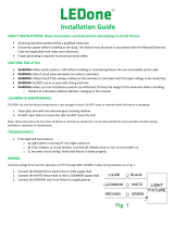
CAUTION: FOR BATTERY BACKUP FIXTURE. Voltage could be
present in BAT TERY. To prevent high voltage from being present
on output leads, inverter connector must be open. Do not join
BATTERY connector until installation is complete and AC power is
supplied to the emergency driver (Fig. 8)
NOTE: Make sure that the necessary branch circuit wiring is
available. An UNSWITCHED AC source of power is required. The
emergency driver must be fed from the same branch circuit as the
LED driver.
CAUTION: Do not use any supply voltage other than 120-277V
50/60 HZ.
1. Connect UNSWITCHED HOT fixture lead to HOT AC supply line.
2. If using an UNSWITCHED circuit, connect UNSWITCHED and
SWITCHED lines together.
3. If using a SWITCHED circuit, connect SWITCHED HOT AC fixture
lead to the external SWITCHED.
4. Connect the NEUTRAL fixture lead to the NEUTRAL supply line.
5. For 0-10V Dimming, connect DIM (+) and DIM (-) to the supply
DIM (+) and DIM (-).
6. Connect GROUND lead from the fixture to the supply ground.
Do not connect GROUND to the output leads.
7. All unused lead must be capped and insulated.
8. After installation is complete, supply AC power to the fixture and
connect the BATTERY.
9. When power is on, the fixture should be on and the Charging
Indicator Light should illuminate to indicate the battery is
charging.
10. Once the BATTERY has charged for at least one hour, a short
duration test may be performed by pressing the test button.
11. After the battery has charged for 24 hours, a long duration test
can be performed by shutting power to the fixture.
LIGHT
FIXTURE
BATTERY
CONNECTOR:
CONNECT
ONLY AFTER
AC SUPPLY
POWER IS
CONNECTED
BACKUP
DRIVER
INSIDE FIXTURE
BATTERY
FIG. 8
73651-RAB
  • Page 1 1
  • Page 2 2
  • Page 3 3
  • Page 4 4

RAB Lighting ARBAY3-215/LCS/E2 Operating instructions

Type
Operating instructions

Ask a question and I''ll find the answer in the document

Finding information in a document is now easier with AI