Huawei S2700 User guide

Type
User guide

Huawei S2700 series switches are ideal for building enterprise networks, data centers, and campus networks. They provide a variety of features, including:

  • High-speed switching: Huawei S2700 switches offer wire-speed switching for all ports, ensuring smooth data transmission without bottlenecks.

  • Extensive security features: Huawei S2700 switches support a variety of security features, such as access control lists (ACLs), port security, and virtual private networks (VPNs), to protect your network from unauthorized access and attacks.

  • Robust Quality of Service (QoS): Huawei S2700 switches support advanced QoS features, such as traffic classification, scheduling, and congestion control, to ensure that critical traffic is prioritized and delivered with low latency.

HUAWEI TECHNOLOGIES CO., LTD.
Quick Start Guide
S2700, S3700, S5700, and S6700 Series Switches
Issue: 37 (2021-02-28)
Part Number:
31504991
Thank you for purchasing a Huawei S series switch. This guide describes how to install S2700, S3700,
S5700, and S6700 series switches. It also explains how to log in to your switch for the first time.
For more information, see the for your switch on the
Huawei support website.
The installation, cable connection, and login methods for most S series switches are similar. This
guide uses the S5700-24TP-SI-AC as an example.
Figures in the document are for reference only and may be dierent from actual devices.
Any procedural dierences between models are specified at the start of each section.
1 About This Guide
Chassis (with the product model on the nameplate)
Power cable (Power cables are delivered with the
switch if the switch is equipped with built-in
power supply or pluggable power modules, and
are delivered with power modules in other cases.)
Installation accessory package:
-
- Rubber pads
- Chassis ground cable
- Dust plugs
- Warranty Card
- Mounting brackets
- Screws
The numbers and types of items in the installation accessory package dier for dierent product models.
Some switches have dust plugs delivered with them. Keep the dust plugs properly and use them to protect idle optical ports.
NOTE
2 Packing List
3 Safety Guidelines
To ensure personal and equipment safety, observe all the safety precautions on the equipment
and in this document. WARNING and CAUTION items do not cover all the safety precautions and
are only supplementary to the safety precautions.
Follow all the safety precautions and instructions provided by Huawei. The safety precautions
outlined in this document are only requirements of Huawei and do not include general safety
requirements. Huawei is not liable for any consequence that results from violation of regulations
pertaining to safe operations or safety codes pertaining to design, production, and equipment use.
This is a class A product. In a domestic environment this product may cause radio interference in which case the
user may be required to take adequate measures.
Take ESD protection measures during equipment installation and maintenance. For example, wear ESD gloves or
an ESD wrist strap.
Do not place other objects on the chassis.
WARNING
CAUTION
Laser beams will cause eye damage. Do not look into bores of optical modules or optical fibers without eye protection.
Do not install power cables while the power is on.
Do not turn on the power until you have finished installing the chassis and connecting cables.
1
Hardware Installation and Maintenance Guide
Quick Start Guide
2
4 Site Environment
Do not place this product in an environment with flammable or explosive gases, or smoke.
The installation site must be free from leaking or dripping water, heavy dew, and humidity. If the
relative humidity is high, use dehumidifiers or dehumidifying air conditioners.
The installation site must be well ventilated. Ensure that air vents on the equipment are not blocked.
Do not install the equipment in a dusty environment.
Grounding the switch helps protect it from lightning, electromagnetic interference, and
electrostatic discharge, and is the prerequisite for a PoE switch to provide power for a PD.For
switch models with the ground point at the left or right side of the chassis, connect the ground
cable before mounting the switch in the cabinet or rack.
Leave at least 50 mm clearance at the rear and both sides of the chassis for heat dissipation.
S series switches use forced, intelligent, or natural heat dissipation mode. If multiple switches are
installed in a cabinet/rack, leave at least 1 U (44.45 mm) distance between each two switches.
This distance is recommended for switches using forced or intelligent heat dissipation, and is
required for switches using natural heat dissipation.
Ensure that the temperature and humidity at the installation site meet the switch operation requirements.
For the specific requirements, see the for your switch on the Huawei support website.
Ethernet cables used outdoors must be buried underground or routed through steel pipes to
protect the switch from lightening. Do not route Ethernet cables overhead.
To protect network ports from lightning, use 8-line surge protectors or Huawei certified 4-line
surge protectors. When installing a network port surge protector, connect the IN ports to network
devices and connect the OUT ports to network ports of the switch.
5 Installing the Chassis
Scenario 1: Desk Mounting
S5710-HI, S6700-EI and S6720-HI series switches cannot be desk mounted.
Do not stack fanless switches on top of or closely next to each other.
Some switch models provide a security slot ( ) near the panel on a side of the chassis. You can
install a security lock (separately purchased) in this slot to protect the switch against theft.
Before You Start
Installation Procedure
Attach four rubber pads to the bottom.
Place the chassis on a desk.
Step 1
Step 2
(Optional) Install a security lock.
Connect the ground cable to the
ground point.
Step 3
Step 4
Scenario 2: Wall Mounting
Before drilling holes in a wall, make sure there are no power cables in the wall to avoid electric shock.
Before You Start
Hardware Description
For a wall-mounted switch, take water-proofing and dust-proofing measures to protect the switch from
damage caused by water and dust.
The S5720-16X-PWH-LI-AC, S6720S-S, and S6730 (220-mm deep models) need to be installed with the
port side facing up.
Ensure that there are no flammable or explosive materials near the switch and no obstructions
within 100 mm around the switch.
S3700-HI, S5700-HI, S6720S-EI, and other 420 mm or deeper switches cannot be wall mounted.
The expansion bolts need to be purchased separately.
Use a hammer drill with φ8 drill bit to drill
holes on the wall, and fix the switch on the
wall with expansion bolts.
Connect the ground cable to the ground point.
Step 2
Step 3
Step 1 Use M4 screws to fix the mounting brackets on both sides close to the port side.
Expansion bolt
Port side faces down
Installation Procedure
3
Scenario 3: Top Wall Mounting
Before drilling holes in a wall, make sure there are no power cables in the wall to avoid electric shock.
Only the S5720-16X-PWH-LI-AC can be installed on the top wall.
Expansion bolts and top-mounting brackets must be self-provided.
360 mm
180 mm
Before You Start
Installation Procedure
Mark the positions to drill holes according to the switch's size and positions of top-mounting brackets.
Use M4 screws to attach two top-mounting brackets to the switch.
Use a hammer drill (with φ8 drill bit) to drill holes, and use expansion bolts to secure the switch on
the top wall.
Connect the ground cable to the ground point.
Step 1
Step 2
Step 3
Step 4
When a chassis uses Category-6 or higher Ethernet cables, the distance between the port side and
interior side of the cabinet door must be larger than or equal to 120 mm.
Switches cannot be installed in a 600 mm deep cabinet when they are equipped with 1150 W PoE
power modules.
To install a 250 mm wide switch in a 19-inch cabinet, purchase long mounting brackets.
For the 220 mm deep models of the S2700 and S3700 series, and the S5700-24TP-SI-AC/DC, each
mounting bracket needs to be fixed on the chassis with only two screws.
The floating nuts and M6 screws are not delivered with the switch and need to be separately
purchased if needed.
S6700-EI chassis is heavy, so it is recommended that you install guide rails (separately purchased)
in the cabinet to support the chassis.
Scenario 4: Cabinet/Rack Mounting
S series Ethernet switches can be installed in a 19-inch standard cabinet/rack. Cabinets purchased
from other vendors must have enough space for equipment installation.
If the distance between front and rear mounting rails is not within the required range, install guide
rails or a tray in the cabinet/rack to support the chassis. Guide rails or trays are not delivered with
the product and must be purchased separately.
Before You Start
4
Ensure a distance of 418–528 mm or 545–655 mm between the front and rear mounting rails.
Cable management frames are recommended when many cables are used.
Leave 2 U between the floating nuts on each front mounting rail, and 1 U between those on the rear rails.
Ensure the lower floating nut on each mounting rail is level with those on the other mounting rails.
S5710-HI
Connect the ground cable to the switch.
Use M4 screws to attach a mounting bracket delivered with the switch to each side of the
switch. Determine the mounting method according to the brackets delivered with your switch.
Step 1
Step 2
Installation Procedure
19-inch cabinet 19-inch cabinet 19-inch cabinet
19-inch cabinet 21-inch cabinet 19-inch cabinet
S5710-EI S5720-C-EI S5720-PC-EI S5720-SI (420 mm depth) S5720-HI S5730-HI S5730-SI
S5730S-EI S6720-SI S6720S-SI S6720-EI
Ensure a distance of 335–442 mm or 460–570 mm between the front and rear mounting rails.
Leave 1 U between the floating nuts on each front mounting rail, and 1 U between those on the rear rails.
Ensure the lower floating nut on each mounting rail is level with those on the other mounting rails.
Ensure a distance of 310–351 mm, 369–410 mm, 438–479 mm, or 497–538 mm between the front and rear mounting rails.
Leave 1 U between the floating nuts on each front mounting rail, and 1 U between those on the rear rails.
Ensure the lower floating nut on each mounting rail is level with those on the other mounting rails.
5
≥1U
1U
3
4
5
M6 screw
Distance between mounting rails:
545-655 mm and 418-528 mm
Distance between mounting rails:
545-655 mm and 418-528 mm
Distance between
mounting rails:
545-655 mm
Distance between
mounting rails:
418-528 mm
Install four floating nuts on the front mounting rails, two on each side.
Hold bottom of the chassis and push the chassis into the cabinet.
Use M6 screws to secure the chassis onto the cabinet/rack.
Connect the ground cable to the ground point on the cabinet.
Step 3
Step 4
Step 5
Step 6
Distance between mounting rails:
310-351 mm and 438-479 mm
Distance between mounting rails:
369-410 mm and 497-538 mm
Distance between
mounting rails:
438-479 mm and
497-538 mm
Distance between
mounting rails:
310-351 mm and
369-410 mm
Distance between mounting rails:
365-442 mm and 495-570 mm
Distance between mounting rails:
335-380 mm and 460-510 mm
Distance between
mounting rails:
460-570 mm
Distance between
mounting rails:
335-442 mm
S5731-H S5731-S S5731S-S S5731S-H S5732-H S5735-L (420 mm depth)
S5735S-L (420 mm depth) S5735-S S5735S-S S5735S-H S5736-S
S6720-HI S6730-H (420 mm depth) S6730S-H S6730-S S6730S-S S6730-H-V2
6
6 Installing a Power Module
The installation methods for dierent power modules are the same.
For information about the power module supported by your model, see in the
Hardware Description of your switch on the Huawei support website.
All the power modules are hot swappable (except the 870 W PoE power module).
When installing a power module, slowly push it into the slot. If you feel resistance or find the
module inclined, pull the module out and push it into the slot again. Do not push the module with
force; otherwise, the connectors on the module and backplane may be damaged.
If only one power module is installed, install a power module filler panel in the empty power module slot.
It is recommended that you install two power modules in a switch to enhance power reliability if
the switch supports double power modules.
7 Installing Cards
Before You Start
The installation methods for dierent pluggable cards are the same.
For information about the cards supported by your model, see in the
of your switch on the Huawei support website.
Only switch models S5700-SI, S5710-LI, and S5700-EI do not support hot swappable cards.
Cards that do not support hot swappable cannot be installed when the switch is running. You
must power o the switch, install the cards, and then power on the switch to activate the cards.
To use a front 4xGE or 4x10GE optical interface card on the S5700-SI, S5710-LI and S5700-EI, you
must also install an extended rear card ES5D00ETPB00. Otherwise, only two ports instead of four
ports on this optical interface card are available.
When installing a card, slowly push it into the slot. If you feel resistance or find the card inclined,
pull the card out and push it into the slot again. Do not push the card with force; otherwise, the
connectors on the card and backplane may be damaged.
Install filler panels in vacant slots.
Installation Procedure
Use a Phillips screwdriver to loosen the captive screw on the filler panel.
Pull the filler panel out by the captive screw. Keep the filler panel for future use.
Turn the ejector lever of the card 45 degrees outward. Push the card into the chassis with your
thumbs (below the captive screws), until the screw on the front panel is completely in the
chassis. Front cards for the S3700-HI, S5700-HI, and S5710-HI have no screws, but the
installation method is the same.
Rotate the ejector lever inward to lock the card after the screw is completely in the chassis.
Use the Phillips screwdriver to fasten the captive screws.
Step 1
Step 2
Step 3
Step 4
Step 5
Power Module
Hardware Description
Cards Hardware Description
7
8 Connecting Cables
Before You Start
Connecting Cables
CONSOLE ETH USB
PWR
RPS
SYS
SPEED
PWR
-12V;5A
ON
OFF
-100-240V;50/60 Hz 1.5A
+
-
Quidway S5700 Series
1 2 3 44 5 6
7
Management
network
No.
1 4
2
3
4
5
6
7
Item Connect To No. Item Connect To
Ground cable
AC power cable
Ethernet cable
Ethernet cable
Optical fiber
Ethernet cable
USB port
Console cable
Protection ground
External power source
Switch or PC
Upstream network
device
Upstream network
device
Operation terminal
(usually a PC)
Operation terminal
(usually a PC)
USB flash drive
2.5 Gbit/s: Ethernet cable of Cat5e or higher category
5 Gbit/s: shielded cable of Cat5e or higher category (unshielded cable not recommended)
10 Gbit/s: shielded cable of Cat6a or higher category
Choose an Ethernet cable for an electrical port depending on the port speed required:
CAUTION
Ground cable
Ethernet cable
Some models provide a Mini USB port to connect to a console for onsite configuration. The Mini
USB port and console port cannot be used together. Select either of them according to your needs.
When both the two ports are connected, only the Mini USB port is active.
The switch must be reliably grounded.
Attach the M4 lug to the switch and the M6 lug to the ground point.
Optical fiber
Optical fibers must be used with optical modules.
The bend radius of optical fibers must be larger than 40 mm.
Power cable
Power cables must be more than 10 cm away from signal cables.
If your switch uses AC power supply, use AC power cables in compliance with local standards.
If your switch uses DC power supply, ensure that the positive and negative cables are connected to the positive
and negative poles correctly.
8
9.1 Using the Web System for the First Login
9 Logging In to the Switch for the First Time
Before You Start
You can directly connect the PC to the ETH management interface or press and hold down the
MODE button to log in to the device through the web system for the first time:
For a device with the ETH management interface, you can directly connect the PC to the ETH
management interface to log in to the device through the web system for the first time.
For a device with the MODE button, you can press and hold down the MODE button to log in to
the device through the web system for the first time.
The following series switches (running V200R012C00 or a later version) support first login through
the web system by directly connecting the PC to the ETH management interface:
S5700S-X-LI, S5710-X-LI, S5720-SI, S5720S-SI, S5720-EI (only the models with the ETH interface),
S5720-HI, S5730, S5730S, S5731, S5731S, S5732, S5735 (only the models with the ETH interface),
S5735S (only the models with the ETH interface), S5736, S6720, S6720S, S6730 except (S6730-H-V2),
and S6730S.
The following series switches support first login through the web system by pressing and holding
down the MODE button:
S2720, S2750, S2730S, S5700-LI, S5700S-LI, S5720-LI, S5720S-LI, S5710-X-LI, S5720-SI, S5720S-SI,
S5720-EI (only the models with the MODE button), S5720-HI, S5730, S5730S, S5731, S5731S,
S5732, S5735, S5735S, S5736, S6720 (only the models with the MODE button), S6720S (only the
models with the MODE button), and S6730 (only the models with the MODE button).
To support this function, the S2750, S5700-LI, S5700S-LI, and S5720-HI must run V200R007C00 or
a later version.
The following series switches do not support first login using the web system:
S2700-SI, S2700-EI, S2710-SI, S3700, S5710-C-LI, S5700-SI, S5700-EI, S5710-EI, S5700-HI,
S6700-EI, S6730-H-V2, and S5720-EI that does not provide a MODE button (S5720-50X-EI-AC,
S5720-50X-EI-DC, S5720-50X-EI-46S-AC, S5720-50X-EI-46S-DC)
You can use console ports to log in to the switches that do not support first login using the web
system for the first time. For details, see 9.2 Using the Console Port for the First Login.
If the web pages cannot be displayed normally, your web browser may need an upgrade. For details
about the web browser requirements, see the
Web-based Configuration Guide
of the switch.
The login page may dier slightly in dierent versions.
Login Procedure
Connect a PC to the device and the device enters the initial configuration mode.
Directly connect the PC to the ETH management interface to log in to the device for the first time.
The default IP address of the ETH management interface on a device is 192.168.1.253/24.
Directly connect the PC to the ETH management interface on the device using network cables.
Step 1
(Mode 1)
In V200R020C00 and later versions, the switch does not have a
default web login password. You need to create a user name
and set a password when logging in to the web system for the
first time.
NOTE
Configure an IP address for the computer, which is in the same network segment as the default
IP address of the switch.
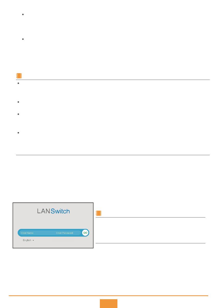
Start the web browser on the computer, enter https://192.168.1.253 in the address box, and press
Enter to display the initial login page. The default username and password are available in S Series
Switches Default Usernames and Passwords. If you have not obtained the access permission of the
document, see Help on the website to find out how to obtain it.
Step 2
Step 3
9
Configure the switch. The web-based configuration page provides basic and optional
configuration items. The basic configuration enables you to log in to the switch using the web
system, and the optional configuration enables you to log in to the switch using Telnet or
STelnet. Only parameters for the basic configuration are described below. For details about the
optional configuration and more information about the product, see the
for your switch on the Huawei support website.
Step 4
Configuration Guide
Users can log in to a device for the first time using the web system only when the device is in factory default
state. In this case, do not log in to the device through the console interface, because any operation on the console
interface leads to the failure of the first login using the web system.
If you do not save the configuration in 10 minutes after entering the initial configuration mode, the system will
exit from this mode and restore the factory settings.
If the device in the factory settings has just started or has been configured through the console interface when
users press and hold down the MODE button for 6 seconds, the device may fail to enter the initial configuration
state. When all indicators blink fast for 10s, the device restores to the factory default state.
If you have logged in to the device for the first time by holding down the MODE button for 6 seconds or longer
and saved the configuration, default configurations of the ETH management interface are cleared and you cannot
log in to the device for the first time through the ETH management interface. You are advised to preferentially log
in to the device for the first time through the ETH management interface.
NOTE
You can directly connect the PC to the ETH management interface or press and hold down the
MODE button to log in to the device through the web system for the first time:
For a device with the ETH management interface, you can directly connect the PC to the ETH
management interface to log in to the device through the web system for the first time.
For a device with the MODE button, you can press and hold down the MODE button to log in to
the device through the web system for the first time.
The following series switches (running V200R012C00 or a later version) support first login through
the web system by directly connecting the PC to the ETH management interface:
S5700S-X-LI, S5710-X-LI, S5720-SI, S5720S-SI, S5720-EI (only the models with the ETH interface),
S5720-HI, S5730, S5730S, S5731, S5731S, S5732, S5735 (only the models with the ETH interface),
S5735S (only the models with the ETH interface), S5736, S6720, S6720S, S6730 except (S6730-H-V2),
and S6730S.
The following series switches support first login through the web system by pressing and holding
down the MODE button:
S2720, S2750, S2730S, S5700-LI, S5700S-LI, S5720-LI, S5720S-LI, S5710-X-LI, S5720-SI, S5720S-SI,
S5720-EI (only the models with the MODE button), S5720-HI, S5730, S5730S, S5731, S5731S,
S5732, S5735, S5735S, S5736, S6720 (only the models with the MODE button), S6720S (only the
models with the MODE button), and S6730 (only the models with the MODE button).
To support this function, the S2750, S5700-LI, S5700S-LI, and S5720-HI must run V200R007C00 or
a later version.
The following series switches do not support first login using the web system:
S2700-SI, S2700-EI, S2710-SI, S3700, S5710-C-LI, S5700-SI, S5700-EI, S5710-EI, S5700-HI,
S6700-EI, S6730-H-V2, and S5720-EI that does not provide a MODE button (S5720-50X-EI-AC,
S5720-50X-EI-DC, S5720-50X-EI-46S-AC, S5720-50X-EI-46S-DC)
You can use console ports to log in to the switches that do not support first login using the web
system for the first time. For details, see 9.2 Using the Console Port for the First Login.
If the web pages cannot be displayed normally, your web browser may need an upgrade. For details
about the web browser requirements, see the
Web-based Configuration Guide
of the switch.
The login page may dier slightly in dierent versions.
Hold down the MODE button to log in to the device for the first time.
If all interfaces on the device are optical interfaces, you need to connect the PC to the management
interface using network cables. Press and hold down the MODE button for 6 seconds or longer. When
all indicators on the device are steady green, the device enters the initial configuration mode, and the
default IP address configured for the ETH management interface of the device is 192.168.1.253/24.
If the device has Ethernet interfaces, connect the PC to any Ethernet interface excluding the
ETH management interface using network cables. Press and hold down the MODE button for 6
seconds or longer. When all indicators on the device are steady green, the device enters the
initial configuration mode, and the default IP address configured for Vlanif1 of the device is
192.168.1.253/24.
(Mode 2)
Configuration Item
Management IP Address
Mask
Old Password
WEB User Password
Confirm Password
WEB User Level
Description
Mandatory. Enter the management IP address of the switch, in dotted decimal notation.
Mandatory. Select a subnet mask from the drop-down list box.
Mandatory. Enter the old password for the default web user.
Mandatory. Enter a new password for the default web user.
To ensure password strength, the password must contain at least two types of the following:
lowercase letters, uppercase letters, digits, and special characters (such as ! $ # %), and
cannot contain any space or single quotation mark.
Mandatory. Enter the new password again.
Optional. Select a user level from the drop-down list box. The user of level 3 or higher
has management rights.
Click Apply to save the configuration. When you exit from the initial login page, either of the
following situations will occur depending on the management IP address you configured:
Step 5
If the management IP address is in the same network segment as 192.168.1.253/24, the system jumps to
the web login page directly.
If the management IP address is not in the same network segment as 192.168.1.253/24, you cannot log in
to the switch again using the web system. You need to configure another IP address for your computer to
make the computer and switch reachable from each other.
The Quick Config function has been added to the web EasyOperation edition since V200R010. You can quickly
finish the configurations of VLAN isolation and interconnection by selecting the Switching and Routing options.
Now, you can log in to the switch using the web system, Telnet, or STelnet to maintain the switch.
10
9.2 Using the Console Port for the First Login
The S5700-LI, S5700S-LI, S5710-EI, S5720-EI and S5720-HI series switches also support login
through the Mini USB port. For details about this login method, see the of the
product. This document describes how to log in to the switch through the console port.
In the S5720-EI series, the S5720-50X-EI-AC, S5720-50X-EI-DC, S5720-50X-EI-46S-AC and
S5720-50X-EI-46S-DC models do not have a Mini USB port.
The console cable is not delivered with the switch and needs to be separately purchased if needed.
The display information may dier on dierent product models.
Install third-party terminal simulation software on the PC by referring to user manual or online
help.
Before You Start
Configuration Guide
Use a console cable to connect the switch to a PC.
Start the terminal simulation software, create a connection, select a serial port, and set communication
parameters in consistent with the default configuration of the switch's console port, as listed below:
Step 1
Step 2
Login Procedure
Transmission rate: 9600
Data bit (B): 8
In V200R020C00 and later versions, the
switch does not have a default console port
login password. You need to set a password
when you log in to the switch through the
console port for the first time.
NOTE
11
Copyright © Huawei Technologies Co., Ltd. 2021. All rights reserved.
No part of this document may be reproduced or
transmitted in any form or by any means without prior
written consent of Huawei Technologies Co., Ltd.
and other Huawei trademarks are trademarks
of Huawei Technologies Co., Ltd.
All other trademarks and trade names
mentioned in this document are the property
of their respective holders.
Supplier’s Declaration of Conformity (SDoC)
Unique Identifier: trade name: HUAWEI; product name: Switch;
model number: S2700&3700&5700&6700 series switches
Responsible Party- U.S. Contact Information
Huawei Technologies USA Inc.
5700 Tennyson Parkway, Suite 500
Plano, Texas 75024
Main: 214-919-6000 / TAC Hotline: 877-448-2934
FCC Compliance Statement ( for products subject to Part 15)
This device complies with part 15 of the FCC Rules. Operation is subject to
the following two conditions: (1) This device may not cause harmful
interference, and (2) this device must accept any interference received,
including interference that may cause undesired operation.
You can run commands to configure the device. Enter a question mark (?) whenever you need help. For
more information, see the for your switch on the Huawei support website.
Press Enter in subsequent steps until the following information is displayed on the terminal
simulation software, and then enter a password. The default username and password are available
in S Series Switches Default Usernames and Passwords. If you have not obtained the access
permission of the document, see Help on the website to find out how to obtain it.
Step 3
Login authentication
Username:admin
Password:
Warning: The default password poses security risks.
The password needs to be changed. Change now? [Y/N]: y
Please enter old password:
Please enter new password:
Please confirm new password:
The password has been changed successfully
<HUAWEI>
The password entered in interactive mode is not displayed on the screen.
If you do not change the authentication mode and password after entering the user view, the
authentication password used for next login is the one configured during the first login.
Log in to Huawei enterprise technical support website (https://support.huawei.com/enterprise),
and select a specific product model and version to find its documentation.
Log in to Huawei enterprise support community
(https://forum.huawei.com/enterprise/en/index.html) and post your questions in the
community.
10 Obtaining Product Documentation and Technical Support
Trademarks and Permissions
Huawei Enterprise
Technical Support
Qualification Card
PASS
Configuration Guide
Open Source Software Notice
The Open Source Software Notice lists notices on open source software components used by the
product. Visit Huawei enterprise technical support website for the Open Source Software Notice.
Parity bit: None
Stop bit (S): 1
Flow control mode: None
  • Page 1 1
  • Page 2 2
  • Page 3 3
  • Page 4 4
  • Page 5 5
  • Page 6 6
  • Page 7 7
  • Page 8 8
  • Page 9 9
  • Page 10 10
  • Page 11 11
  • Page 12 12

Huawei S2700 User guide

Type
User guide

Huawei S2700 series switches are ideal for building enterprise networks, data centers, and campus networks. They provide a variety of features, including:

  • High-speed switching: Huawei S2700 switches offer wire-speed switching for all ports, ensuring smooth data transmission without bottlenecks.

  • Extensive security features: Huawei S2700 switches support a variety of security features, such as access control lists (ACLs), port security, and virtual private networks (VPNs), to protect your network from unauthorized access and attacks.

  • Robust Quality of Service (QoS): Huawei S2700 switches support advanced QoS features, such as traffic classification, scheduling, and congestion control, to ensure that critical traffic is prioritized and delivered with low latency.

Ask a question and I''ll find the answer in the document

Finding information in a document is now easier with AI