Supermicro SuperBlade SBI-7125B-T1 User manual
- Category
- Server barebones
- Type
- User manual

SuperBlade
TM
USER’S MANUAL
Revision 1.0b

The information in this User’s Manual has been carefully reviewed and is believed to be accurate.
The vendor assumes no responsibility for any inaccuracies that may be contained in this document,
makes no commitment to update or to keep current the information in this manual, or to notify any
person or organization of the updates. Please Note: For the most up-to-date version of this
manual, please see our web site at www.supermicro.com.
Super Micro Computer, Inc. ("Supermicro") reserves the right to make changes to the product
described in this manual at any time and without notice. This product, including software, if any,
and documentation may not, in whole or in part, be copied, photocopied, reproduced, translated or
reduced to any medium or machine without prior written consent.
IN NO EVENT WILL SUPERMICRO BE LIABLE FOR DIRECT, INDIRECT, SPECIAL, INCIDENTAL,
SPECULATIVE OR CONSEQUENTIAL DAMAGES ARISING FROM THE USE OR INABILITY TO
USE THIS PRODUCT OR DOCUMENTATION, EVEN IF ADVISED OF THE POSSIBILITY OF
SUCH DAMAGES. IN PARTICULAR, SUPERMICRO SHALL NOT HAVE LIABILITY FOR ANY
HARDWARE, SOFTWARE, OR DATA STORED OR USED WITH THE PRODUCT, INCLUDING THE
COSTS OF REPAIRING, REPLACING, INTEGRATING, INSTALLING OR RECOVERING SUCH
HARDWARE, SOFTWARE, OR DATA.
Any disputes arising between manufacturer and customer shall be governed by the laws of Santa
Clara County in the State of California, USA. The State of California, County of Santa Clara shall
be the exclusive venue for the resolution of any such disputes. Super Micro's total liability for
all claims will not exceed the price paid for the hardware product.
FCC Statement: This equipment has been tested and found to comply with the limits for a Class
A digital device pursuant to Part 15 of the FCC Rules. These limits are designed to provide
reasonable protection against harmful interference when the equipment is operated in a commercial
environment. This equipment generates, uses, and can radiate radio frequency energy and, if not
installed and used in accordance with the manufacturer’s instruction manual, may cause harmful
interference with radio communications. Operation of this equipment in a residential area is likely
to cause harmful interference, in which case you will be required to correct the interference at your
own expense.
WARNING: Handling of lead solder materials used in this
product may expose you to lead, a chemical known to
the State of California to cause birth defects and other
reproductive harm.
Unless you request and receive written permission from Super Micro Computer, Inc., you may not
copy any part of this document.
Information in this document is subject to change without notice. Other products and companies
referred to herein are trademarks or registered trademarks of their respective companies or mark
holders.
Copyright © 2007 by Super Micro Computer Inc.
All rights reserved.
Printed in the United States of America
Manual Revision: 1.0b
Release Date: December 6, 2007

iii
Preface
Preface
About This Manual
This manual is written for professional system integrators, Information Technology
professionals and technicians. It provides information for the installation and use
of Supermicro's SuperBlade system. Installation and maintenance should be per-
formed by experienced professionals only.
Manual Organization
Chapter 1: Overview
The fi rst chapter provides a checklist of the main components included with the
blade system and describes the main features of the mainboard and enclosure. Also
included is a section that describes how to perform common tasks on the system.
Chapter 2: System Safety
You should familiarize yourself with this chapter for a general overview of safety
precautions that should be followed when installing and servicing the SuperBlade.
Chapter 3: Rack Install
Refer here for details on the installing the SuperBlade system into a rack.
Chapter 4: Blade System Modules
This chapter covers the various modules that install into the blade enclosure.
Chapter 5: System Components
Chapter 5 covers the components that make up a blade module (such as the
mainboard, processors, memory and hard drives) and the system power supplies.
Chapter 6: Software and RAID
This chapter covers the operating system installation options and the blade man-
agement software packages that are included with the system. Also refer to this
chapter for the procedure on setting up a RAID array.
Appendix A: Web-based Management Utility
Appendix B: BIOS POST Codes and Messages
Appendix C: BIOS
Appendix D: HCA Mezzanine Card
Appendix E: Gigabit Switch Features
Appendix F: System Specifi cations

iv
Table of Contents
Chapter 1 Introduction
1-1 Overview ......................................................................................................... 1-1
1-2 Blade Module Features ................................................................................... 1-2
Processors ...................................................................................................... 1-2
Memory ........................................................................................................... 1-2
Storage ............................................................................................................ 1-3
Density ........................................................................................................... 1-3
1-3 Blade Enclosure Features ............................................................................... 1-3
Power .............................................................................................................. 1-3
Middle Plane ................................................................................................... 1-3
LEDs ................................................................................................................ 1-4
Enclosure Cooling ........................................................................................... 1-4
1-4 Power Supply Features ................................................................................... 1-5
Power Supply Modules ................................................................................... 1-5
Power Cord ................................................................................................ 1-5
Power Supply Failure ................................................................................. 1-5
1-5 Special Design Features ................................................................................. 1-6
Operating System Support .............................................................................. 1-6
Computing Density/Power ............................................................................... 1-6
High-Effi ciency Power Supplies ...................................................................... 1-6
1-7 Contacting Supermicro .................................................................................... 1-7
Chapter 2 System Safety
2-1 Electrical Safety Precautions .......................................................................... 2-1
2-2 General Safety Precautions ............................................................................ 2-2
2-3 ESD Precautions ............................................................................................. 2-3
2-4 Operating Precautions .................................................................................... 2-3
Chapter 3 Setup and Installation
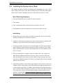
3-1 Overview ............................................................................................................. 3-1
3-2 Unpacking the System .................................................................................... 3-1
3-3 Preparing for Setup ......................................................................................... 3-1
Choosing a Setup Location ............................................................................. 3-1
Rack Precautions ............................................................................................ 3-2
Server Precautions .......................................................................................... 3-2
Rack Mounting Considerations ....................................................................... 3-3
Ambient Operating Temperature ................................................................ 3-3
SuperBlade User's Manual

Preface
v
Reduced Airfl ow ......................................................................................... 3-3
Mechanical Loading ................................................................................... 3-3
Circuit Overloading ..................................................................................... 3-3
Reliable Ground ......................................................................................... 3-3
3-4 Installing the System into a Rack ................................................................... 3-4
Rack Mounting Hardware ............................................................................... 3-4
Installation ....................................................................................................... 3-4
Chapter 4 Blade System Modules
4-1 CMM: Chassis Management Module .............................................................. 4-2
Module Redundancy ....................................................................................... 4-3
Master/Slave Modules ................................................................................ 4-3
Master/Slave Determination ....................................................................... 4-3
Installing the Module ....................................................................................... 4-4
Removing the Module ..................................................................................... 4-4
CMM Functions ............................................................................................... 4-4
Local KVM .................................................................................................. 4-4
Remote KVM over IP ................................................................................. 4-5
Remote Storage (Virtual Media) ................................................................. 4-5
Serial Over LAN (SOL) .............................................................................. 4-5
Monitoring Functions .................................................................................. 4-5
CMM Switches and Buttons ............................................................................ 4-6
USB Switch ................................................................................................ 4-6
Reset Button ............................................................................................... 4-6
Firmware ......................................................................................................... 4-6
4-2 Infi niBand Module ........................................................................................... 4-7
Installing the Module ....................................................................................... 4-7
Removing the Module ..................................................................................... 4-8
Infi niBand Switch LEDs .................................................................................. 4-8
Module Power LED .................................................................................... 4-8
Module Status LED .................................................................................... 4-9
Port LEDs ................................................................................................... 4-9
Confi guring the Infi niBand Module .................................................................. 4-9
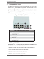
4-3 GbE (Ethernet) Switch .................................................................................. 4-10
Installing the Module ..................................................................................... 4-10
Removing the Module ....................................................................................4-11
GbE Switch LEDs ......................................................................................... 4-12
Module Initiation OK LED ......................................................................... 4-12
Module Fault LED .................................................................................... 4-12

vi
Ethernet Port Status LEDs ....................................................................... 4-12
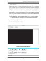
Confi guring the GbE Switch .......................................................................... 4-13
Web-based Management Utility/IPMI ....................................................... 4-13
Network Connection/Login ....................................................................... 4-13
Address Defaults ...................................................................................... 4-13
Command Line ......................................................................................... 4-14
Firmware ....................................................................................................... 4-14
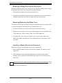
4-4 Blade Modules .............................................................................................. 4-15
Powering up a Blade Unit ............................................................................. 4-15
Powering down a Blade Unit ........................................................................ 4-15
Removing a Blade Unit from the Enclosure ................................................. 4-16
Removing/Replacing the Blade Cover .......................................................... 4-16
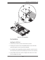
Installing a Blade Unit into the Enclosure ..................................................... 4-16
4-5 Double-Wide Modules ................................................................................... 4-18
Chapter 5 System Components
5-1 Blade Unit Features ........................................................................................ 5-1
Control Panel .................................................................................................. 5-1
Power Button .............................................................................................. 5-1
KVM Button ................................................................................................ 5-3
KVM Connector .......................................................................................... 5-3
Power LED ................................................................................................. 5-3
KVM/UID LED ............................................................................................ 5-3
Network LED .............................................................................................. 5-3
System Fault LED ...................................................................................... 5-3
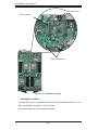
Mainboard ....................................................................................................... 5-4
Jumpers ...................................................................................................... 5-4
CMOS Clear ............................................................................................... 5-4
5-2 Blade Unit Components .................................................................................. 5-6
Processors ...................................................................................................... 5-6
Removing a Processor ............................................................................... 5-6
Installing a Processor ................................................................................. 5-6
Onboard Battery .............................................................................................. 5-7
Memory ........................................................................................................... 5-9
Installing DIMMs ........................................................................................5-9
Memory Support ......................................................................................... 5-9
Hard Disk Drives ............................................................................................5-11
Removing a Hard Drive Carrier ................................................................5-11
Installing a Hard Drive ...............................................................................5-11
SuperBlade User's Manual

Preface
vii
5-3 Power Supplies ............................................................................................. 5-12
Power Supply Modules ................................................................................. 5-12
Power Cord .............................................................................................. 5-12
Power Supply Failure ............................................................................... 5-12
Removing a Power Supply ....................................................................... 5-12
Installing a Power Supply ......................................................................... 5-13
Power Supply Fans ....................................................................................... 5-13
Chapter 6 Software and RAID
6-1 Installing the Operating System ...................................................................... 6-1
Installing with an External USB CD-ROM Drive ............................................. 6-1
Installing via PXE Boot ................................................................................... 6-2
Installing via Virtual Media (Drive Redirection) ............................................... 6-2
6-2 Management Software .................................................................................... 6-2
6-3 Installing the Operating System with RAID ..................................................... 6-3
Preparing for Setup ......................................................................................... 6-3
Changing BIOS Settings ................................................................................. 6-3
Installation ....................................................................................................... 6-4
6-4 RAID Utility Programs ..................................................................................... 6-5
RAID Confi gurations ................................................................................... 6-5
Intel Matrix Storage Manager ......................................................................... 6-5
Creating, Deleting and Resetting RAID Volumes ...................................... 6-5
Adaptec RAID Confi guration Utility ................................................................. 6-9
Managing Arrays ........................................................................................ 6-9
Appendix A Web-based Management Utility
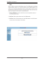
A-1 Network Connection/Login ..............................................................................A-1
Address Defaults .............................................................................................A-2
A-2 Home Page .....................................................................................................A-3
Home Page Controls .......................................................................................A-3
A-3 Main Menu Icons .............................................................................................A-4
Blade System ..................................................................................................A-5
Blade ..........................................................................................................A-5
Power Supply .............................................................................................A-6
Gigabit Switch ............................................................................................A-7
CMM ...........................................................................................................A-8
KVM Console .............................................................................................A-9
SOL Console ............................................................................................ A-11
Virtual Media .................................................................................................A-12
Floppy Disk ...............................................................................................A-12

viii
CD-ROM ................................................................................................... A-13
Drive Redirection ......................................................................................A-14
Options .....................................................................................................A-15
System Health ...............................................................................................A-15
System Event Log ....................................................................................A-15
Alert Settings ............................................................................................A-16
User Management .........................................................................................A-17
Change Password ....................................................................................A-17
Users & Groups ........................................................................................A-18
Permissions ..............................................................................................A-20
User Console ............................................................................................A-21
Keyboard/Mouse ......................................................................................A-24
Device Settings .............................................................................................A-25
Network ....................................................................................................A-25
Dynamic DNS ...........................................................................................A-27
Security .....................................................................................................A-28
Date/Time .................................................................................................A-30
Event Log .................................................................................................A-31
SNMP Settings .........................................................................................A-33
Maintenance .................................................................................................. A-34
Device Information ...................................................................................A-34
Event Log .................................................................................................A-35
Update Firmware ......................................................................................A-36
Unit Reset .................................................................................................A-37
Remote Console .......................................................................................A-37
Remote Console Options .........................................................................A-37
A-4 Log Out .........................................................................................................A-44
Appendix B BIOS POST Codes and Messages
B-1 BIOS POST Messages ...................................................................................B-1
B-2 BIOS POST Codes .........................................................................................B-6
Recoverable POST Errors ..............................................................................B-6
Terminal POST Errors .....................................................................................B-6
Appendix C BIOS
C-1 Introduction ......................................................................................................C-1
System BIOS ...................................................................................................C-1
How To Change the Confi guration Data ........................................................C-1
Starting the Setup Utility .................................................................................C-1
C-2 BIOS Updates .................................................................................................C-2
SuperBlade User's Manual

Preface
Flashing BIOS .................................................................................................C-2
Using the KVM Dongle ...............................................................................C-2
Using the USB Ports on the CMM .............................................................C-2
Using a Floppy Image File .........................................................................C-3
C-3 Running Setup ................................................................................................C-4
C-4 Main BIOS Setup ............................................................................................C-4
Main BIOS Setup Menu ..................................................................................C-4
C-5 Advanced Setup ..............................................................................................C-7
C-6 Security .........................................................................................................C-16
C-7 Boot ...............................................................................................................C-17
C-8 Exit ................................................................................................................C-17
Appendix D HCA Mezzanine Card
D-1 Introduction ......................................................................................................D-1
Overview .........................................................................................................D-1
Product Features .............................................................................................D-1
Required Tools ................................................................................................D-1
Images .............................................................................................................D-1
D-2 Safety Guidelines ............................................................................................D-2
ESD Safety Guidelines ...................................................................................D-2
General Safety Guidelines ..............................................................................D-2
An Important Note to Users ............................................................................D-2
D-3 Installation .......................................................................................................D-3
Components ....................................................................................................D-3
Installation Location ....................................................................................D-4
Card Installation ..............................................................................................D-5
Installing the HCA Card ..............................................................................D-5
Appendix E Gigabit Switch Features
E-1 Port Status ......................................................................................................E-1
Port VLAN ID (PVID) ......................................................................................E-1
Port Confi guration ...........................................................................................E-1
E-2 Statistics ..........................................................................................................E-3
Port Statistics ..................................................................................................E-3
E-3 VLAN ...............................................................................................................E-6
Confi guring a Static VLAN ..............................................................................E-7
E-4 Trunking ..........................................................................................................E-9
E-5 Mirroring ........................................................................................................ E-11
E-6 Quality of Service ..........................................................................................E-12
Priority Queues .............................................................................................E-12
ix

x
List of Figures
Figure 2-1. Installing the Onboard Battery ................................................................. 2-2
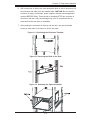
Figure 3-1. Positioning the Enclosure Template ........................................................ 3-5
Figure 3-2. Securing the Rails to the Rack ................................................................ 3-5
Figure 3-3. Attaching the Optional Handles ............................................................... 3-5
Figure 3-4. Enclosure Installed into Rack .................................................................. 3-6
Figure 4-1. Typical Blade System Module Confi guration: Rear View ........................ 4-1
Figure 4-2. Chassis Management Module ................................................................. 4-2
Figure 4-3. USB Switch on Rear of CMM .................................................................. 4-6
Figure 4-4. Infi niBand Module .................................................................................... 4-7
Figure 4-5. GbE (Ethernet) Switch ........................................................................... 4-10
Figure 4-6. Confi guring the GbE Switch .................................................................. 4-14
Figure 4-7. Confi guring the GbE Switch .................................................................. 4-15
Figure 4-8. Inserting a Blade into the Enclosure ..................................................... 4-17
Figure 4-9. Locking the Blade into Position ............................................................. 4-17
Figure 4-10. Horizontal Spacers for Single Bays ..................................................... 4-18
E-7 Rate Control ..................................................................................................E-14
E-8 L2 Management ............................................................................................E-15
E-9 Spanning Tree ...............................................................................................E-17
Bridge Protocol Data Unit (BPDU) ................................................................E-17
Port Transition State .....................................................................................E-18
RSTP Port Roles ......................................................................................E-18
Root Status ...............................................................................................E-19
Bridge Setting ...........................................................................................E-20
RSTP Port Settings ..................................................................................E-20
E-10 IEEE 802.1x ..................................................................................................E-21
Wiring for 802.1x ...........................................................................................E-22
802.1x Confi guration .....................................................................................E-23
E-11 IGMP Snooping .............................................................................................E-24
E-12 SNMP ............................................................................................................E-26
Appendix F System Specifi cations
F-1 Blade Specifi cations ........................................................................................ F-1
F-2 Enclosure Specifi cations ................................................................................. F-2
F-3 Environmental Specifi cations .......................................................................... F-2
F-4 Address Defaults ............................................................................................. F-3
F-5 Optional Components ..................................................................................... F-4
SuperBlade User's Manual

xi
Preface
Figure 4-11a. Modifying for a Double-Wide Module Bay (Steps 1 & 2) .................. 4-19
Figure 4-11b. Modifying for a Double-Wide Module Bay (Steps 3 & 4) .................. 4-20
Figure 5-1. Front View of Blade ................................................................................. 5-2
Figure 5-2. Intel 5000P/ESB2 Chipset: Block Diagram ............................................. 5-4
Figure 5-3. B7DBE Mainboard ................................................................................... 5-5
Figure 5-4. Installing a Processor in a Socket ........................................................... 5-7
Figure 5-5. Installing the Onboard Battery ................................................................. 5-7
Figure 5-6. Exploded View of Blade Module ............................................................. 5-8
Figure 5-7. DIMM Slot Numbering ........................................................................... 5-10
Figure 5-8. Installing DIMM into Memory Slot ......................................................... 5-10
Figure 5-9. Installing a Hard Drive in a Carrier .........................................................5-11
Figure 5-10. Power Cord: C20 (Male End) and C19 (Female End) ........................ 5-13
Figure 5-11. Power Supply Module .......................................................................... 5-14
Figure 6-1. RAID Volumes ......................................................................................... 6-5
Figure 6-2. RAID 0 Volume ........................................................................................ 6-6
Figure 6-3. Select Disk ............................................................................................... 6-6
Figure 6-4. RAID Volume 1 ........................................................................................ 6-7
Figure 6-5. RAID Reset .............................................................................................. 6-8
Figure 6-6. Select Drives for Array Creation ............................................................ 6-10
Figure 6-7. Array Creation ........................................................................................ 6-10
Figure 6-8. Array Assignment ....................................................................................6-11
Figure 6-9. Array Properties ..................................................................................... 6-12
List of Tables
Table 1-1. Summary of Blade Module Features (for SBI-7125B-T1) ......................... 1-2
Table 1-2. Blade Enclosure LED Descriptions ........................................................... 1-4
Table 4-1. Blade System: Module View ..................................................................... 4-1
Table 4-2. CMM Module Interface .............................................................................. 4-2
Table 4-3. CMM Module Features .............................................................................. 4-3
Table 4-4. Infi niBand Module Interface ...................................................................... 4-7
Table 4-5. Infi niBand Module Features ...................................................................... 4-8
Table 4-6. GbE Switch Module Interface ................................................................ 4-10
Table 4-7. GbE Switch Module Features ..................................................................4-11
Table 5-1. Blade Unit Features .................................................................................. 5-1
Table 5-2. Blade Control Panel .................................................................................. 5-2
Table 5-3. Mainboard Layout ..................................................................................... 5-5
Table 5-4. Main Components of Blade Module .......................................................... 5-8

xii
SuperBlade User's Manual
Table 5-5. Populating Memory Slots for Interleaved Operation ............................... 5-10
Table 6-1. RAID Levels ............................................................................................ 6-12
Table E-1. Comparison of Port States .....................................................................E-18
Table E-2. Gigabit Switch Features and Functions ..................................................E-27
Table F-1. Power Supply: Power Calculations (PWS-2K01-BR) ............................... F-4
Table F-2. Power Supply:Power Factor (PWS-2K01-BR) .......................................... F-4

Chapter 1
Introduction
1-1 Overview
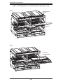
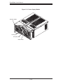
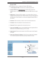
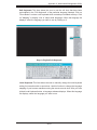
The SuperBlade is a compact self-contained server that connects to a pre-cabled
enclosure which provides power, cooling, management and networking functions.
One enclosure can hold up to ten blade units.
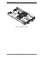
In this manual, "blade system" refers to the entire system (including the enclosure
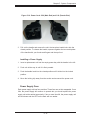
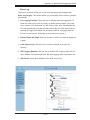
and blades units), "blade" or "blade unit" refers to a single blade module (as shown
in Figure 5-1) and "blade enclosure" is the unit that the blades, power supplies and
modules are housed in. Please refer to our web site for information on operating
systems that have been certifi ed for use with the SuperBlade:
www.supermicro.com/products/superblade/
An example blade system includes:
Blade Enclosure (x1): SBE-710E
Blade Unit (x2): SBI-7125B-T1
Power Supplies (x2 or x4): PWS-2K01-BR
CMM Module (x1): SBM-CMM-001
KVM Cable (x1): CBL-0204L
Dummy Blade Units (x8): MCP-650-00004-0N
Dummy Power Supplies (x2): MCP-650-00001-0N
Dummy CMM Modules (x3): MCP-650-00002-0N
Dummy GbE Switches (x2): MCP-650-00003-0N
Optional components include:
Infi niBand® Switch (x1): SBM-IBS-001
GbE Switches (x1 or x2): SBM-GEM-001
•
•
•
•
•
•
•
•
•
•
•
Chapter 1: Introduction
1-1

1-2
SuperBlade User's Manual
1-2 Blade Module Features
The following table lists the main features of a blade module. See the preceeding
section for components typically included in a blade system and other optional
components. Details on the blade modules may be found in Chapter 5.
Table 1-1. Summary of Blade Module Features (for SBI-7125B-T1)
Processors
Supports single or dual 771-pin Intel® Xeon® 5300/5100/5000 series processors (per blade module)
Memory
Supports up to 32 GB of ECC DDR2-667/533 FDB (Fully Buffered DIMMs) in 8 DIMM slots (per blade module)
Storage
One or two 3.5" hot-plug SATA hard disk drives per blade module
Blades per Enclosure
10 maximum
Blades per Rack
60 maximum (6 blade enclosures per standard 42U rack)
Processors
Each blade module supports single or dual 771-pin Intel Xeon 5300/5100/5000
series processors at a FSB speed of 1333/1066/667 MHz. Refer to the Supermicro
web site for a complete listing of supported processors (http://www.supermicro.
com/products/superblade.) Please note that you will need to check the detailed
specifi cations of a particular blade module for a list of the CPUs it supports.
Memory
Each blade module has eight 240-pin DIMM sockets that can support up to 32 GB
of ECC FBD (Fully Buffered DIMM) DDR2-667 or DDR2-533 SDRAM. Memory is
interleaved, which requires modules of the same size and speed to be installed in
pairs. Please refer to the Supermicro web site for a list of supported memory (www.
GbE Pass Through Modules (x1 or x2): SBM-GEM-002
Extra CMM Module for redundancy (x1): (SBM-CMM-01)
Additional modules will periodically become available. Please refer to http://www.
supermicro.com/products/superblade for the most current list of modules available
for the SuperBlade.
Blade systems install into standard racks. Up to six blade systems may be installed
into a 19" industry standard 42U rack.
•
•

1-3
Chapter 1: Introduction
1-3 Blade Enclosure Features
Supermicro's SBE-710E blade enclosure was designed to house up to 10 blade
units and accommodate either two or four power supplies. The enclosure back-
plane allows the blade units to share certain functions such as power, cooling and
networking.
The following is a general outline of the main features of the SBE-710E blade
server enclosure.
Power
The SBE-710E enclosure typically features a 2000W power system composed of
two active power supply modules. An alternate confi guration (and required for a
10-blade system) features a total of four power supply modules for three active and
one backup. (This power redundancy feature allows you to replace a failed power
module while the backup module takes over to keep the system running). You must
have either two or four power supply modules installed in the blade enclosure (four
is recommended in a 10-blade system).
Logic on a blade motherboard calculates the amount of power it will require based
on the number of processors and memory installed. If the power supplies cannot
supply enough power for any blade unit, that unit will not power up.
Middle Plane
The middle plane integrates the various functions of the blades, the Gigabit (GbE)
switch(es), the Chassis Management Module (CMM) and the Infi niBand switch.
supermicro.com/products/superblade). The detailed specifi cations for a blade mod-
ule will contain a link to a list of recommended memory sizes and manufacturers.
Storage
A blade module can support either one or two 3.5-inch SATA (Serial ATA) hard
disk drives.
Density
A maximum of 10 blade modules may be installed into a single blade enclosure.
Each blade enclosure is a 7U form factor, so a standard rack may accommodate
up to 60 blade modules, or the equivalent of 60 1U servers. With the inclusion of 6
CMM modules, 6 Gigabit Ethernet switches and 6 Infi niBand switches, this would
occupy a 72U space in a conventional 1U server confi guration.

1-4
SuperBlade User's Manual
These devices all connect to the middle plane through high density connectors that
provide both signals and power. This type of confi guration reduces the amount of
system cabling and simplifi es the task of setting up the system. To increase system
reliability, the middle plane contains no active components.
LEDs
Two LEDs are located at the right top of the enclosure above blade bay #10. The
left LED provides Power Status information and the right LED is the Fault LED, as
described in Table 1-2.
For overheat problems, check that there are no obstructions (such as poorly routed
cables), check that all fans are operating normally and make sure the ambient
room temperature is not too warm (refer to Appendix D for the maximum operating
temperature). You can also use either of the blade management software utilities
to increase the fan speed and maximize system cooling.
In the event of a power overload, you will have to add additional power supply mod-
ules to take up the load. Otherwise, you will not be able to power up all the blade
modules. (EEPROMs on each blade motherboard calculate the load to determine if
the power supplies can adequately handle the total system confi guration.)
Enclosure Cooling
The cooling for the entire blade system is provided by the fans in the power sup-
ply modules. The 2000W power supply modules have four fans per module. If a
power supply fails, its fans will continue to operate to provide continuous cooling.
For this reason, a failed power supply should remain installed in the enclosure until
a replacement unit is ready.
Table 1-2. Blade Enclosure LED Descriptions
LED State Indication
Power Status LED
(left LED)
NA (off) Standby state
Green Power On
Green (fl ashing) Power Overload
Red Power supply failure
Fault LED
(right LED)
Yellow Over temperature state in switch module (GbE, IB)
Flashing Yellow Fan failure
Off Normal

1-5
Chapter 1: Introduction
1-4 Power Supply Features
The SuperBlade enclosure comes standard with one CMM module and either two
or four power supplies. Information on the power supplies is summarized below.
See the Chapter 4 for details on the CMM module and Section 5-3 for details on
the power supplies.
If you install only two power supplies in the enclosure, they should be installed in
the lower rather than the upper power bays. The reason for this counter-intuitive
installation is that the power supplies in the lower bays provide increased airfl ow
across the memory modules within each blade module.
Power Supply Modules
Each power supply module has its own power cord. Four modules are required
when the full complement of 10 blade units are installed into an enclosure. An LED
on the back of a power supply will be red when AC power is present and green
when the power is on.
Supermicro's high-effi ciency blade system power supplies deliver continuous
redundant power at 90%+ peak effi ciency. Each power supply module includes a
management module that monitors the power supplies and the power enclosure
Power Cord
Each power supply module has a C-20 type socket (IEC-60320-C20) for AC power
and the power cord must have a C-19 type connector (IEC-60320-C19) to connect
to the power supply. A plastic locking clip partially covering the socket was designed
to prevent the power supply module from being removed with the power cord still
connected. Refer to Appendix E for power/amperage calculation tables.
Power Supply Failure
If a power supply or a fan in a power supply fails, the system management software
will notify you of the situation. In either case, you will need to replace the power
supply module with another identical one. Please note that if a power supply fails,
its fans will continue to operate to provide system cooling. For this reason, a failed
power supply should remain installed in the enclosure until a replacement unit is
ready.See Section 5-3 for the procedure on replacing power supplies.

1-6
SuperBlade User's Manual
1-5 Special Design Features
Supermicro's SuperBlades offer special design features, some of which no other
blade server can duplicate. These features give you extraordinary fl exibility in con-
fi guring a blade system for your own particular needs.
Operating System Support
Both Microsoft Windows and Linux operating systems are supported by Super-
Blades. Furthermore, you may have different operating systems running on different
blade units within the same blade enclosure.
Computing Density/Power
Each SuperBlade mainboard supports two quad-core processors and up to 32 GB
of main memory. This translates to 80 processors (cores) and 320 GB of memory
per enclosure or 480 processors (cores) and 1.92 TB of memory for a full rack.
High-Effi ciency Power Supplies
A reliable source of power is critical in server systems and even more so in a blade
system, where up to ten systems (blades) share the same power source. Super-
Blade power supplies have been designed to operate at a 90%+ peak effi ciency
and provide redundancy with a backup unit that activates automatically when any
other power supply fails. Using high-effi ciency power supplies results in a measur-
able reduction in energy consumption and generated heat.

1-7
Chapter 1: Introduction
1-7 Contacting Supermicro
Headquarters
Address: Super Micro Computer, Inc.
980 Rock Ave.
San Jose, CA 95131 U.S.A.
Tel: +1 (408) 503-8000
Fax: +1 (408) 503-8008
Email: [email protected] (General Information)
[email protected] (Technical Support)
Web Site: www.supermicro.com
Europe
Address: Super Micro Computer B.V.
Het Sterrenbeeld 28, 5215 ML
's-Hertogenbosch, The Netherlands
Tel: +31 (0) 73-6400390
Fax: +31 (0) 73-6416525
Email: [email protected] (General Information)
[email protected] (Technical Support)
[email protected] (Customer Support)
Asia-Pacifi c
Address: Super Micro, Taiwan
4F, No. 232-1, Liancheng Rd.
Chung-Ho 235, Taipei County
Taiwan, R.O.C.
Tel: +886-(2) 8226-3990
Fax: +886-(2) 8226-3991
Web Site: www.supermicro.com.tw
Technical Support:
Email: [email protected]
Tel: 886-2-8228-1366, ext.132 or 139

1-8
SuperBlade User's Manual
Notes
Page is loading ...
Page is loading ...
Page is loading ...
Page is loading ...
Page is loading ...
Page is loading ...
Page is loading ...
Page is loading ...
Page is loading ...
Page is loading ...
Page is loading ...
Page is loading ...
Page is loading ...
Page is loading ...
Page is loading ...
Page is loading ...
Page is loading ...
Page is loading ...
Page is loading ...
Page is loading ...
Page is loading ...
Page is loading ...
Page is loading ...
Page is loading ...
Page is loading ...
Page is loading ...
Page is loading ...
Page is loading ...
Page is loading ...
Page is loading ...
Page is loading ...
Page is loading ...
Page is loading ...
Page is loading ...
Page is loading ...
Page is loading ...
Page is loading ...
Page is loading ...
Page is loading ...
Page is loading ...
Page is loading ...
Page is loading ...
Page is loading ...
Page is loading ...
Page is loading ...
Page is loading ...
Page is loading ...
Page is loading ...
Page is loading ...
Page is loading ...
Page is loading ...
Page is loading ...
Page is loading ...
Page is loading ...
Page is loading ...
Page is loading ...
Page is loading ...
Page is loading ...
Page is loading ...
Page is loading ...
Page is loading ...
Page is loading ...
Page is loading ...
Page is loading ...
Page is loading ...
Page is loading ...
Page is loading ...
Page is loading ...
Page is loading ...
Page is loading ...
Page is loading ...
Page is loading ...
Page is loading ...
Page is loading ...
Page is loading ...
Page is loading ...
Page is loading ...
Page is loading ...
Page is loading ...
Page is loading ...
Page is loading ...
Page is loading ...
Page is loading ...
Page is loading ...
Page is loading ...
Page is loading ...
Page is loading ...
Page is loading ...
Page is loading ...
Page is loading ...
Page is loading ...
Page is loading ...
Page is loading ...
Page is loading ...
Page is loading ...
Page is loading ...
Page is loading ...
Page is loading ...
Page is loading ...
Page is loading ...
Page is loading ...
Page is loading ...
Page is loading ...
Page is loading ...
Page is loading ...
Page is loading ...
Page is loading ...
Page is loading ...
Page is loading ...
Page is loading ...
Page is loading ...
Page is loading ...
Page is loading ...
Page is loading ...
Page is loading ...
Page is loading ...
Page is loading ...
Page is loading ...
Page is loading ...
Page is loading ...
Page is loading ...
Page is loading ...
Page is loading ...
Page is loading ...
Page is loading ...
Page is loading ...
Page is loading ...
Page is loading ...
Page is loading ...
Page is loading ...
Page is loading ...
Page is loading ...
Page is loading ...
Page is loading ...
Page is loading ...
Page is loading ...
Page is loading ...
Page is loading ...
Page is loading ...
Page is loading ...
Page is loading ...
Page is loading ...
Page is loading ...
Page is loading ...
Page is loading ...
Page is loading ...
Page is loading ...
Page is loading ...
Page is loading ...
Page is loading ...
Page is loading ...
Page is loading ...
Page is loading ...
Page is loading ...
Page is loading ...
Page is loading ...
Page is loading ...
Page is loading ...
Page is loading ...
Page is loading ...
Page is loading ...
Page is loading ...
Page is loading ...
Page is loading ...
Page is loading ...
Page is loading ...
Page is loading ...
Page is loading ...
-
 1
1
-
 2
2
-
 3
3
-
 4
4
-
 5
5
-
 6
6
-
 7
7
-
 8
8
-
 9
9
-
 10
10
-
 11
11
-
 12
12
-
 13
13
-
 14
14
-
 15
15
-
 16
16
-
 17
17
-
 18
18
-
 19
19
-
 20
20
-
 21
21
-
 22
22
-
 23
23
-
 24
24
-
 25
25
-
 26
26
-
 27
27
-
 28
28
-
 29
29
-
 30
30
-
 31
31
-
 32
32
-
 33
33
-
 34
34
-
 35
35
-
 36
36
-
 37
37
-
 38
38
-
 39
39
-
 40
40
-
 41
41
-
 42
42
-
 43
43
-
 44
44
-
 45
45
-
 46
46
-
 47
47
-
 48
48
-
 49
49
-
 50
50
-
 51
51
-
 52
52
-
 53
53
-
 54
54
-
 55
55
-
 56
56
-
 57
57
-
 58
58
-
 59
59
-
 60
60
-
 61
61
-
 62
62
-
 63
63
-
 64
64
-
 65
65
-
 66
66
-
 67
67
-
 68
68
-
 69
69
-
 70
70
-
 71
71
-
 72
72
-
 73
73
-
 74
74
-
 75
75
-
 76
76
-
 77
77
-
 78
78
-
 79
79
-
 80
80
-
 81
81
-
 82
82
-
 83
83
-
 84
84
-
 85
85
-
 86
86
-
 87
87
-
 88
88
-
 89
89
-
 90
90
-
 91
91
-
 92
92
-
 93
93
-
 94
94
-
 95
95
-
 96
96
-
 97
97
-
 98
98
-
 99
99
-
 100
100
-
 101
101
-
 102
102
-
 103
103
-
 104
104
-
 105
105
-
 106
106
-
 107
107
-
 108
108
-
 109
109
-
 110
110
-
 111
111
-
 112
112
-
 113
113
-
 114
114
-
 115
115
-
 116
116
-
 117
117
-
 118
118
-
 119
119
-
 120
120
-
 121
121
-
 122
122
-
 123
123
-
 124
124
-
 125
125
-
 126
126
-
 127
127
-
 128
128
-
 129
129
-
 130
130
-
 131
131
-
 132
132
-
 133
133
-
 134
134
-
 135
135
-
 136
136
-
 137
137
-
 138
138
-
 139
139
-
 140
140
-
 141
141
-
 142
142
-
 143
143
-
 144
144
-
 145
145
-
 146
146
-
 147
147
-
 148
148
-
 149
149
-
 150
150
-
 151
151
-
 152
152
-
 153
153
-
 154
154
-
 155
155
-
 156
156
-
 157
157
-
 158
158
-
 159
159
-
 160
160
-
 161
161
-
 162
162
-
 163
163
-
 164
164
-
 165
165
-
 166
166
-
 167
167
-
 168
168
-
 169
169
-
 170
170
-
 171
171
-
 172
172
-
 173
173
-
 174
174
-
 175
175
-
 176
176
-
 177
177
-
 178
178
-
 179
179
-
 180
180
-
 181
181
-
 182
182
-
 183
183
-
 184
184
-
 185
185
-
 186
186
-
 187
187
-
 188
188


Supermicro SuperBlade SBI-7125B-T1 User manual
- Category
- Server barebones
- Type
- User manual
Ask a question and I''ll find the answer in the document
Finding information in a document is now easier with AI
Related papers
-
Supermicro GEM002 User manual
-
Supermicro SBI-7126TG User manual
-
-
-
-
SUPER MICRO Computer SBA-7222G-T2 User manual
-
Supermicro SuperBlade SBA-7121M-T1 Quick start guide
-
Supermicro Superblade SBM-XEM-002 User manual
-
-
Other documents
-
 Yottamaster DF4RU3 User guide
-
 Cables Direct NLKVM-CABUSB Datasheet
-
Gigabyte R151-Z30 Installation guide
-
Digitus DA-70520 Datasheet
-
Sitecom LN-350 Datasheet
-
Definitive Technology Studio 3D Mini Operating instructions
-
-
Verbatim External Hard Drive NAS User manual
-
 Supero SBA-7142G-T4 User manual
-
NEC SigmaBlade AD106a User guide


