Page is loading ...

Skip to content
Manuals+
User Manuals Simplified.
AcuityBrands DSL3 Emergency
Lighting Unit Instruction Manual
Home » AcuityBrands » AcuityBrands DSL3 Emergency Lighting
Unit Instruction Manual
Contents hide
1 IMPORTANT SAFETY INSTRUCTIONS
2 DSL3
2.1 EMERGENCY LIGHTING UNIT
3 IMPORTANT SAFEGUARDS
3.1 READ AND FOLLOW ALL SAFETY INSTRUCTIONS
4 INSTALLATION and MOUNTING
4.1 MOUNTING BRACKET
4.2 SURFACE CONDUIT MOUNTING
5 TESTING and MAINTENANCE
5.1 Manual testing:
5.2 Self-Diagnostics (SDRT feature)
5.3 Postponing a self-test:
5.4 Cancelling emergency operation:
5.5 Load-Learning feature:
5.6 Clearing a failure indication:
5.7 IMPORTANT BATTERY INFORMATION:
5.8 Unit Status Indications
5.9 Remote Test (SDRT): (RTKITHLP sold separately)
6 MAINTENANCE
6.1 TO OPEN THE UNIT:
6.2 BATTERY REPLACEMENT:
6.3 LAMP REPLACEMENT
6.4 CHARGER BOARD REPLACEMENT
7 LAMP AIMING and WIRING DIAGRAM
7.1 LAMP AIMING
7.2 WIRING DIAGRAM
8 Documents / Resources
8.1 References
9 Related Posts
IMPORTANT SAFETY INSTRUCTIONS
READ AND FOLLOW ALL SAFETY INSTRUCTIONS! SAVE THESE INSTRUCTIONS AND DELIVER TO OWNER AFTER
INSTALLATION
To reduce the risk of death, personal injury or property damage from fire, electric shock, falling parts, cuts/abrasions, and
other hazards please read all warnings and instructions included with and on the fixture box and all fixture labels.
Before installing, servicing, or performing routine maintenance upon this equipment, follow these general precautions.
Installation and service of luminaires should be performed by a qualified licensed electrician.
Maintenance of the luminaires should be performed by person(s) familiar with the luminaires’ construction and operation
and any hazards involved. Regular fixture maintenance programs are recommended.
It will occasionally be necessary to clean the outside of the refractor/lens. Frequency of cleaning will depend on ambient dirt
level and minimum light output which is acceptable to user. Refractor/lens should be washed in a solution of warm water
and any mild, non-abrasive household detergent, rinsed with clean water and wiped dry. Should optical assembly become
dirty on the inside, wipe refractor/lens and clean in above manner, replacing damaged gaskets as necessary.
DO NOT INSTALL DAMAGED PRODUCT! This luminaire has been properly packed so that no parts should have been
damaged during transit. Inspect to confirm. Any part damaged or broken during or after assembly should be replaced.

Recycle: For information on how to recycle LED electronic products, please visit www.epa.gov.
These instructions do not purport to cover all details or variations in equipment nor to provide every possible contingency to
meet in connection with installation, operation, or maintenance. Should further information be desired or should particular
problems arise which are not covered sufficiently for the purchaser’s or owner’s purposes, this matter should be referred to
Acuity Brands Lighting, Inc.
WARNING RISK OF ELECTRIC SHOCK
Disconnect or turn off power before installation or servicing.
Verify that supply voltage is correct by comparing it with the luminaire label information.
Make all electrical and grounded connections in accordance with the National Electrical Code (NEC) and any applicable
local code requirements.
All wiring connections should be capped with UL approved recognized wire connectors.
CAUTION RISK OF INJURY
Wear gloves and safety glasses at all times when removing luminaire from carton, installing, servicing or performing
maintenance.
Avoid direct eye exposure to the light source while it is on.
WARNING RISK OF BURN
Allow lamp/fixture to cool before handling. Do not touch enclosure or light source.
Do not exceed maximum wattage marked on luminaire label.
Follow all manufacturer’s warnings, recommendations and restrictions for: driver type, burning position, mounting
locations/methods, replacement and recycling.
CAUTION RISK OF FIRE
Keep combustible and other materials that can burn, away from lamp/lens.
Do not operate in close proximity to persons, combustible materials or substances affected by heat or drying.
CAUTION: RISK OF PRODUCT DAMAGE
Never connect components under load.
Do not mount or support these fixtures in a manner that can cut the outer jacket or damage wire insulation.
Unless individual product specifications deem otherwise: Never connect an LED product to dimmer packs, occupancy
sensors, timing devices, or other related control devices. LED fixtures must be powered directly off a switched circuit.
Unless individual product specifications deem otherwise: Do not restrict fixture ventilation. Allow for some volume of
airspace around fixture. Avoid covering LED fixtures with insulation, foam, or other material that will prevent convection or
conduction cooling.
Unless individual product specifications deem otherwise: Do not exceed fixtures maximum ambient temperature.
Only use fixture in its intended location.
LED products are Polarity Sensitive. Ensure proper Polarity before installation.
Electrostatic Discharge (ESD): ESD can damage LED fixtures. Personal grounding equipment must be worn during all
installation or servicing of the unit.
Do not touch individual electrical components as this can cause ESD, shorten lamp life, or alter performance.
Some components inside the fixture may not be serviceable. In the unlikely event your unit may require service, stop using
the unit immediately and contact an ABL representative for assistance.
Always read the fixtures complete installation instructions prior to installation for any additional fixture specific warnings.
Verify that power distribution system has proper grounding. Lack of proper earth ground can lead to fixture failure and may
void warranty.
All luminaires that contain electronic devices that generate frequencies above 9kHz from any component within the
luminaire comply with Part 15 of the FCC Rules. Operation is subject to the following two conditions: (1) This device
may not cause harmful interference (2) This device must accept any interference received, including interference that

may cause undesired operation.
Failure to follow any of these instructions could void product warranties. For a complete listing of product Terms and
Conditions, please visit www.acuitybrands.com. Acuity Brands Lighting, Inc. assumes no responsibility for claims
arising out of improper or careless installation or handling of its products.
ABL LED General Warnings, Form No. 503.203
© 2010 Acuity Brands Lighting, Inc. All rights reserved. 12/01/10
DSL3
EMERGENCY LIGHTING UNIT
NOTE: Product versions that are certified in the CA Title 20 Appliance Efficiency Database are marked on the product label.
1. “TEST” button / status indicator
2. Remote test option
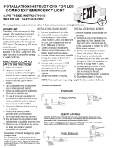
IMPORTANT SAFEGUARDS
When using electrical equipment, basic safety precautions should always be followed, including the following:
READ AND FOLLOW ALL SAFETY INSTRUCTIONS
WARNING: FAILURE TO FOLLOW THESE INSTRUCTIONS AND WARNINGS MAY RESULT IN DEATH, SERIOUS
INJURY OR SIGNIFICANT PROPERTY DAMAGE – For your protection, read and follow these warnings and instructions
carefully before installing or maintaining this equipment. These instructions do not attempt to cover all installation and
maintenance situations. If you do not understand these instructions or additional information is required, contact Holophane or
your local Holophane distributor.
WARNING: RISK OF ELECTRIC SHOCK - NEVER CONNECT TO, DISCONNECT FROM OR SERVICE WHILE
EQUIPMENT IS ENERGIZED.
WARNING: DO NOT USE ABRASIVE MATERIALS OR SOLVENTS. USE OF THESE SUBSTANCES MAY DAMAGE
FIXTURE, WHICH MAY RESULT IN PERSONAL INJURY.
WARNING: RISK OF PERSONAL INJURY - This product may have sharp edges. Wear gloves to prevent cuts or abrasions

when removing from carton, handling, installing and maintaining this product.
WARNING: The battery used in this device may present a risk of fire or chemical burn if mistreated. Temperature range 32
° F -122 ° F (0°C – 50°C) with Non-CW unit and -22 ° F -122 ° F (-30°C – 50°C) for CW units. Do not disassemble or heat above
70° C (158° F) or incinerate. Battery should not be used in an application where the temperature is lower than what is rated on
the spec sheet. Replace battery only as directed on the battery label and page 4 of these instructions. Use of unauthorized
battery voids warranty and UL listing of this product and may present a risk of fire or explosion.
Disconnect A.C. power before servicing.
All servicing should be performed by qualified personnel.
Consult your local building code for approved wiring and installation.
For use Outdoors. Failure to ensure conduit connections are properly protected against water ingress during installation
may void warranty.
Do not mount near gas or electric heater.
Equipment should be mounted in locations and at heights where it will not readily be subjected to tampering by
unauthorized personnel.
The use of accessory equipment not recommended by the manufacturer may cause an unsafe condition.
Do not use this equipment for other than intended use.
SAVE THESE INSTRUCTIONS AND DELIVER TO OWNER AFTER INSTALLATION
INSTALLATION and MOUNTING
IMPORTANT: Provide each unit with a single-phase AC un-switched power supply from a 120 V to 347 V circuit used for normal
lighting. PRODUCT DAMAGE WILL OCCUR IF THE RATED INPUT VOLTAGE IS EXCEEDED.
WARNING: During installation of remotes, input wires from main unit to remote units must NOT be connected to each other or
connected to ground. Failure to due so will lead to failure of the main unit.
NOTE: The battery must be connected to the charger board prior to applying AC power to the unit. Battery damage may occur if
the battery is connected longer than 24 hours without continuous AC power provided. See also “Important Battery
Information“,
NOTE: The maximum mounting height of DSL3 SP640L is 31.9 feet, the DSL3 SP1100L is 47.2 feet and the DSL3 SP2200L is
64.5 feet respectively, to meet the minimum illumination requirements of NFPA 101 (current Life Safety Code).
NOTE: Before installation, choose a location that allows adequate clearance for sliding the Rear Housing onto the Mounting
Bracket (minimum 6-1/2″ above top edge of Bracket)
NOTE: Do not connect battery or power unit until remote units (if applicable) are fully connected and wires are isolated from
other potentials (i.e. remote wires shall be isolated from earth ground).
MOUNTING BRACKET
1
Universal Mounting Bracket
1. Rear housing snap lock feature works in this hole
2. Unistrut® Mounting Holes (4)
3. Pole Mount Banding Slots (8)
4. Mounting Bayonets (4)

5. Wall/Ceiling Mounting Holes (4)
2
a. Wall/Ceiling mounting- Locate mounting bracket in desired location using “Wall/Ceiling Mounting Holes” (see Fig. 1). Install
using four (4) 30 lbs. min. Pullout rated fasteners. Mounting surface should be suitable to support 120 lbs.
b. Pole/Column Mounting-
1. Unistrut Mounting holes for most standard configurations.
2. Steel Banding Slots for routing around poles and I-beams. (See “Pole Mount Banding slots “above).
After the Mounting Bracket is in place and the conduit is near, slide the enclosure downward onto the Mounting Bayonets (See
Figure 2). The enclosure will be in place when the snap-lock feature is engaged in the hole in the Mounting Bracket.
SURFACE CONDUIT MOUNTING
1
At the top left or either side of the housing, drill a hole sized for the chosen conduit fitting. Conduit entry points can accommodate
a hole up to 1″ diameter and have a wall thickness up to .25″. Secure mounting plate to wall surface using fasteners with a
minimum pullout rating of 30 lbs. each.
IMPORTANT: prior to drilling out a hole on the top conduit location, remove the charger board assembly to ensure no damage
occurs to the charger board.
1. Three drill location provided for conduit entry.(One is opposite side)
2
Remove any debris from the enclosure, as it may harm electronic components or compromise the enclosure seal. Install a UL-
listed, water-tight fitting which is suitable to the size of the incoming conduit and hole drilled in step 1. The fitting must prevent
water ingress at the sealing joint with the enclosure, as well as from moisture which may be inside the conduit itself. Make code-
approved wire connections to the AC power supply and remote lamps (if applicable). See Wiring Diagram.

IMPORTANT: Follow any manufacture recommendations when attaching conduit to the conduit fitting. Failure to do so can lead
to moisture buildup in the conduit which may leak into the housing and damage the unit.
FLEXIBLE CONDUIT ONLY
TESTING and MAINTENANCE
NOTE: Emergency lighting systems should be tested in accordance with NFPA 101 or as often as local codes require,
to ascertain that all components are operational. NOTE: Allow batteries to charge for 24 hours before initial testing.
Manual testing:
If the batteries are sufficiently charged, either press and release the “TEST” button or use the RTKITHLP (remote tester
accessory for SDRT units only) on the bottom of the unit to activate a 60-second test, during which the lamps will turn on.
Triggering either option a second time will enable a 90-minute tests indicated by 5 flashes of the lamps. Triggering either option a
third time will disable manual testing.
Self-Diagnostics (SDRT feature)
Units with this option automatically perform a 5-minute self diagnostic test of the charging electronics, battery, and lamps every
30 days, and a 90-minute test every year, indicating system status as shown in the table at right. First self test occurs after 15
days of continuous AC Power.
Postponing a self-test:
If an automatic self-test occurs at a time when it is not desirable for the unit lamps to be on, it can be postponed for 8 hours either
by pressing and releasing the “TEST” button or by using RTKITHLP (remote tester accessory).
Cancelling emergency operation:
While in emergency Mode, press and hold the “TEST” button for several seconds or activate using the RTKITHLP (remote tester
accessory), during which the status indicator will flash until the lamps turn off. This restores the AC Reset state in which the unit
is shipped.
Load-Learning feature:
Self-Diagnostic units automatically `learn’ their total connected lamp load during the first scheduled self-test (~15 days). The

load-learn clear process can be initiated manually and should be initiated whenever the total connected lamp load of the unit is
changed, or potentially troubleshooting a lamp error (unit indicates a lamp error yet all lamps are operating correctly) or a lamp is
replaced.
To clear the current load-learn, press and hold the “TEST” button for 7 seconds (count green flashes), during this period the
lamps will turn on. After 7 seconds, release the button, the lamps will turn off within 2 seconds indicating load clear is complete. If
lamps stay on longer, the load clear was not successful and the process should be repeated. A new load learn will automatically
take place at the next discharge from a fully charged state (solid green status indicator).
Clearing a failure indication:
After a failure condition has been corrected and power is restored to the unit, clear the failure indication either by pressing the
“TEST” button once or by using the RTKITHLP (remote tester accessory).
IMPORTANT BATTERY INFORMATION:
Batteries are perishable items. For best results, it is recommended that the batteries receive an initial charge within the first
twelve months of the manufacture date of the fixture. In many cases, batteries beyond the initial charge recommendation time
frame will recover if fully charged soon after installation. If such a battery does not recover after a full initial charge, it should be
replaced. The manufacture date can be found on the outside of the unit packaging and on the product label as part of the Date
Code / Series. The first two digits in the date code represent the year and the second two digits represent the month.
Unit Status Indications
The “TEST” button illuminates to indicate the following conditions:
Indication: Status:
Off Unit is off
Flashing green Unit is in Emergency operation or Test
Solid amber Battery is charging
Solid green Battery is fully charged
Flashing R / G Manual test, battery not fully charged (SDRT)
1x red flashing Battery failure (SDRT)
2x red flashing Lamp failure (SDRT)
3x red flashing Charger / electronics failure (SDRT)
Flashing R/Amber Unable to charge
Solid Red Battery is disconnected
Remote Test (SDRT): (RTKITHLP sold separately)
Units with the self-diagnostics/remote test feature allows manual test activation using a laser pointer. Aim the laser beam straight
onto the circular area labeled near the “TEST” button for a few moments to activate a 60-second test. (See also “Manual testing”)
A test in progress may be cancelled by aiming the beam at the test area again. NOTE: The remote tester should not be used to
initiate the Load Learning feature.

1. Remote Test: aim laser pointer here
2. “TEST” button
MAINTENANCE
TO OPEN THE UNIT:
1 Unscrew the two nylon screws on the top of product with a screw driver.
1. Nylon Screw
Torque = 10 in-lbs
2 Open the unit and service the unit if necessary. When closing, ensure that wires are not pinched and proceed to screw two
nylon screws back into position.

BATTERY REPLACEMENT:
1 Disconnect battery from charger board. Release battery strap.
Std LiFePO4 Battery
2 Replace battery, secure the strap snugly, and reconnect to the charger board.
HO LiFePO4 Battery
3 Re-assemble the unit
EHO LiFePO4 Battery

1. Battery Strap
BATTERY HANDLING WARNINGS:
Dispose of used batteries promptly.
Keep away from children.
Do not disassemble.
Do not dispose of in fire.
LAMP REPLACEMENT
1 With unit open, disconnect the lamphead harness from the charger board. Refer to wiring diagram from page 6 for lamphead
connectors on charger board.
2 Remove the nut and washer from the lamphead and carefully remove the lamphead from the housing.
3 To reinstall lamphead, route harness through housing, washer and nut and then tighten nut down a ¼ turn after the gasket
begins to compress. Connect lamphead harness to charger board (see page 6 for wiring diagram).
1. Hex Nut
2. Nylon Washer
CHARGER BOARD REPLACEMENT
1 Lift charger board tray and open dielectric cover. Disconnect all harnesses connected to the charger board.

1. Dielectric Cover
2 To remove the charger board from tray release snaps (5x) and remove. To install new charger board place over snaps in
correct orientation with dielectric cover installed under the charger board as shown. Press down firmly until snaps engage.
1. Snaps
2. Charger board
3. Tray
3 Reconnect all harness and position the end of the charger board tray onto guide rails and push down until you hear a “snap”.
Route wires along the side of the guide rail to avoid wires from pinching. Battery harness must be routed through flap in dielectric
cover.
1. Battery harness routing location
LAMP AIMING and WIRING DIAGRAM

LAMP AIMING
1 With unit open, loosen the nut and screw and aim the lamp head to the desired position.
2 With lamp heads aimed, begin by tightening the nut until the gasket is fully compressed.
(Torque spec: 12 in-lbs)
3 With nut secure, tighten the screw to finish aiming procedure.
(Torque spec: 10 in-lbs)
1. Hex Nut
2. Nylon Washer
3. Gasket
4. Screw
WIRING DIAGRAM
1. DC output to the remote units.
Yellow/Red stripe (+)
Blue/Black stripe (-)
2. Battery Connector
3. Lamp head Connector
4. Status LED Connector
5. Heater Connector (CW Option Only)
6. AC input Connector
White: Neutral
Black: HOT 120-347Vac, 50/60Hz
Federal Communications Commission (FCC) Requirements:

This device complies with FCC Title 47, Part 15, Subpart B.
This device does not cause harmful interference.
LIFE SAFETY SOLUTIONS
TEL: 740-345-9631
www.Holophane.com
Part # 912-00031-002
Rev. K, 11/2021
© 2020, Acuity Brands Lighting, Inc.
All Rights Reserved.
Documents / Resources
AcuityBrands DSL3 Emergency Lighting Unit [pdf] Instruction Manual
DSL3 Emergency Lighting Unit, DSL3, Emergency Lighting Unit, Lighting Unit, Unit
AcuityBrands DSL3 Emergency Lighting Unit [pdf] Instruction Manual
DSL3 Emergency Lighting Unit, DSL3, Emergency Lighting Unit, Lighting Unit
References
Acuity Brands | Lighting, Controls, and Building Management Solutions
U.S. Environmental Protection Agency | US EPA
Holophane | Lighting solutions for commercial, industrial, emergency and outdoor applications.
Lithonia Lighting® | Best Value in Lighting
Manuals+,
home
privacy
/