01
SEC1000S of GoodWe Technologies Co., Ltd. (hereinafter referred to as GoodWe) has been designed
and tested strictly according to the international safety regulation.As electrical and electric
equipment,Safety Regulation shall be followed during installation and maintenance.Improper
operation may bring severe damage to the operator,the third party and other properties.
• Installation.maintenance of SEC1000S must be performed by qualied personnel.in compliance
with local electrical standards. regulations and the requirements of local power authorities.
• To avoid electric shock,make sure the connection between SEC1000S and AC output of inverter.
SEC1000S and Grid, is disconnected before performing any installation or maintenance.
• When in operation,users should not touch any of the electrical parts of SEC1000S ,like internal
components.cables, to avoid electic shock.
• All electrical installations must comply with local electrical standards and obtain permission from
local power authorities before SEC1000S can be connected to the grid by professionals.
• Before replacing any internal components of SEC1000S, the connection between the inverter
and SEC1000S,the power grid and SEC1000S must be disconnected, and the newly replaced
components must meet the requirements of SEC1000S. Otherwise, GoodWe will not assume the
responsibility and quality assurance for the personal harm.
• Make sure that the AC input voltage and input current match the rated voltage and current of
SEC1000S, otherwise the components will be damaged or cannot work properly,and GoodWe will
not assume the responsibility and quality assurance for this case.
• There are lightning protection modules inside.Make sure to connect the internal PE with the
ground when intalling SEC1000S.
• When in operation, do not plug or unplug cables of SEC1000S.
• SEC1000S must be Installed out of reach of children.
• Appropriate antistatic measures should be taken.
• SEC1000S supports the three-phase four-wire grid structure only.
• Can only be used in spontaneous self-use mode.
2 Safety and Warning
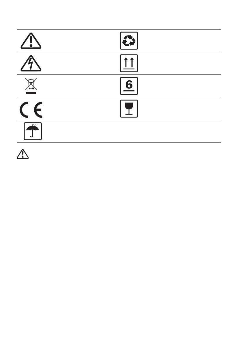
1 Symbols
Keep Dry – The package/product must be protected
from excessive humidity and must accordingly be
stored under cover.
Caution! - Failure to observe a warning
indicated in this manual may result in
minor or moderate injury.
This side up - The package must always be
transported, handled and stored in such a way
that the arrows always point upwards.
The package/product should be
handled carefully and never be
tipped over or slung.
Components of the product can be
recycled.
Danger of high voltage and electric
shock!
Product should not be disposed as
normal house hold waste.
No more than six (6) identical
packages be stacked on each other.
CE Mark