Goodwe XS Series Grid-Tied PV Inverter User manual

Type
User manual
GoodWe Technologies Co., Ltd.
No. 90 Zijin Rd., New District, Suzhou, 215011, China
www.goodwe.com
service@goodwe.com V2.9-2022-09-20
XS Series
0.7-3.3kW
User Manual
Grid-Tied PV Inverter
1 Symbols .............................................................................................................................. 01
2 Safety Measures & Warning ....................................................................... 02
3 Product Introduction ........................................................................................ 04
3.1 Inverter Overview ...................................................................................................................... 04
3.2 Package ....................................................................................................................................... 05
4 Installation ..................................................................................................................... 06
4.1 Mounting Instructions ............................................................................................................... 06
4.2 Equipment Installation ............................................................................................................. 06
4.3 Electrical Connection ................................................................................................................ 08
4.4 Communication Connection ................................................................................................... 12
5 System Operation .................................................................................................. 18
5.1 LCD Panel .................................................................................................................................... 18
5.2 User Interface And System Configuration .............................................................................. 18
5.3 Error Message .............................................................................................................................. 25
5.4 Wi-Fi Reset & Wi-Fi Reload ........................................................................................................ 25
5.5 Precaution For Initial Startup .................................................................................................. 26
5.6 Special Adjustable Setpoints ................................................................................................... 26
6 Troubleshooting ...................................................................................................... 29
7 Maintenace .................................................................................................................... 31
8 Technical Parameters ..................................................................................... 32
9 Power off the inverter ..................................................................................... 42
01 02
2 Safety Measures & Warning
The XS-Series strictly conforms and has been tested according to international safety regulations.
GOODWE strongly advises installers to follow the local safety regulations during the commission-
ing, operation and maintenance of the XS-Series inverter. An improper operation may result in
electric shocks or damage to equipment and property.
The installation, maintenance and connection of the inverters must be performed by qualified
personnel, in compliance with local electrical standards, regulations and following the regula-
tions of the local power suppliers, companies and related authorities.
• To avoid electric shocks, the DC input and AC output port of the inverters must be disconnected
and wait at least 5 minutes before performing any installation or maintenance.
The temperature of some components of the inverters may exceed 60℃ during operation. To
avoid being burnt, do not touch the inverter during operation. Let it cool before touching it.
• Keep children away from the inverter.
Touching or changing inverter components without following the GOODWE's manual instruc-
tions may cause personal injury, damage the inverters and ultimately be a reason for warranty
invalidation.
The electronic components of the inverter may be damaged by static electricity. Appropriate
methods must be adopted to prevent such damage, otherwise the GOODWE's warranty may be
void.
Make sure that the output voltage of the proposed PV array is lower than the maximum rated
input voltage of the inverter; otherwise the inverter may be damaged and the warranty may be
void.
• When exposed to sunlight, the PV array generate dangerous high DC voltage; we strongly opera-
tors to strictly follow the GOODWE's instructions and avoid actions that put lives at risk.
The PV modules should have as a minimum an IEC61730 class A rating protection.
• If the equipment is used in a way not authorized by the GOODWE, the equipment built-in protec-
tions may be damaged.
• In order to achieve a complete isolation of the equipment: Turn off the DC switch, disconnect the
DC terminal, the AC terminal and the AC breaker
• Do not insert or pull the AC or DC terminals when the inverter is in operation.
• An earthing photovoltaic system requires the installation of an Arc Fault Detector on the DC side.
The below bullet points are not understandable. Urgently review!
• The inverter can exclude the possibility of DC residual currents to 6mA in the system,
• Where an external RCD is required in addition to the built-in RCMU, type A RCD must be used to
avoid tripping.
Failure to observe a warning indicated in this manual may result in
injury.
Recyclable materials
Danger of high voltage & electric shock
This side up - The package must always have the
arrows point up
Special disposal instructions
Refer to operation instructions
CE mark.
1 Symbols
Don't touch, hot surface!
No more than eight (8) identical packages
be stacked on each other.
Fragile
Wait at least 5 minutes after disconnecting the inverter before
touching internal parts
Keep Dry
8
5min
• The PV is not grounded as default configuration.
• Inverters should not be used in multiple inverter combinations.
• The inverters are not suitable for power limitation for multiple inverters.
To ensure that the IP65 protection is maintained, please make sure that the inverter is
rigorously packed and its component sealed properly. The GOODWE strongly suggests to
install the inverter at most one day after it has been unpacked. If this is not the case and
the installation takes longer, please re-seal all the unused terminals and ensure that the
inverter and its components are not exposed to water or dust.
To our inverter product, GOODWE provides standard manufacture warranty which comes with the
product and prepaid warranty extension solution to our customer. You can find the details about
the terms and solution from below linkage.
https://en.goodwe.com/warranty.asp
03 04
The XS-Series strictly conforms and has been tested according to international safety regulations.
GOODWE strongly advises installers to follow the local safety regulations during the commission-
ing, operation and maintenance of the XS-Series inverter. An improper operation may result in
electric shocks or damage to equipment and property.
The installation, maintenance and connection of the inverters must be performed by qualified
personnel, in compliance with local electrical standards, regulations and following the regula-
tions of the local power suppliers, companies and related authorities.
• To avoid electric shocks, the DC input and AC output port of the inverters must be disconnected
and wait at least 5 minutes before performing any installation or maintenance.
The temperature of some components of the inverters may exceed 60℃ during operation. To
avoid being burnt, do not touch the inverter during operation. Let it cool before touching it.
• Keep children away from the inverter.
Touching or changing inverter components without following the GOODWE's manual instruc-
tions may cause personal injury, damage the inverters and ultimately be a reason for warranty
invalidation.
The electronic components of the inverter may be damaged by static electricity. Appropriate
methods must be adopted to prevent such damage, otherwise the GOODWE's warranty may be
void.
Make sure that the output voltage of the proposed PV array is lower than the maximum rated
input voltage of the inverter; otherwise the inverter may be damaged and the warranty may be
void.
• When exposed to sunlight, the PV array generate dangerous high DC voltage; we strongly opera-
tors to strictly follow the GOODWE's instructions and avoid actions that put lives at risk.
The PV modules should have as a minimum an IEC61730 class A rating protection.
• If the equipment is used in a way not authorized by the GOODWE, the equipment built-in protec-
tions may be damaged.
• In order to achieve a complete isolation of the equipment: Turn off the DC switch, disconnect the
DC terminal, the AC terminal and the AC breaker
• Do not insert or pull the AC or DC terminals when the inverter is in operation.
• An earthing photovoltaic system requires the installation of an Arc Fault Detector on the DC side.
The below bullet points are not understandable. Urgently review!
• The inverter can exclude the possibility of DC residual currents to 6mA in the system,
• Where an external RCD is required in addition to the built-in RCMU, type A RCD must be used to
avoid tripping.
3 Product Introduction
3.1 Inverter Overview
XS series inverter illustration.
1. DC Switch (Optional)
2. PV Input Terminals
3. WiFi/LAN Module Port
(Optional)
4. CT & DRED/Remote Shutdown
/RS485 Port (Optional)
5. AC Output Terminal
6. LCD
7. Indicator Light
8. Button
• The PV is not grounded as default configuration.
• Inverters should not be used in multiple inverter combinations.
• The inverters are not suitable for power limitation for multiple inverters.
To ensure that the IP65 protection is maintained, please make sure that the inverter is
rigorously packed and its component sealed properly. The GOODWE strongly suggests to
install the inverter at most one day after it has been unpacked. If this is not the case and
the installation takes longer, please re-seal all the unused terminals and ensure that the
inverter and its components are not exposed to water or dust.
To our inverter product, GOODWE provides standard manufacture warranty which comes with the
product and prepaid warranty extension solution to our customer. You can find the details about
the terms and solution from below linkage.
https://en.goodwe.com/warranty.asp
Item
1
2
3
4
5
6
7
8
Name
DC Switch
PV Input Terminal
WiFi/LAN Module Port
(Optional)
CT & DRED/Remote
Shutdown/RS485
Communication Port
AC Output Terminal
LCD
Indicator Light
Button
Description
For PV string connection
For WiFi/LAN communication
For CT and DRED & Remote Shutdown & RS485 Communication
For AC cable connection
Inverter operation data viewing and parameter configuration.
Display the state of the inverter
For configuration and viewing parameters.
1 2 3 4 5
2 3 4 5 68
7
With DC Switch
Without DC Switch
During normal operation it is in "on" state, it can shut down
the inverter after it is disconnected from the grid by the AC breaker.
For Australia and New Zealand: With DC Switch .
05 06
To allow for a dissipation of the heat and in order to facilitate dismantling, the space around the
inverter should allow for some clear spaces.
The spacing around inverter should met the requirements as illustrated in below figures for the
sake of heat dissipation and demounting.
Upward
Downward
Front
Both sides
-------------- 300mm
---------- 500mm
----------------- 300mm
---------- 200mm
200mm 300mm200mm
300mm
500mm
4.2 Equipment Installation
4.2.1 Select installation location
Please take the following points into consideration when you are selecting a proper location to
install inverter.
• Please choose appropriate mounting methods and installation location in terms of weight and
dimension of inverter.
• The location must be well ventilated and sheltered from direct sunlight.
• Install inverter vertically or with a backward tilt within 15 degrees. No lateral tilt is allowed. The
inverter should not be tilted sideways. The area of the connectors should point downwards.
4 Installation
4.1 Mounting Instructions
1. In order to achieve optimal performance, the ambient temperature should be lower than 45℃.
2. For easy maintenance, we suggest to install the inverter at eye level.
3.Mounting Support Requirements:
• The mounting support shall be nonflammable and fireproof.
• Make sure that the support surface is solid enough to bear the product weight load.
• Do not install the product on the support with poor sound insulation to avoid the noise
generated by the working product, which may annoy the residents nearby.
4. Product label and warning symbols should be placed at a location that is easy to read by the
users.
5. Make sure to install the inverter at a place where it is protected from direct sunlight, rain and
snow.
Accmulated snow
Keep away
from sunlight Keep dry Keep it clear
of snow Sun Rain
Max
15°
3.2 Package
The unit is thoroughly tested and strictly inspected before delivery. Damage may still occur
during shipping.
1. Check the package for any visible damage upon receiving.
2. Check the inner contents for damage after unpacking.
3. Check the package list below.
Positive DC Plug Negative DC PlugInverter
or
AC Terminal Grounding Screw
Text Information
Allen Wrench
(VACONN AC Plug Only) PE TerminalTerminal[1]
Expansion Bolts
Communication
Module
Wall-mounted
Bracket
[1] The terminal is used for CT/Remote Shutdown/RS485 function.
Bluetooth Module
(optional)
07 08
4.2.2 Mounting procedure
1. Use the wall-mount bracket as a template and drill holes with 10mm in diameter and 80 mm in
depth on the wall.
2. Fix the wall-mount bracket on the wall with the expansion bolts in the accessories bag.
3. Hold the inverter by the side groove.
4. Mount the inverter onto the wall-mount bracket.
170mm
85mm
20mm
Mounting Bracket Expansion Pipe
Self-tapping Screws
4.3 Electrical Connection
4.3.1 Connection To The Grid (AC Side Connection)
1. When connecting the inverter make sure to adjust the voltage and the frequency in compliance
with the grid regulations and the specifications of the GOODWE.
2. Add a breaker or fuse to the AC side. Please note that the specification should be more than 1.25
times of rated AC output current.
3. The PE line of the inverter should be connected to earth. Make sure the impedance of neutral
wire and earth wire is less than 10ohm.
4. Disconnect the breaker or fuse between the inverter and the utility.
5. Please note that there are two AC connector brands compatible with the inverters: VACONN and
Exceedconn. Choose one of the to connect the inverter to the grid.
6. When laying the AC line make sure that the protective earthing conductor is not strained.
VACONN AC connectors installation instruction
Inverter are compatible with two brands of AC connector: VACONN and Exceedconn
Where an external RCD (Residual Current Device) is required in addition to the built-in RCMU
(Residual Current Monitoring Unit), and a type A RCD must be used to avoid tripping.
VACONN Series Exceedconn
Exceedconn connectors installation instruction
Tighten screw clockwise
8-10mm
Inverter
Material (Annealed copper wire)
Tighten three screws and ensure no
screw head exceeds the surface
7-9mm
Torque 0.7~0.9N.m
unlock
lock
When unplugging the AC terminals, press the
button and hold it to unlock
Make sure the terminal is rotated to the lock position before the inverter is started
Inverter model Recommended RCD specifications
GW700-XS
GW1000-XS
GW1500-XS
GW2000-XS
GW2500-XS
GW3000-XS
GW2500N-XS
GW3000N-XS
GW700-XS-11
GW1000-XS-11
GW1500-XS-11
GW2000-XS-11
GW2500-XS-11
GW3000-XS-11
GW3000-XS-B11
300mA
300mA
300mA
300mA
300mA
300mA
300mA
300mA
300mA
300mA
300mA
300mA
300mA
300mA
300mA
09 10
* Neutral wire is blue, live wire is brown (preferred) or black and protective earth wire is yellow-green.
* Rotate (tightening torque: 0.6N.m) the connector of AC cable into the corresponding terminal.
4.3.2 AC circuit breaker and leakage current protection device
Please install an independent two pole circuit breaker to protect the inverter and make sure it is
safe to disconnect it from the grid.
In addition to the built-in RCMU, an external RCD is required to ensure that the inverter system
does not carry DC residual currents. To avoid tripping, the types A can be used.
Annealed copper wire
Grade
A
B
C
Description
O.D.
Conductor Material Sectional Area
Bare Wire Length
Value
10~12mm
2.5~4mm2
10mm around
A B C
AC cable specification
Note: it is not recommended that multiple inverters share a single circuit breaker.
The integrated leakage current detection device of the inverter can detect external leakage
current in real time. When the detected leakage current exceeds the limit value, inverter will
quickly disconnect with the grid, if the leakage current protection device is installed externally, the
tripping current should be 300mA or higher.
4.3.3 DC Side Connection
1. Before connecting the PV strings, please ensure the plug connectors have the correct polarity.
Incorrect polarity has the potential to cause permanent damage to the unit.
2. The open circuit voltage of the PV strings cannot exceed the maximum input voltage of the
inverter.
3. Only the GOODWE supplied DC connectors are suitable for use.
4. The positive and negative pole should not be connected to the PE wire (ground wire). Not
following this instruction may cause damage to the inverter.
5. Do not connect the positive or negative poles of the PV string to the PE wire. Not following this
instruction may cause damage to the inverter.
6. Red represents positive, black represents negative.
Inverter Model
GW700-XS/GW1000-XS/GW1500-XS/
GW700-XS-11/GW1000-XS-11/GW1500-XS-11
GW2000-XS/GW2500-XS/GW3000-XS/
GW2500N-XS/GW3000N-XS/GW3300-XS/
GW3KB-XS/GW2000-XS-11/GW2500-XS-11/
GW3000-XS-11/GW3000-XS-B11
Recommended Circuit Breaker Specifications
16A
25A Please use solar PV cable in DC connection.
(4mm PV1-F wire recommended)
7. For the XS series the minimum insulation resistance to the ground of the PV panels must
exceed 16.7kΩ (R=500/30mA). There is risk of shock hazard if this minimum resistance
requirement is not me.
There are four types of DC connectors, DEVALAN, MC4, AMPHENDL H4 and QC4.10 series.
DEVALAN SERIES MC4 SERIES
AMPHENOL SERIES QC4.10 SERIES
Note: The actual DC connector used is as shown in the accessory box.
DC cable specification:
Value
4~5mm
2.5~4mm2
About 7mm
Label
A
B
C
Description
External diameter of wire stock
Cross-sectional area of conductor material
Length of bare wire
A B
C
Please use special tools to do crimping
MC4 & QC4.10 DEVALAN & AMPHENOL
Do not crimp wire
into the limit buckle.
Negative connector
Positive connector
Inverter side
The installation method of DC connector.
11 12
4.4.1 Wi-Fi Communication
Wi-Fi communication option is only applicable to Wi-Fi version inverter and Wi-Fi communication
module is required. Please refer to "Wi-Fi Configuration Instruction" in the accessory box for
detailed instruction.
The WiFi module installation of XS series are shown as below.
This port is used for connection of Wi-Fi or LAN module only. No connection to USB is
allowed. Do not connect PC or other devices to this port.
4.3.4 Earth Terminal Connection
The inverter is equipped with earth terminal according to the requirement of EN 50178.
All non-current carrying exposed metal parts of the equipment and other enclosures in the PV
power system must be grounded.
Please follow the steps below to connect "PE" cable to ground.
A
B
C
NO.
A
B
C
Name
Cold-pressed terminal
Screw
Green & Yellow Cable
Explanation
M5*14 (1~1.5Nm)
4mm2 / 10AWG
L1
L2 = L1 + (1~2mm)
Step 1
Strip the wire insulation sheet of a suitable length with a wire stripper.
Step 2
Insert the stripped wire into the terminal and compress it tightly by crimping pliers.
Step 3
Fix the earth wire on the machine.
In order to improve the corrosion resistance of the terminal, it is recommended to apply
silica gel on the earth terminal for corrosion protection after the grounding cable
assembly is completed.
4.4 Communication Connection
After the installation, confirm whether the indicator on the module is on.
If the indicator is off, the module needs to be unplugged and installed again.
Unlocking tool
4.4.2 LAN Communication
LAN Communication is only application to LAN version inverter and LAN Communication module
is required.
13 14
Step 4:
Connect the terminal to the right position onto the inverter.
NO.
3
7
6
8
Function
RS485-
RS485+
13
68
5 4
2
7
13
68
5 4
2
7
Step 3:
Put the cable through the connector and connect to the terminal.
For single inverter connection
Please connect RS485 cables to 'RS485-' port (3 or 7) and 'RS485+'
port (6 or 8).
NO.
3
7
6
8
Function
RS485-
RS485+
For multiple inverter connection
Please connect RS485 cables to 'RS485-' port (3 or 7) and 'RS485+'
port (6 or 8).
Note: When in multi-machine parallel, please ensure that terminals
at both ends of the 2-pin cable are connected with the same polarity.
RS485-RS485+
13
68
5 4
2
7
13
68
5 4
2
7
RS485-RS485+
4.4.3 RS485 Communication
RS 485 communication option is only applicable to RS485 version inverter and RS485 communi-
cation function is required.
RS485 communication connection of XS series are shown as below.
Step 1
Dismount the terminal in the accessory box.
Step 2:
Dismantle the resistor or shortcircuit cable.
15 16
NO.
1
2
Function
CT -
CT +
Table 1
Power Limiting
NO.
3
4
5
6
7
8
Function
DRM1/5
DRM2/6
DRM3/7
DRM4/8
REFGEN
COM/DRM0
Table 2
DRED
13
68
5 4
2
7
6.5mm
25mm
6.5mm
25mm
NO.
4
5
Function
Content +
Content -
Table 1
Remote Shutdown
13
68
5 4
2
7
6.5mm
25mm
Step 2:
Put the cable through the plate.
Different cable and connection method should be applied for different functions. Please
follow the connection steps in accordance to the function in need.
CT and DRED
Please connect the cables in order as shown
in the right table.
Remote Shutdown
Please connect the cables in order as shown in the right table.
CT and Remote Shutdown
Please connect the cables in order as shown in the right table.
NO.
1
2
Function
CT -
CT +
Table 1
CT
NO.
4
5
Function
Content +
Content -
Table 2
Remote Shutdown
13
68
5 4
2
7
6.5mm
25mm
4.4.5 DRED / Remote Shutdown / CT(Power Limit Device) Connection
DRED (Demand response enabling device) is only for Australian and New Zealand installations, in
compliance with Australian and New Zealand safety requirements.
Contat the after-sales service to get the DRED terminal if you need to use DRED function.
DRED function is off by default. Start this function via SolarGo App if it's needed.
Remote shutdown is only for Europe installations, in compliance with European safety require-
ments. And Remote shutdown device is not provided by GOODWE.
Remote shutdown function is off by default. Start this function via SolarGo App if it's needed.
Detailed operation is shown as below:
Step 1
Dismantle the resistor or shortcircuit cable.
4.4.4 Export Power Limit Connection Diagram
The methods of connecting the Power Limiting device CT is shown below.
CT90-5 or CT90-30 is recommended.
white Wire
Inverter Switch Board
LN
Router
Black
Wire
CT+
CT-
Note: Correct direction of CT: House (K)→Grid(L).
Incorrect connection or direction will cause incorrect data.
K
L
17 18
5 System Operation
Indicator lights in Yellow/Green/Red correspondently refer to:
Button
Explanation
ON = WiFi connected/active
BLINK 1 = WiFi system resetting
BLINK 2 = Not connect to router
BLINK 3 = WiFi server problem
BLINK = RS485 connected
OFF = WiFi not active
On = Inverter is feeding power
OFF = Inverter is not feeding power at the moment
On = Fault occurred
OFF = No fault
StatusIndicator
Power
Run
Fault
SEMS Portal App
Note:
1. Compatible DRED commands are DRM0, DRM5, DRM6, DRM7, DRM8.
2. Please set up power limit function at local setting page once all connection steps are done.
3. CT is directional. Please make sure CT+ is properly connected to white & black wire and CT- to
black wire. Please make sure the limit buckle is connected to the output live wire (L) of
inverter.
4. If CT is not well connected, it will display "CT disconnected" on the inverter. If CT is reversely
connected, it will display "CT Reverse" on the inverter when connected to grid.
4.4.6 Earth Fault Alarm
In compliance with the section 13.9 of IEC62109-2, the XS series inverter is equipped with an earth
fault alarm. When earth fault occurs, the fault indicator at the front LED screen will light up. On
inverters with Wi-Fi communication, the system sends an email with the fault notification to the
customer. For inverters without Wi-Fi, the buzzer of the inverter will keep ringing for one minute
and ring again after half an hour until the fault is resolved. (This function is only available in Austra-
lia and New Zealand).
4.4.7 SEMS Portal
SEMS Portal is an online monitoring system. After completing the installation of
communication connection, you can access www.semsportal.com or download
the App by scanning the QR code
to monitor your PV plant and device.
Please contact the after-sales for more operation of SEMS Protal.
Step 3:
Connect the terminal to the right position onto the inverter.
5.2 LCD Panel
5.1 Power on the inverter
Step 1: Turn on the AC switch between the inverter and the utility grid.
Step 2: (optional) Turn on the DC switch between the inverter and the PV string.
Step 3: Turn on the DC switch of the inverter.
No. Check Item
1
2The PE, DC input, AC output, and communication cables are connected correctly and
securely.
The product is firmly installed at a clean place that is well-ventilated and easy to operate.
3Cable ties are intact, routed properly and evenly.
4Unused ports and terminals are sealed.
5The voltage and frequency at the connection point meet the inverter grid connection
requirements.
Check Items Before Switching Power on.
19 20
5.3 User Interface And Syetem Configuration
5.3.1 Operation Method
There are 2 modes of button operation: Short press the button and long press the button.
In all levels of menu, if no action is taken, the backlight of the LCD will switch off, the LCD will
automatically revert to the first item of the first level menu, and any modifications made to the
data will be stored into internal memory.
5.3.3 LCD
A schematic of the display screen is shown as below:
Display area is divided as follows:
5.3.4 Display Area
Line 1 --- Working status information
Line 2---Diaplays of the real-time power generated by the inverter.
This area displays the status information. "Waiting" indicates the inverter is standing by for
power generation; "Checking **S" (checking time is based on safety, and varies from country to
country) indicates is self-checking, counting down and preparing for power generation.
"Normal" indicates the inverter is generating power. If any condition of the system is abnormal,
the screen will display an error message.
Through button operation, the screen can display different information such as operation
parameters and power generation status is in this area. There are two levels of menus, and the
flow chart of first level menu is shown below:
5.3.5 Use Of The LCD
The display allows accessing the configuration of the basic parameters. All the language, time and
country settings can be configured by buttons. The menu, shown in the LCD displays area has two
Normal
Pac=XXXX.XW
Line ①
Line ②
Short press
and wait for 10s
wait for 10s
Long Press
Long Press
Long Press
Long Press
Long Press
Long Press
Long Press
Long Press
Long Press
Long Press
Long Press
Long Press Long Press Long Press
Short Press to select number 0 ~ 9
Initial Password: 1111
Short Press to select number 0 ~ 9 Short Press to select number 0 ~ 9
Short Press to select
number 0 ~ 9
Wait
Angielski
Short Press
Short Press
Short Press
Short Press
Short Press
Short Press
Short Press
Short Press
Short Press
Short Press
Short Press
Short Press
Short Press
Short Press
50Hz Grid Default
Lock
Ipv =xxx .xx A
Pac = xxx W
Fac =xx.xx Hz
Pac = xxx W
Error History
Pac = xxx W
Model
Pac = xxx W
Normal
Pac = xxx W
No Error UtilityLoss
190520 05:21
Vac=
xxx/xxx/xxx V
Iac=
xx.x/xx.x/xx.x
Vpv =xxx .xx V
Pac = xxx W
E-Total =xxx .xx KWh
Pac = xxx W
E-Today =xxx .xx KWh
Pac = xxx W
Password: 1111 Password: 1111 Password: 1111Password: 1111
New Zealand
Setting...
Set OK
Set Fail
Set OK
Set Fail
Setting�
English
Ver:V1.XX.XX
Pac=xxx W
Set Language
Pac=xxx W
Next page
5.3.6 Menu Introduction
When the PV panel is feeding power to the inverter, the LCD displays the first-level menu.
The initial display is the first item to the first level menu, and the interface displays the current
status of the system. It shows "Waiting" in the initial state; its display "Normal" during power
generation mode; if there is something wrong with the system, an error message is displayed.
Please refer to "5.3 Error message".
View PV voltage, PV current, grid voltage, current and frequency:
Short press the button to enter the "E-total" menu which displays the total power generation for
today.
Short press the button to enter the "E-total" menu which displays the total power generation
until today.
Short press the button to enter the "Vpv" menu which displays the PV voltage in "V".
5.3.2 Set Safety Country
After powering on for the first time, the inverter prompts Select Country/Region, please short
press until "GW1000-XS Pac=****.0W" is displayed, and then set the safety region. The inverter
cannot be connected to the grid before the safety-related area is set.
If display shows "GW1000-XS Pac=****.0W", then long press the button to enter the second level
menu. Short press to browse the countries available. Please wait after choosing the suitable
country's safety setting, the display will show "setting..." and skip to "Set OK" or "Set Fail".
NOTE: For the Australian market, to comply with AS/NZS 4777.2:2020, please select from Australia
Region A/B/C, please contact your local electricity grid operator on which Region to select. After
the safety area setting is completed, some parameters in the inverter system will take effect
according to the corresponding safety regulations, such as PU curve, QU curve, trip protection,
etc. If you need to change the configuration parameters, please refer to the SolarGo APP user
manual.
levels of menu. Short or long press the button will take you between menus and through each
menu. Items in the first level menu that have no second level are locked. For these items, when the
button is pressed for two seconds, the LCD will display the word "Lock" followed by data relating
to the first level menu item. The locked menu can only be unlocked under system mode switch-
ing, fault occurrence or button operation.
21 22
Short press the button to enter the "Ipc" menu which displays the PV current in "A".
Short Press the button to enter the "Vac" menu which displays the grid voltage in "V".
Short Press the button to once more to enter the "Iac" menu which display the grid current in "A".
Short Press the button to once more to enter the "Frequency" menu which displays the grid
frequency in "Hz".
View error code
Short press the button once more to enter the "Error Code history" menu.
Long press the button to enter the second level menu of error detection. The newest three invert-
er records will be shown by short pressing the button in this second level menu. The records
include error codes (EXX) and error times (110316 15:30).
View model name and reconfigure safety country:
From the error code history item in the first level menu, short press the button to see model
name. If you want to change the safety country, please long press the button, then LCD will enter
the second level menu. In the second level menu, short pressing the button can change the
safety country.
After choosing the suitable safety country, the inverter will store the chosen safety country if
there is no input for 20 seconds. If there is no exact proper country code, please choose "50Hz
Grid Default" or "60Hz Grid Default" accordingly.
View software version
From the model name item in the first level menu, short press the button to see the software
version. The current software version can be shown in this menu.
5.3.7 Basic Setting
Set language
Short press the button to enter the "Set Language" menu. Long press the button to enter the
second level menu. Short press the button to browse the languages available.
Set time
From the first level "Set Language" menu, short press the button to enter the "Set Time" menu.
Long press the button to enter the second level menu. The initial display is "2000-00-00 00:00", in
which the first four numbers represent the year (e.g. 2000~2099); the fifth and sixth numbers
represent the month (e.g. 01~12); the seventh and the eighth numbers represent the date (e.g.
01~31). The remaining numbers represent the time.
Short press the button to increase the number in current location, and press to move the cursor
to next position.
Set protocol:
The function is only used for service personnel, setting a wrong protocol could lead to
communication failure. From the first level "Set Time" menu, short press the button to enter
Long Press
Long Press
Long Press
Long Press
Long Press Long Press
Long Press
Long Press Long Press
Long Press
Long Press
Short press short press to
select"Leading" or "Lagging"
Short Press to select
number 8 or 9
Short Press to
select number 0 ~ 9
Short Press to
select number 0 ~ 9
Short Press to
select number 0 ~ 9
Short Press to select
number 0 ~ 9
Wait
Wait
Wait
Wait
Short Press
Short Press
Set Time
Pac = xxx W
Set OK
Set Fail
Setting�
2000-00-00 00:00 2000-00-00 00:00 ······ 2000-00-00 00:00
W/L Reset
Pac = xxx W
PF Adjust
Pac = xxx W
W/L Reload
Pac = xxx W
W/L Reloading
W/L Reload Fail
W/L Reload OK
W/L Resetting
W/L Reset Fail
W/L Reset OK
Disable Lagging 0.95Lagging 0.95Lagging 0.95
Set OK
Set Fail
Setting�
Long Press
Long Press
Long Press
Long Press Long Press
Long Press
Long Press
Long Press
Long Press
Previous page
Or
Set Calibrate Addr
Pac=xxx W
Long Press
Short Press
Short Press
Or Power Limit ON
Pac=xxx W
Power Limit OFF
Pac=xxx W
Set Power Limit
XXX%
Wait
Wait
Short press to select
number 0 ~ 2
Short press to select
number 0 ~1
Short press to select
number 0 ~9
Short press to select
number 0 ~9
Short press to select
number 0 ~9
Short press to select
number 0 ~9
Short Press Short Press
Shadow MPPT ON
Pac = xxx W
Shadow MPPT OFF
Pac = xxx W
Set Power Limit
XXX%
Set Power Limit
XXX%
Set Power Limit
XXX%
Set OK
Setting�
Set Fail
Set Addr: XXX Set Addr: XXX
Set Addr: XXX
Set OK
Set Fail
Setting�
23 24
"Set Protocol Display" menu. Long press the button to enter sub menu. The circulatory sub
menu including two protocols can be found. The protocol can be chosen by short pressing the
button.
• MPPT function for shadow:
The default setting for shadow optimizer is disabled.
Please enable shadow optimizer when there is shadow on PV panel. The function could help the
system generate more power under shadow condition. Please do not enable the function when
there's no shadows being casted onto the panel. Otherwise it could lead to lesser generated
power. Press the button until it enters the shadow optimize menu. When LCD displays "Shadow
MPPT OFF", it means the MPPT function for shadow is switched off. Long press the button to
enable the function. If LCD displays "Shadow MPPT ON" it means the shadow optimizer is on.
Long press the button to disable the function.
70% rated power limit
The function is only available for inverters in Germany. It can only be used by network operators.
Otherwise it will cause a loss of power generated from the PV plant.
Press the button till LCD displays the 70% rated power menu. If LCD displays 70% rated enable it
means the function to limit the inverter working under 70% of rated output is switched off. Long
press the button will switch this function on. If LCD displays recover rated power it means the
inverter is working under 70% of rated output power. Long press the button to recover inverter
to 100% of its rated output power.
5.3.8 Power Limiting Function Setting
Enter Password:
Please enter the password (valid for 10 minutes) before changing the power limiting state (the
default is OFF) and the power limiting setting (the default is 2% rated power): Long press the
button to enter password input menu. The initial display "1111" is the default password. Short
press the button to increase the number in current location and long press to move to the cursor
to next position. The operations are shown as below.
Short press to select
number 0 ~ 9
Short press to select
number 0 ~ 9
Short press to select
number 0 ~ 9
Short press to select
number 0 ~ 9
Short Press
Short Press
Short Press
Short Press
Short Press
Long
Press
Long Press
Short
Press
Shadow MPPT ON
Pac=XXXX.XW
Shadow Limit ON
Pac=XXXX.XW
Set Power Limit
XXX% Prated
Password: 1111
Password: 1111
Password: 1111
Password: 1111
• Modify Password:
Long press the button to enter password change menu. Short press to increase the number in
current location, long press to move the cursor to next position. If the old password is right, the
new password will be stored after 20 seconds without any input.
Note: You can only enter the new password if the login is within the effective time period (10
minutes).
The operation are shown as below.
• Power limiting function setting
If the power limiting function is ON, the maximum output power of the inverter will be limited at
the power limit setting value while the inverter is without power limiting device (such as a CT/Me-
ter) or when the power limiting device is out of order.
5.3.9 Auto-Test
The default setting of this function is disabled which can only be available in Italy safety. Short
press the button until LCD displays "Auto Test", and long press the button to start this function.
if auto test is finished, short press the button until LCD displays "Auto Test Result", and long press
the button to check the result.
Long Press Wait
Short
Press
Auto Test
Pac=XXXX.XW
Normal
Pac=XXXX.XW
Auto Testing
Short press to select
number 0 ~ 9
Short press to select
number 0 ~ 9
Short press to select
number 0 ~ 9
Short press to select
number 0 ~ 9
Short Press
Short Press
Short Press
Short Press
Short Press
Long
Press
Long Press
Short
Press
Shadow MPPT ON
Pac=XXXX.XW
Shadow Limit ON
Pac=XXXX.XW
Set Power Limit
XXX% Prated
Old Passworld: 1111
New Password:1111
Old Passworld: 1111
New Password:1111
......
Old Passworld: 1111
New Password:1111
First Level Menu First Level MenuSecond Level Menu
Auto Test Result
Pac=XXXX.XW
Short Press To Check The Value
First Level Menu
...
Auto test types will be chosen by "Remote" and "Local" before starting the test. "Remote" default
setting is 1, unable to be modified. "Local" default setting is 0, which can be set to 0 or 1 by
calibrating the software. If set "Local" to 1, testing order will be 59.S1, 59.S2, 27.S1, 81>S1, 81<S1.
Otherwise, testing order will be 59.S1, 59.S2, 27.S1, 81>S2, 81<S2.
Connect AC, auto tests will begin after the inverter relays close successfully: output power is zero
and LCD will show the information about testing.
25 26
If sub test fails, inverter relay breaks off and enter wait mode. To retry, the inverter needs to be
totally powered off and be restarted.
5.3.10 Operation Of Display When Commissioning
When the input voltage reaches the inverter's turn-on voltage, the LCD starts to work, the yellow
lights is turned on and the LCD displays "Waiting". More information will be displayed within a few
seconds. If the inverter is connected to the grid, "Checking 30" will be displayed and a countdown
of 30 seconds will commence. When the countdown reaches "00S" you will hear the relay trigger
4 times. The LCD will then display "Normal". The instant power output will be shown at the left
bottom of the LCD.
Error code
03
14
15
17
19
23
24
Error message
Fac Fail
Isolation Fail
Vac Failure
PV Over Voltage
Over Temperature
Utility Loss
AFCI Fail
Description
Grid frequency out of permissible range
Ground insulation impedance is too low
Grid voltage out of permissible range
Overvoltage at DC input
Over Temperature on the case
Utility is unavailable
Abnormal recognition of arc fault signal
Vac Fail
Test 59.S1 OK
If sub test finishes and LCD displays "Test ***** Ok", inverter relay breaks off and reconnect to grid
automatically according to CEI 0-21 requirement. Then the next test starts.
5.5 Wi-Fi Reset & Wi-Fi Reload
These functions are only available for Wi-Fi model inverters.
Wi-Fi reload function is used to change the Wi-Fi configuration to default value. Please configure
the Wi-Fi again after using the function.
Short press the button until the LCD displays "Wi-Fi Reset", then long press the button until the
LCD displays "Wi-Fi Resetting�". Stop pressing and wait for the screen to display "Wi-Fi Reset OK"
or "Wi-Fi Reset Failed".
WiFi Reset
OK
WiFi Reset
Fail
Long Press Wait
WiFi Reset
Pac=2595.5W WiFi Resetting
First Level Menu Second Level Menu
5.6 Precaution For Initial Startup
1. Make sure the AC circuit is connected and AC breaker is turned off.
2. Make sure the DC cable between inverter and PV string is connected, and the PV voltage is
normal.
3. Turn on the DC switch, and set safety country according to the local regulation.
4. Turn on the AC breaker. Check the inverter work normal.
5.7 Special Adjustable Setpoints
The inverter has a field in which the user can set functions, such as trip points, trip times, recon-
nect times, active and inactive QU curves and PU curves. It is adjustable through special software.
If needed, please contact after-sales. To obtain software manuals, you can download them from
the official website or contact after-sales.
5.7.1 PF Power Curve Mode
PF power curve mode can be modified by Calibrate communication method, according to the set
range to set the corresponding value.
Short press the button until the LCD displays "Wi-Fi Reload", then long press the button until the
LCD displays "Wi-Fi Reloading�". Stop pressing and wait for the screen to display "Wi-Fi Reload
OK" or "Wi-Fi Reload Failed".
WiFi Re
load
OK
WiFi Re
load
Fail
Long Press Wait
WiFi Reload
Pac=2595.5W WiFi Reloading
First Level Menu Second Level Menu
A
B
C
Power, (%P/P rated)
1.0
0.95
0.95
0%
25%
50%
75%
100%
cosФ
LEGEND:
cosФ
LEADINGLAGGING
5.4 Error Message
An error message will be displayed on the LCD is a fault occurs.
27 28
5.7.2 PU Curve Mode
The PU curve mode can be modified by Calibrate communication method, according to the set
range to set the corresponding value.
PF Power Curve Mode
Function
PF curve mode enable or disable
B %P/Prated
C Power factor
Default value (Australia)
0
50 (50%)
0.9
Default value (New Zealand)
0
50 (50%)
0.9
Setting range
“0”or“1”
30%~80%
0.8~1
PU curve Mode
Function
PU curve mode enable or disable
V1 voltage ratio
P1 power ratio
V2 voltage ratio
P2 power ratio
V3 voltage ratio
P3 power ratio
V4 voltage ratio
P4 power ratio
Default value (Australia)
1
207V
100100%*Pn
220V
100100%*Pn
250V
100100%*Pn
265V
2020%*Pn
Default value (New Zealand)
1
207V
100100%*Pn
220V
100100%*Pn
244V
100100%*Pn
255V
2020%*Pn
Setting range
““0”or“1”
Not applicable
0~120
216V~230V
0~120
235V~255V
0~120
244V~265V
0~120
V1 V2 V3 V4 V1 V2 V3 V4
100%
80%
60%
40%
20%
0%
200 210 220 230 240 250 260 270
POWER, P/Prated%
100%
80%
60%
40%
20%
0%
200 210 220 230 240 250 260 270
POWER, P/Prated%
Example curve for a volt-watt response mode (Australia) Example curve for a volt-watt response mode (New Zealand)
5.7.3 QU Curve Mode
QU curve mode can be modified by Calibrate communication, according to the set range to set
the corresponding value.
5.7.4 Power Recovery Rate
The power recovery rate can be modified by Calibrate communication, according to the set range
to set the corresponding value.
QU curve Mode
Function
QU curve mode enable or disable
V1 voltage ratio
Q1 reactive power ratio
V2 voltage ratio
Q2 reactive power ratio
V3 voltage ratio
Q3 reactive power ratio
V4 voltage ratio
Q4 reactive power ratio
Function
Power recovery rate Settings
Default value (Australia)
0
207V
3030%*Pn
220V
00%*Pn
250V
00%*Pn
265V
3030%*Pn
The default value (Australia & New Zealand)
1616%Pn/min
Setting range
5~100
Default value (New Zealand)
0
207V
3030%*Pn
220V
00%*Pn
244V
00%*Pn
255V
3030%*Pn
Setting range
“0”or“1”
Not applicable
0~60
216V~230V
0
235V~255V
0
244V~265V
0~60
If you need to change the above Settings, please contact our after-sales service.
40% V1 V2 V3 V4
LEADINGLEADING VAR/RATED, VA (%)
INVERTER VOLTAGE, V
var characteristic curve
LEGEND:
30%
20%
10%
0%
10%
200
210
230
240
260
270
20%
30%
40%
220
250
40% V1 V2 V3 V4
LEADINGLEADING VAR/RATED, VA (%)
INVERTER VOLTAGE, V
var characteristic curve
LEGEND:
30%
20%
10%
0%
10%
200
210
230
240
260
270
20%
30%
40%
220
250
29 30
6 Troubleshooting
If the Inverter is not able to work properly, please refer to the following instructions before
contacting your local service. If any problems arise, the red (FAULT) LED indicator on the front
panel will light up and the LCD screen will display relevant information. Please refer to the
following table for a list of error message and associated solutions.
1. Disconnect DC switch, take off DC connector, check the impedance between
PV (+) & PV(-) to earth.
2. If impedance is less than 100 kΩ, please check the insulation of PV string
wiring to earth.
3. If impedance is large than 100 kΩ, please contact local service office.
4. Take off AC connector, measure the impedance between neutral
1. Not connect to the grid.
2. Check if the power grid is connected to cable.
3. Check the availability of power grid.
1. Check if the PV open circuit voltage is higher or too close to the maximum
input voltage or not.
2. If the problem still persist when PV voltage is less than the maximum input
voltage, contact local service office for help.
1. The internal temperature is higher than normal value specified.
2. Reduce ambient temperature.
3. Move the inverter to a cool place.
4. If the problem still exists, contact local service office for help.
1. The ground current is too high.
2. Unplug the inputs from the PV generator and check the peripheral AC
system.
3. When the problem is cleared, reconnect the PV panel and check the Inverter
status.
4. Contact local service office for help if the problem still persist.
1. The PV Inverter will automatically restart within 5 minutes if the grid returns
to normal.
2. Make sure grid voltage conforms with the specification.
3. Make sure neutral (N) wire and PE wire are connected well.
4. Contact local service office for help if the problem still persist.
1. Grid is not connected.
2. Check grid connection cables.
3. Check availability of grid.
Vac Failure
Fac Failure
Type of fault Troubleshooting
Ground I Failure
Isolation Failure
Over Temperature
PV Over Voltage
Utility Loss
System
Failure
Note:
When sunlight is insufficient, the PV inverter may continuously start up and shut down automati-
cally due to insufficient power generation from the PV panels, which would not lead to inverter
damage.
1. Turn off DC switch of the inverter.
2. Wait till the inverter's LCD light is off.
3. Turn on DC switch and make sure it is connected.
4. If the problem still exists, contact local service office for help.
1. Turn off DC switch, take off DC connector, measure the voltage of PV array.
2. Plug in DC connector, and turn on DC switch.
3. If PV array voltage is lower than 250V , please check configuration of inverter
module.
4. If voltage is higher than 250V , please contact local office.
Type of fault Troubleshooting
Relay-Check Failure
DCI Injection High
EEPROM R/W Failure
SCI Failure
SPI Failure
DC BUS High
BUS Unbalance
GFCI Failure
Ifan Fault
Efan Fault
Afan Fault
AFCI Fail
No display
Wi-Fi module fail to
connect to network
Inverter
Failure
Others
1. If the Wi-Fi module fail to connect to network after choosing the right router
hotspot and entering the right passwords,it's possible that there are special
characters not supported by module in the hotspot passwords. Please modify
the password to consist of only Arabic numerals or uppercase / lowercase
letters.
2. If the problem still exists, contact local service office for help.
31 32
8 Technical Parameters
7 Maintenace
Regular maintenance of the inverter ensures its service life and optimal efficiency.
Note: Disconnect the AC circuit breaker, then turn off the DC switch. Wait for 5 minutes to release
residual voltage before maintenance.
7.1 DC Switch Check
The DC switch does not need extra maintenance if it’s in use. Just check whether it can work
properly.
Keep the inverter shutdown before checking.
Turn the DC switch on and off 10 times continually once a year.
Turn the switch regularly can clean up the device and extend its service life.
Boot order:
1. Set the circuit breaker on the AC side to ON.
2. Set the DC switch to ON.
Caution: Skip this step if no DC switch.
3. Set the circuit breaker on the DC side to ON.
Shutdown order:
1. Set the circuit breaker on the AC side to OFF.
2. Set the DC switch to OFF.
Caution: Skip this step if no DC switch.
3. Set the circuit breaker on the DC side to OFF.
7.2 Electrical connection check
Maintenance period: once a half year.
1. Check whether the cables are securely connected.
2. Check whether the PE cables are reliably grounded
3. Check whether the waterproof covers for ports are locked.
Technical Data GW700-XS GW1000-XS GW1500-XS GW2000-XS
Input
Max. Input Power (W) 910 1,300 1,950 2,600
Max. Input Voltage (V) 500 500 500 500
MPPT Operating Voltage Range (V) 40~450 40~450 50~450 50~450
MPPT Voltage Range at Nominal Power (V) 80~450 85~450 125~450 165~450
Start-up Voltage (V) 40 40 50 50
Nominal Input Voltage (V) 360 360 360 360
Max. Input Current per MPPT (A) 12.5 12.5 12.5 12.5
Max. Short Circuit Current per MPPT (A) 15.6 15.6 15.6 15.6
Max. Backfeed Current to The Array (A) 0 0 0 0
Number of MPP Trackers 1 1 1 1
Number of Strings per MPPT 1 1 1 1
Output
Nominal Output Power (W) 700 1,000 1,500 2,000
Nominal Output Apparent Power (VA) 700 1,000 1,500 2,000
Max. AC Active Power (W)*1 800 1,100 1,650 2,200
Max. AC Apparent Power (VA)*2 800 1,100 1,650 2,200
rof ylnO)W( 04 ta rewoP lanimoN
Brazil700 1,000 1,500 2,000
Max Power at 40℃ (Including AC
lizarB rof ylnO)W( )daolrevO 700 1,000 1,500 2,000
Nominal Output Voltage (V) 230 230 230 230
Nominal AC Grid Frequency (Hz) 50/60 50/60 50/60 50/60
Max. Output Current (A) 3.5 4.8 7.2 9.6
Max. Output Fault Current (Peak and
Duration) (A/ms) 25@5ms 25@5ms 25@5ms 25@5ms
Inrush Current (Peak and Duration) (A/us) 50@2us 50@2us 50@2us 50@2us
Nominal Output Current (A) 3.0 4.3 6.5 8.7
Power Factor ~1 (Adjustable from 0.8 leading to 0.8 lagging)
Max. Total Harmonic Distortion <3%
Maximum Output Overcurrent Protection
(A) 24 24 24 24
97.2% 97.2% 97.3% 97.5%
96.0% 96.4% 96.6% 97.0%
Protection
PV Insulation Resistance Detection Integrated
Residual Current Monitoring Integrated
33 34
PV Reverse Polarity Protection Integrated
Anti-islanding Protection Integrated
AC Overcurrent Protection Integrated
AC Short Circuit Protection Integrated
AC Overvoltage Protection Integrated
DC Switch Integrated
DC Surge Protection Type III
AC Surge Protection Type III
General Data
Operating Temperature Range (℃) -25~+60(60 °C for outdoor unconditioned with solar effects.)
Relative Humidity 0~100%
Max. Operating Altitude (m)*3 4000
Cooling Method Natural Convection
User Interface LED, LCD (Optional)WLAN+APP
Communication WiFi, LAN or RS485(Optional)
Communication Protocols Modbus-RTU (SunSpec Compliant)
Weight (kg) 5.8
Dimension (W×H×D mm) 295×230×113
Noise Emission (dB) <25
Topology Non-isolated
Self-consumption at Night (W) <1
Ingress Protection Rating IP65
DC Connector MC4 (2.5~4mm²)
AC Connector Plug and Play Connector
Environmental Category 4K4H
Pollution Degree III
Overvoltage Category DC II / AC III
Protective Class I
The Decisive Voltage Class (DVC) PV:C AC:C Com:A
Active Anti-islanding Method AFDPF + AQDPF *4
Country of Manufacture (Only for
Australia) China
Technical Data GW2500-XS GW3000-XS
Input
Max. Input Power (W) 3,250 3,900
Max. Input Voltage (V) 500 500
MPPT Operating Voltage Range (V) 50~450 50~450
MPPT Voltage Range at Nominal Power (V) 240~450 280~450
Start-up Voltage (V) 50 50
Nominal Input Voltage (V) 360 360
Max. Input Current per MPPT (A) 12.5 12.5
Max. Short Circuit Current per MPPT (A) 15.6 15.6
Max. Backfeed Current to The Array (A) 0 0
Number of MPP Trackers 1 1
Number of Strings per MPPT 1 1
Output
Nominal Output Power (W) 2,500 3,000
Nominal Output Apparent Power (VA) 2,500 3,000
Max. AC Active Power (W)*1 2,750 3,300
Max. AC Apparent Power (VA)*2 2,750 3,300
lizarB rof ylnO)W( 04 ta rewoP lanimoN 2,500 3,000
ylnO)W( )daolrevO CA gnidulcnI( 04 ta rewoP xaM
for Brazil 2,500 3,000
Nominal Output Voltage (V) 230 230
Nominal AC Grid Frequency (Hz) 50/60 50/60
Max. Output Current (A) 12.0 14.3
Max. Output Fault Current (Peak and Duration) (A/
ms) 30@5ms 30@5ms
Inrush Current (Peak and Duration) (A/us) 50@2us 50@2us
Nominal Output Current (A) 10.9 13.0
Power Factor ~1 (Adjustable from 0.8 leading to 0.8 lagging)
Max. Total Harmonic Distortion <3%
Maximum Output Overcurrent Protection (A) 32 32
97.6% 97.6%
97.2% 97.2%
Protection
PV Insulation Resistance Detection Integrated
Residual Current Monitoring Integrated
PV Reverse Polarity Protection Integrated
Anti-islanding Protection Integrated
AC Overcurrent Protection Integrated
AC Short Circuit Protection Integrated
AC Overvoltage Protection Integrated
DC Switch Integrated
DC Surge Protection Type III
AC Surge Protection Type III
General Data
Operating Temperature Range (℃) -25~+60(60 °C for outdoor unconditioned with solar effects.)
3635
Relative Humidity 0~100%
Max. Operating Altitude (m)*3 4000
Cooling Method Natural Convection
User Interface LED, LCD (Optional)WLAN+APP
Communication WiFi, LAN or RS485(Optional)
Communication Protocols Modbus-RTU (SunSpec Compliant)
Weight (kg) 5.8
Dimension (W×H×D mm) 295×230×113
Noise Emission (dB) <42
Topology Non-isolated
Self-consumption at Night (W) <1
Ingress Protection Rating IP65
DC Connector MC4 (2.5~4mm²)
AC Connector Plug and Play Connector
Environmental Category 4K4H
Pollution Degree III
Overvoltage Category DC II / AC III
Protective Class I
The Decisive Voltage Class (DVC) PV:C AC:C Com:A
Active Anti-islanding Method AFDPF + AQDPF *4
Country of Manufacture (Only for Australia) China
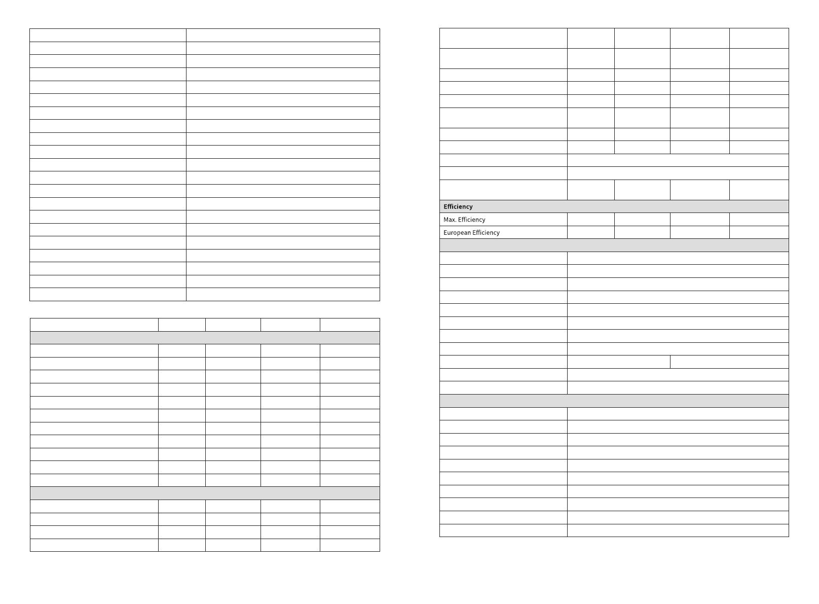
Technical Data GW2500N-XS GW3000N-XS GW3KB-XS GW3300-XS
Input
Max. Input Power (W) 3,250 3,900 3,900 3,900
Max. Input Voltage (V) 600 600 600 500
MPPT Operating Voltage Range (V) 50~550 50~550 50~550 50~450
MPPT Voltage Range at Nominal Power (V) 205~450 245~450 240~450 275~450
Start-up Voltage (V) 50 50 50 50
Nominal Input Voltage (V) 360 360 360 360
Max. Input Current per MPPT (A) 13.0 13.0 13.0 12.5
Max. Short Circuit Current per MPPT (A) 16.3 16.3 16.3 15.6
Max. Backfeed Current to The Array (A) 0 0 0 0
Number of MPP Trackers 1 1 1 1
Number of Strings per MPPT 1 1 1 1
Output
Nominal Output Power (W) 2,500 3,000 3,000 3,300
Nominal Output Apparent Power (VA) 2,500 3,000 3,000 3,300
Max. AC Active Power (W)*1 2,750 3,300 3,300 3,300
Max. AC Apparent Power (VA)*2 2,750 3,300 3,300 3,300
rof ylnO)W( 04 ta rewoP lanimoN
Brazil2,500 3,000 3,000 3,300
Max Power at 40℃ (Including AC
lizarB rof ylnO)W( )daolrevO 2,500 3,000 3,000 3,300
Nominal Output Voltage (V) 220/230 220/230 220 230
Nominal AC Grid Frequency (Hz) 50/60 50/60 60 50/60
Max. Output Current (A) 12.0 14.3 14.3 14.3
Max. Output Fault Current (Peak and
Duration) (A/ms) 30@5ms 30@5ms 30@5ms 30@5ms
Inrush Current (Peak and Duration) (A/us) 50@2us 50@2us 50@2us 50@2us
Nominal Output Current (A) 11.4/10.9 13.6/13.0 13.6/13.0 14.3
Power Factor ~1 (Adjustable from 0.8 leading to 0.8 lagging)
Max. Total Harmonic Distortion <3%
Maximum Output Overcurrent Protection
(A) 32 32 32 32
97.6% 97.6% 97.6% 97.6%
97.2% 97.2% 97.2% 97.2%
Protection
PV Insulation Resistance Detection Integrated
Residual Current Monitoring Integrated
PV Reverse Polarity Protection Integrated
Anti-islanding Protection Integrated
AC Overcurrent Protection Integrated
AC Short Circuit Protection Integrated
AC Overvoltage Protection Integrated
DC Switch Integrated
DC Surge Protection Type III (Type II Optional) Type III
AC Surge Protection Type III
AFCI Optional
General Data
Operating Temperature Range (℃)
Relative Humidity 0~100%
Max. Operating Altitude (m)*3 4000
Cooling Method Natural Convection
User Interface LED, LCD (Optional)WLAN+APP
Communication WiFi, LAN or RS485(Optional)
Communication Protocols Modbus-RTU (SunSpec Compliant)
Weight (kg) 5.8
Dimension (W×H×D mm) 295×230×113
Noise Emission (dB) <42
-25~+60(60 °C for outdoor unconditioned with solar effects.)
  • Page 1 1
  • Page 2 2
  • Page 3 3
  • Page 4 4
  • Page 5 5
  • Page 6 6
  • Page 7 7
  • Page 8 8
  • Page 9 9
  • Page 10 10
  • Page 11 11
  • Page 12 12
  • Page 13 13
  • Page 14 14
  • Page 15 15
  • Page 16 16
  • Page 17 17
  • Page 18 18
  • Page 19 19
  • Page 20 20
  • Page 21 21
  • Page 22 22
  • Page 23 23

Goodwe XS Series Grid-Tied PV Inverter User manual

Type
User manual

Ask a question and I''ll find the answer in the document

Finding information in a document is now easier with AI