Page is loading ...

NO PART LIST QTY
BACK REST 1PC
SIDE PANEL
(L)
FRONT
SIDE RAIL
LEG
ITEM HARDWARE QTY
JCBB SCREW
M8 x 20MM
L - KEY
M5 x 65MM
1PC
1PC
4PCS
16PCS
4PCS
STEP 1
STEP 3
1
2
3
4
5
FREDA DAYBED
6
SIDE PANEL
(R)
Please do not tighten the hardware until the entire assembly is completed.
7SLAT 2 SET
JCBC SCREW
M6 x 40MM
SPRING WASHER
FLAT WASHER
(BIG)
FLAT WASHER
(SMALL)
L - KEY
M4 x 100MM
SCREW
M4 x 32MM
SCREW
M4 x 16MM
4PCS
12PCS
24PCS
16PCS
16PCS
1PC
1PC
A
B
16PCS
JCBC SCREW
M6 x 50MM
C
D
E
F
G
H
I
J
7pcs
BACK
SIDE RAIL
1PC
1PC
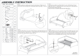
Begin assembly by attaching each Leg (6) to the bottom of the
Side Panel (2) & (3) securing with 2 Allen Bolt (C) per panel using
L-key (I).
STEP 2
Attach the Front Rail (4) and Back Rail (5) to the Side Panel (2) & (3)
aligning holes and securing with 2 Allen Bolts (A) per each end using
L-key (J). (DO NOT FULLY TIGHTEN BOLTS FOR THIS STEP)
Attach the Back Rest (1) to the back of each Side Panel (2) & (3) by
aligning the hole and securing with 2 Allen Bolts (B), 2 Spring Washer
(D), 2 Flat Washer (E) from the back side per each end using L-key (I).
(DO NOT FULLY TIGHTEN BOLTS FOR THIS STEP)
STEP 4
Tighten All Bolts from step 1 to step 4 by using L-key (I) & (J) that has
been provided. Attached Slat (7) to Front Side Rail (4) & Back Side Rail
(5) by unrolling and securing with 6 Screw (H), per set using Phillips
Head Screwdriver.
Repeat the same step to attach another set of Slat (7).
6C I
A J
1
3
EDBI
23
2
4
5
3
1
2
43
8
9
10
11
12
13
1PC
1PC
TRUNDLE
FRONT RAIL
TRUNDLE
BACK RAIL
TRUNDLE
SIDE RAIL 2PCS
SLAT
5pcs
2 SET
SLAT
SUPPORT 3PCS
6PCS
CASTOR
H
7

Please do not tighten the hardware until the entire assembly is completed.
J
1
3
3
2
5
6
3
4
4
TRUNDLE
FULL SET ASSEMBLY
COMPLETE
Assembly by tracing around the Castors (13)
onto the Slats Support (12). Secure Castors (13)
to Slats Support (12) using 4 Screws (G)
per castor.
Tighten screws with Phillips screwdriver
(NOT INCLUDED)
Begin with attaching Trundle Side Rail (10) to Front Rail (8)
& Back Rail (9) using 2 Bolts (A) per corner.
Tighten bolts with Allen Key (J) provided.
Attach Slat Support (12) to Front Rail (8)
& Back Rail (9) using 2 Bolts (C),
2 Spring Washers (D) and 2 Flat
Washer (F) on each end of each
Slat Support (12). Tighten bolts with
Allen Key (I).
Attach Slat (11) to Front Rail (8) & Back
Rail (9) using 4 Screws (H) per set.
Tighten screws with Phillips screwdriver
(NOT INCLUDED)
STEP 5
STEP 7
STEP 6
STEP 8
10
8
9
10
A
J10
8
12
10
9
13
12
G
10
8
10
12
I
C
D
F
811
11
H
/


