Page is loading ...

S4200-ON Series Installation Guide
January 2019
January 2019
Rev. A02

Notes, cautions, and warnings
NOTE: A NOTE indicates important information that helps you make better use of your computer.
CAUTION: A CAUTION indicates either potential damage to hardware or loss of data and tells you how to avoid
the problem.
WARNING: A WARNING indicates a potential for property damage, personal injury, or death.
© 2018 - 2019 Dell Inc. or its subsidiaries. All rights reserved. Dell, EMC, and other trademarks are trademarks of Dell Inc. or its
subsidiaries. Other trademarks may be trademarks of their respective owners.

Chapter 1: About this guide........................................................................................................... 5
Related documents............................................................................................................................................................. 5
Information Symbols........................................................................................................................................................... 6
Chapter 2: S4200-ON series switch...............................................................................................7
Introduction........................................................................................................................................................................... 7
Features................................................................................................................................................................................. 8
Physical dimensions.............................................................................................................................................................8
LED display............................................................................................................................................................................ 8
LED behavior...................................................................................................................................................................9
Prerequisites....................................................................................................................................................................... 10
S4200-ON configurations.................................................................................................................................................11
Luggage tag......................................................................................................................................................................... 11
Chapter 3: Site preparations........................................................................................................ 13
Site selection.......................................................................................................................................................................13
Cabinet placement............................................................................................................................................................. 13
Rack mounting.................................................................................................................................................................... 14
Switch ground.....................................................................................................................................................................14
Fans and airflow................................................................................................................................................................. 14
Power.................................................................................................................................................................................... 14
Component storage...........................................................................................................................................................14
Chapter 4: NEBS compliance....................................................................................................... 16
Important information....................................................................................................................................................... 16
NEBS-compliant ground installation..............................................................................................................................16
Chapter 5: S4200-ON Series installation......................................................................................19
Unpack the switch............................................................................................................................................................. 19
Unpack............................................................................................................................................................................ 19
Rack or cabinet installation.............................................................................................................................................20
ReadyRails Installation......................................................................................................................................................20
Tool-less non-threaded mount installation.............................................................................................................21
Two-post flush-mount installation.......................................................................................................................... 22
Two-post center-mount installation....................................................................................................................... 23
Four-post threaded installation................................................................................................................................ 24
S4200-ON Series switch installation............................................................................................................................25
1U front-rack installation........................................................................................................................................... 25
Ground cable.......................................................................................................................................................................27
Optics installation..............................................................................................................................................................28
Optics removal............................................................................................................................................................. 28
Switch power-up............................................................................................................................................................... 28
After switch installation................................................................................................................................................... 29
Switch replacement..........................................................................................................................................................29
Contents
Contents 3

Chapter 6: Power supplies...........................................................................................................30
Components....................................................................................................................................................................... 30
AC or DC power supply installation............................................................................................................................... 31
AC or DC power supply replacement......................................................................................................................32
Connect DC power supply to power source...............................................................................................................32
Chapter 7: Fans........................................................................................................................... 34
Components........................................................................................................................................................................34
Fan module installation.....................................................................................................................................................35
Fan module replacement............................................................................................................................................35
Fan air filter replacement.......................................................................................................................................... 35
Chapter 8: Management ports..................................................................................................... 37
RS-232 console port access........................................................................................................................................... 37
USB storage mount.......................................................................................................................................................... 38
Before you install an OS.................................................................................................................................................. 38
ONIE service discovery....................................................................................................................................................39
Chapter 9: Specifications............................................................................................................ 41
Chassis physical design.....................................................................................................................................................41
IEEE standards................................................................................................................................................................... 42
Agency compliance........................................................................................................................................................... 43
USA Federal Communications Commission statement............................................................................................ 43
European Union EMC directive conformance statement........................................................................................ 43
Japan VCCI compliance for class A equipment..........................................................................................................44
Korean certification of compliance............................................................................................................................... 44
Electromagnetic compatibility .......................................................................................................................................45
Safety standards and compliance agency certifications......................................................................................... 45
Product recycling and disposal...................................................................................................................................... 45
Chapter 10: Dell EMC support......................................................................................................47
4
Contents

About this guide
This guide provides site preparation recommendations, step-by-step procedures for rack mounting and desk mounting, inserting
modules, and connecting to a power source.
CAUTION: To avoid electrostatic discharge (ESD) damage, wear grounding wrist straps when handling this
equipment.
NOTE: Only trained and qualified personnel can install this equipment. Read this guide before you install and power up this
equipment. This equipment contains two power cords. Disconnect both power cords before servicing.
NOTE: This equipment contains optical transceivers, which comply with the limits of Class 1 laser radiation.
Figure 1. Class 1 laser product tag
NOTE: When no cable is connected, visible and invisible laser radiation may be emitted from the aperture of the optical
transceiver ports. Avoid exposure to laser radiation and do not stare into open apertures.
Regulatory
● Marketing model S4248FB-ON is represented by the regulatory model E22W and the regulatory Type E22W001.
● Marketing model S4248FBL-ON is represented by the regulatory model E22W and the regulatory Type E22W002.
Topics:
• Related documents
• Information Symbols
Related documents
For more information about the S4200-ON Series (S4248FB-ON and S4248FBL-ON), see the following documents:
● OS10 Enterprise Edition Release Notes
● OS10 Enterprise Edition User Guide
● S4200-ON Series Set-up Guide
● Open Networking Hardware Diagnostic Guide
● S4200-ON Series Release Notes
NOTE: For the most recent documentation, visit Dell EMC support: www.dell.com/support.
1
About this guide 5

Information Symbols
This book uses the following information symbols:
NOTE: The Note icon signals important operational information.
CAUTION: The Caution icon signals information about situations that could result in equipment damage or loss
of data.
NOTE: The Warning icon signals information about hardware handling that could result in injury.
NOTE: The ESD Warning icon requires that you take electrostatic precautions when handling the device.
6 About this guide

S4200-ON series switch
The following sections describe the Dell EMC S4200-ON Series (S4248FB-ON and S4248FBL-ON).
Topics:
• Introduction
• Features
• Physical dimensions
• LED display
• Prerequisites
• S4200-ON configurations
• Luggage tag
Introduction
The S4200-ON Series (S4248FB-ON and S4248FBL-ON) is a one rack unit (RU) compact full-featured high-density
10/25/40/100GbE switch. The switch includes 40 small form-factor pluggable plus (SFP+) optics, six quad form-factor
pluggable 28 (QSFP28) optics (100GbE, 4x25GbE, 40GbE, and 4x10GbE), and two QSFP+ optics for 40/100GbE aggregation
and 1/10GbE top-of-rack (ToR) and end-of-row (EoR) applications.
The S4200-ON Series supports the following configurations:
● 48 x 10GbE + 6 x 100GbE
● 40 x 10GbE + 8 x 40GbE
● 48 x 10GbE + 12 x 50GbE
● 48 x 10GbE + 24 x 25GbE
● 72 x 10GbE
● 40 x 10GbE + 2 x 40GbE + 6 x 100GbE
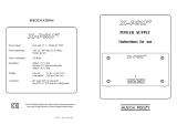
Figure 2. S4200-ON Series I/O-side view
1.
RS-232 console port 2. 40 SFP+ optical ports
3. Two QSFP+ optical ports 4. Six QSFP28 optical ports
5. ESD Jack 6. USB Type A
7. Ethernet management port 8. Luggage tag
2
S4200-ON series switch 7

Figure 3. S4200-ON Series PSU-side view
1. Five hot-swappable fan units
2. Two hot-swappable PSUs with integrated fans
Features
The S4200-ON Series (S4248FB-ON and S4248FBL-ON) offers the following features:
● Forty 1/10GbE fixed SFP+ ports
● Two QSFP+ ports supporting 40GbE or 4x10GbE breakout
● Six QSFP28 ports
● One RJ-45 console port
● One USB Type-A 2.0 port for additional file storage
● One ESD Jack
● TCAM: on-board Rangeley central processing unit (CPU) system with 32GB DDR III RAM, 64GB iSLC mSATA SSD
● Non-TCAM: on-board Rangeley CPU system with 8GB DDR III RAM, 16GB iSLC mSATA SSD
● Two hot-swappable redundant power supplies
● Five hot-swappable fans modules
● Standard 1U switch
Physical dimensions
The S4200-ON Series (S4248FB-ON and S4248FBL-ON) has the following physical dimensions:
● 434 x 462 x 44 mm (W x D x H)
● 17.1 x 18.2 x 1.72 inches (W x D x H)
● PSU and fan module Handle: 1.57 inches (40 mm)
LED display
The S4200-ON Series (S4248FB-ON and S4248FBL-ON) includes LED displays on the I/O side of the switch.
For more LED information, see your third-party operating software documentation.
8
S4200-ON series switch

LED behavior
The following S4200-ON Series (S4248FB-ON and S4248FBL-ON) switch LED behavior displays during open networking
installation environment (ONIE) operations:
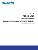
Figure 4. S4200-ON Series LEDs
1.
System LED 2. Locator LED
3. Link Port LED 4. Activity Port LED
5. QSFP28 Port LED 6. RJ-45 Ethernet Port LED: Left is link; right is activity.
7. Fan LED 8. Power LED
Table 1. S4200-ON series LED behavior
LED Description
System Status/Health LED
● Solid green—Normal Operation
● Blinking green—Booting
● Solid yellow—Critical system error
● Blinking yellow—Noncritical system error, fan failure, or
power supply failure
Power LED
● Off—No power
● Solid green—Normal
● Solid yellow—POST is in process
● Blinking yellow—Power supply failed
FAN LED
● Solid green—Fan powered and running at the expected
RPM
● Blinking yellow—Fan failed, including incompatible airflow
direction when you insert the PSU or fan trays with
differing airflows
● Off—No power
LOCATOR LED/System beacon
● Off—Locator function is disabled
● Blinking blue—Locator function is enabled
RJ-45 Ethernet LED
● Off—no link and no activity detected
● On—Activity on the port
● Solid yellow—10MHz activity
● Solid green—100MHz activity
● Blinking green—1GHz activity
S4200-ON series switch 9

Table 2. Management Ethernet port LEDs
LED Description
Link LED
● Off—No Link
● Solid green—Link operating at a maximum speed,
autonegotiated/forced or 1G
● Solid yellow—Link operating at a lower speed,
autonegotiated/forced or 10/100M
Activity LED
● Off—No Link
● Flashing green—Port activity
Table 3. SFP+ port LEDs
LED Description
Link LED
● Off—No Link
● Solid green—Link operating at maximum speed, 10G
● Solid yellow — Link operating at a lower speed, 1G
● Flashing yellow, 1 second on/off—Port beacon
Activity LED
● Off—No Link
● Flashing green—Port activity
NOTE: There are four LEDs for each QSFP+ and QSFP28 port. For each port, 100GbE or 40GbE uses only one LED,
2x50GbE uses two LEDs, and 4x25GbE or 4x10GbE uses all four LEDs.
Table 4. QSFP+ and QSFP28 port LEDs
LED Description
Link/Activity LED
● Off—No Link
● Flashing green—Port activity operating at maximum
speed, 100G for QSFP28 ports or 40G for QSFP+ ports
● Flashing yellow—Port activity operating at a lower speed
● Flashing yellow, 1 second on/off—Port beacon
Link/Activity LED—4x25G mode or 4x10G mode
● Off—No Link
● Flashing green—Port activity at 4x25G on a QSFP28 port
or 4x10G on a QSFP+ port
● Flashing yellow—Port activity at 4x10G on a QSFP28 port
● Flashing yellow, 1 second on/off—Port beacon
Link/Activity LED—2x50G
● Of —No Link
● Flashing yellow—Port activity at 2x50G on a QSFP28 port
● Flashing yellow, 1 second on/off—Port beacon
Prerequisites
The following is a list of required and optional components for the S4200-ON Series (S4248FB-ON and S4248FBL-ON) switch:
NOTE:
Detailed installation instructions for the S42400-ON Series are provided in Site Preparations and Install the S4200-
ON Series.
● S4200-ON Series (S4248FB-ON or S4248FBL-ON) switch or multiple switches, if stacking
● AC country- and regional-specific cables to connect the AC power source to each of the switches’ AC power supplies
● Mounting brackets for rack installation, included
● Screws for rack installation
● #1 and #2 Phillips screw drivers, not included
10
S4200-ON series switch

● Torx screwdriver, not included
● Ground cable screws, included
● Copper or fiber cables
Other optional components are:
● Ground cable and lug for the frame-end of the ground cable
● Extra power supply unit
● Extra fan module
● Extra mounting brackets if installing in a four-post rack or cabinet
S4200-ON configurations
You can order the S4200-ON Series (S4248FB-ON and S4248FBL-ON) switch in several different configurations.
● S4248FB–ON or S4248FBL-ON AC normal airflow: Forty 1/10GbE SFP+ ports, two 40GbE or 4x1/10GbE QSFP+, and six
100/40GbE or 4x25/10GbE or 2x50GbE QSFP28 ports, two AC power supplies, and five fan subsystems with airflow from
the I/O side to the power supply side
● S4248FB–ON or S4248FBL-ON AC reverse airflow: Forty 1/10GbE SFP+ ports, two 40GbE or 4x1/10GbE QSFP+, and six
100/40GbE or 4x25/10GbE or 2x50GbE QSFP28 ports, two AC power supplies, and five fan subsystems with airflow from
the power supply side to the I/O side
● Fan with airflow from the I/O side to the PSU side
● Fan with airflow from the PSU side to the I/O side
● AC Power supply with airflow from the I/O side to the PSU side—normal
● AC Power supply with airflow from the PSU side to the I/O side—reverse
● DC Power supply with airflow from the I/O side to the PSU side—normal
● DC Power supply with airflow from the PSU side to the I/O side—reverse
Luggage tag
The S4200-ON Series (S4248FB-ON and S4248FBL-ON) switch has a pull-out tag, known as a luggage tag, on the I/O-side of
the switch. The front of the luggage tag includes switch ID information. The back of the luggage tag includes a QRL that takes
you to a Dell EMC How-To site where you can watch videos about racking the switch, replacing components, configuring port
channels, and so on.
S4200-ON series switch
11

Figure 5. S4200-ON Series luggage tag
1.
SVC Tag 2. MAC Address
3. PPID 4. Express Service Code
12 S4200-ON series switch

Site preparations
The S4200-ON Series (S4248FB-ON and S4248FBL-ON) switch is suitable for installation as part of a common bond network
(CBN).
You can install the switch in:
● Network telecommunication facilities
● Data centers
● Other locations where the National Electric Code (NEC) applies
For more information about switch specifications, see Specifications.
NOTE: Install the S4200-ON Series switch in a rack or cabinet before installing any optional components.
Topics:
• Site selection
•
Cabinet placement
• Rack mounting
• Switch ground
• Fans and airflow
• Power
• Component storage
Site selection
Install Dell EMC equipment in restricted access areas.
A restricted access area is one in which service personnel can only gain access using a special tool, lock, key, or other means of
security. The authority responsible for the location controls access to the restricted area.
Ensure that the area where you install your S4200-ON Series switch meets the following safety requirements:
● Near an adequate power source. Connect the switch to the appropriate branch circuit protection according to your local
electrical codes.
● Switch environmental temperature range is from 0° to 45°C (32° to 113°F).
● Relative humidity is from 5 to 90 percent noncondensing.
● In a dry, clean, well-ventilated and temperature-controlled room, away from heat sources such as hot air vents or direct
sunlight.
● Away from sources of severe electromagnetic noise.
● Inside the restricted access area, positioned in a rack or cabinet, or on a desktop with adequate space in the front, back, and
sides for proper ventilation and access.
● Install the switch in Information Technology Rooms in accordance with Article 645 of the National Electrical Code and NFPA
75.
For more information about switch storage and environmental temperatures, see Specifications.
Cabinet placement
Install the S4200-ON Series (S4248FB-ON and S4248FBL-ON) switch only in indoor cabinets designed for use in a controlled
environment.
Do not install the switch in outside cabinets. For cabinet placement requirements, see Site Selection.
The cabinet must meet minimum size requirements. Airflow must be in accordance with the Electronic Industries Alliance (EIA)
standard. Ensure that there is a minimum of 5 inches (12.7 cm) between the intake and exhaust vents and the cabinet wall.
3
Site preparations 13

Rack mounting
When you prepare your equipment rack, ensure that the rack is grounded.
Ground the equipment rack to the same ground point the power service in your area uses. The ground path must be permanent.
Switch ground
Dell EMC recommends grounding your switch. Use the S4200-ON Series switch in a CBN.
Connect the grounding cables as described in S4200–ON Series Installation.
Fans and airflow
The S4200-ON Series (S4248FB-ON and S4248FBL-ON) switch fans support two airflow options: normal and reverse.
Fan combinations
Installation of the fans is done as part of the factory install based on stock keeping unit (SKU) type. The S4200-ON Series has
SKUs that support the following configurations:
● AC or DC PSU with fan airflow from the I/O to the PSU—the red indicator is the normal airflow.
● AC or DC PSU with fan airflow from the PSU to the I/O—the blue indicator is the reverse airflow.
Be sure to order the fans suitable to support your site’s ventilation. Use a single type of airflow fan in your switch. Do not mix
reverse and normal airflows in a single S4200-ON Series switch.
For proper ventilation, position the switch in an equipment rack (or cabinet) with a minimum of 5 inches (12.7 cm) of clearance
around the exhaust vents. When you install two S4200-ON Series switches near each other, to permit proper airflow, position
the two switches at least 5 inches (12.7 cm) apart. The fan speed varies based on internal temperature monitoring. The S4200-
ON Series never intentionally turns off the fans.
For more information, see Fans.
Power
Use the appropriate power cord with the S4200-ON Series (S4248FB-ON and S4248FBL-ON) when connecting the switch to
the power source. An AC power cord is included with each PSU.
When installing AC or DC switches, follow the requirements of the National Electrical Code ANSI/NFPA 70, where applicable.
The switch is powered-up when the power cord is connected between the switch and the power source. For more information,
see Power Supplies.
CAUTION:
Always disconnect the power cable before you service the power supply slots. The switch has
multiple power cords. Before servicing, ensure all power cords are disconnected.
CAUTION: Use the power supply cord as the main disconnect device on the AC switch. Ensure that the socket-
outlet is located/installed near the equipment and is easily accessible.
NOTE: Module power is software controlled. You do not see module LEDs when the switch powers up in ONIE.
Component storage
If you do not install your S4200-ON Series (S4248FB-ON and S4248FBL-ON) switch and components immediately, properly
store the switch and all optional components by following these guidelines:
● Storage location temperature must remain constant. The storage range is from -40°C to 70°C (-40°F to 158°F).
14
Site preparations

● Store on a dry surface or floor, away from direct sunlight, heat, and air conditioning ducts.
● Store in a dust-free environment.
NOTE: ESD damage can occur when components are mishandled. Always wear an ESD-preventive wrist or heel ground
strap when handling the S4200-ON Series switch and its accessories. After you remove the original packaging, place the
S4200-ON Series switch and its components on an anti-static surface.
Site preparations 15

NEBS compliance
For your switch to be network equipment building system (NEBS) compliant, you must follow the instructions detailed in this
section.
To be NEBS compliant, orient your switch in the rack so that the air inlet is from the front aisle and the air exhaust is to the
back aisle.
Topics:
• Important information
• NEBS-compliant ground installation
Important information
WARNING: The SFP+, QSFP, QSFP28, console, Ethernet management, and universal serial bus (USB) ports are
suitable for connection to intrabuilding or unexposed wiring or cabling only. You MUST NOT metallically connect
the ports to interfaces that connect to the out side plant (OSP) or its wiring. Use these interfaces as
intrabuilding interfaces only (Type-2 or Type-4 ports as described in GR-1089-CORE, Issue 6) and they require
isolation from the exposed OSP cabling. Adding primary protectors is not sufficient protection to connect these
interfaces metallically to OSP wiring.
WARNING: If you install and connect the S4200-ON Series (S4248FB-ON and S4248FBL-ON) switch to a
commercial AC power source, you must connect the switch to an external special protection device (SPD).
To be NEBs compliant:
● Locate your switch in a restricted-access area were only trained personnel are allowed access.
● Install and connect your switch to the common bonding network (CBN).
● You can also install and connect your switch to the central office.
● Connect the battery returns of your switch as DC-I.
● Ground your switch using a copper ground conductor.
● Clean and coat all bare grounding connection points on your switch with an antioxidant solution before making connections.
● Bring all unplated ground connection surfaces on your switch to a bright finish and treat them with an antioxidant solution
before making connections.
● To ensure electrical continuity, remove any nonconductive surfaces on your switch from the ground connection points and
threaded holes used to secure the ground lugs.
● Use the two-hole, Listed, compression-type lug with an AWG 14 gauge wire for switch grounding.
NOTE: The S4200-ON Series can operate at -40.5 VDC to -60 VDC at a maximum current level of 15A.
NOTE: The S4200-ON Series is Earthquake Z4-compliant when you attach the ReadyRails to the frame using threaded
hardware. Do not use tool-less installation method.
NEBS-compliant ground installation
Before you install the switch into a rack, install the ground (GND) lug assembly.
Your switch includes an assembled UL-certified GND lug with bracket, packaged separately. If any parts are missing, contact
your Dell EMC sales representative.
4
16 NEBS compliance

Figure 6. GND lug assembly
1. Remove the two installed M3 screws from the lower-left side of your switch.
NOTE: Keep these screws.
2. Remove the bracket assembly from the shipping bag.
3. Clean the bracket and lug surfaces thoroughly and apply an anti-oxidant solution to the mating surfaces.
4. Attach the switch ground using the Ground cable instructions.
5. Using the two removed screws, attach the GND lug bracket assembly to your switch, as shown.
Torque the M3 screws to ±4-5 in-lbs.
Figure 7. Attach the GND lug assembly
NEBS compliance
17


S4200-ON Series installation
To install the S4200-ON Series (S4248FB-ON and S4248FBL-ON) switch, complete the installation procedures in the order
presented in this section.
Always handle the switch and its components with care. Avoid dropping the switch or its field replaceable units (FRUs).
NOTE: ESD damage can occur if components are mishandled. Always wear an ESD-preventive wrist or heel ground strap
when handling the S4200-ON Series and its components. As with all electrical devices of this type, take all the necessary
safety precautions to prevent injury when installing this switch.
Topics:
• Unpack the switch
• Rack or cabinet installation
• ReadyRails Installation
• S4200-ON Series switch installation
• Ground cable
• Optics installation
• Switch power-up
• After switch installation
• Switch replacement
Unpack the switch
NOTE: Before unpacking the switch, inspect the container and immediately report any evidence of damage.
When unpacking the S4200-ON Series (S4248FB-ON and S4248FBL-ON) switch, make sure that the following items are
included:
● One S4200-ON Series (S4248FB-ON or S4248FBL-ON) switch
● One RJ-45 to DB-9 female cable
● Two sets of rail kits, no tools required
● Two PSUs and power cords
● Five fan units
● Two country- and region-specific AC power cords
● S4200-ON Series Set-up Guide
● Safety and Regulatory Information
● Warranty and Support Information
Unpack
1. Place the container on a clean, flat surface and cut all straps securing the container.
2. Open the container or remove the container top.
3. Carefully remove the switch from the container and place it on a secure and clean surface.
4. Remove all packing material.
5. Inspect the product and accessories for damage.
5
S4200-ON Series installation 19

Rack or cabinet installation
You may either place the switch on a rack shelf or mount the switch directly into a 19" wide, EIA-310- E-compliant rack. Rack
mounting includes four-post, two-post, round threaded holes, or square holes. The ReadyRails system is provided for 1U front-
rack and two-post installations.
The ReadyRails system includes two separately packaged rail assemblies. To begin installation, separate each rail assembly by
sliding the inside rail out of the outside rail.
CAUTION: Your switch is not NEBS Earthquake Z4-compliant if you use the 1U tool-less square-hole or two-post
installation methods.
WARNING: This document is a condensed reference. Read the safety instructions in your
Safety, Environmental,
and Regulatory
information booklet before you begin.
NOTE: The illustrations in this section are not intended to represent a specific switch.
NOTE: Do not the use the mounted ReadyRails as a shelf or a workplace.
Rack mount safety considerations
● Rack loading—Overloading or uneven loading of racks may result in shelf or rack failure, possibly damaging the equipment
and causing personal injury. Stabilize racks in a permanent location before loading begins. Mount the components starting at
the bottom of the rack, then work to the top. Do not exceed your rack’s load rating.
● Power considerations—Connect only to the power source specified on the unit. When you install multiple electrical
components in a rack, ensure that the total component power ratings do not exceed the circuit capabilities. Overloaded
power sources and extension cords present fire and shock hazards.
● Elevated ambient temperature—If you install the switch in a closed rack assembly, the operating temperature of the rack
environment may be greater than the room ambient temperature. Use care not to exceed the 45°C maximum ambient
temperature of the switch.
● Reduced air flow—Do not compromise the amount of airflow required for safe operation of the equipment. Install the
equipment in the rack so that the equipment constantly has the correct amount of airflow surrounding it.
● Reliable earthing—Maintain reliable earthing of rack-mounted equipment. Pay particular attention to the supply connections
other than the direct connections to the branch circuit, for example: use of power strips.
● Do not mount the equipment with the fan panel facing downward.
ReadyRails Installation
To easily configure your rack for installation of your S4200-ON Series (S4248FB-ON and S4248FBL-ON) switch, use the
ReadyRails rack mounting system provided.
You can install the ReadyRails system using the 1U tool-less square-hole method or one of three possible 1U threaded round-hole
methods—2-post flush mount, 2-post center mount, or 4-post mount.
CAUTION:
Your switch is not NEBS Earthquake Z4-compliant if you use the 1U tool-less square-hole installation
method.
To begin installation, separate each rail assembly by sliding the inside rail out of the outside rail.
NOTE: For more installation instructions, see the installation labels attached to the rail assembly.
20 S4200-ON Series installation
/