Greenheck 464236 AFB, AFBUP, FSAF, FSNF, NFB Series Actuators External Mount Operating instructions
- Type
- Operating instructions

These instructions apply to the external field installation of Belimo actuators on Greenheck model VCD Control
Dampers.
These models are direct drive actuators that rotate to their energized position when power is applied, and spring
return to their fail position when power is disconnected.
Tools Required:
Wrenches:
(1)
3
⁄8 in., (1)
7
⁄16 in., and (1) 10mm
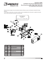
Item Part Description Qty
1 - Belimo actuator (representation) 1
2 723089 Anti-rotation bracket 1
3 815027 Standoff bracket assembly 1
4 415475
1
⁄4-20 x
1
⁄2 in. bolt 4
5 415455
1
⁄4-20 spinlock nut 4
6 415586 #14 TEK screw 4
7 417279 Anti-rotation pin 1
8 415934 Keps hex nut zp 1
®
Belimo Actuators 1
®
Document 464236
Installation Instructions for Belimo Actuators
Direct Drive Series (AFB, AFBUP, FSAF, FSNF, NFB)
UL Listed Direct Drive Actuator

Instructions:
These installation instructions assume the damper is already mounted in a duct or sleeve with the damper shaft
extending beyond the duct or sleeve 6 inches.
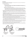
1. Install the stand off bracket.
Dampers with a jackshaft
1a. Jackshaft supplied is typically 1 in. (25mm) diameter. For these applicaitons the bearing must be
removed from the stand-off bracket (item 3). Mount the stand-off bracket (item 3) with (4) thread studs
and (4)
1
⁄4 -20 spinlock screws.
Dampers without a jackshaft (Shaft Extension)
1b. Mount the stand off bracket (item 3) spanning across the damper frame flanges. Orient the anchor
bracket perpendicular to the damper on the duct or sleeve so that the bracket shaft hole is centered on
the shaft extension. Fasten to the damper frame with (4) #14 Tek screws (item 6) or equal, supplied by
others. Be sure not to run the screws into the damper linkage, which is between the flanges.
2. If the fail rotation of the damper is counter clockwise, this is a Left Hand installation and the universal clamp
should be on the side labeled CCW on the actuator (usually shipped in this orientation). If the fail rotation of the
damper is clockwise, this is a Right Hand installation and the universal clamp should be on the side labeled CW
on the actuator.
To change the universal clamp from one side to the other side, remove the retaining clamp and then the universal
clamp from the actuator. Replace the universal clamp on the correct side of the actuator making sure that the
corresponding tab is pointing to 0° and the spline pattern of the clamp fits onto the actuator. Slip the clamp on and
then lock in place using the retaining clamp.
Note: All fail rotations refer to the damper shaft rotation needed to achieve the desire blade fail position. If fail
position is closed, make sure damper blades are fully close and ensure blade seals are compressed prior to
tightening the actuator clamp to the damper extension pin or jackshaft. Inspect the damper blades and the damper
shaft to determine the proper damper shaft rotation for the desired blade fail position.
3. Slide the actuator and the mounting bracket onto the damper shaft making sure the anti-rotation strap is in the
slot on the actuator. Mount the mounting bracket to the stand off bracket using (4)
1
⁄4 in.-20 x
1
⁄2 in. bolts and (4)
1
⁄4 in. - 20 Spinlock nuts, included with this kit. Use the outer four holes of the mounting bracket for jackshafted
models and the inner four holes for directly driven models.
Note: The mounting bracket may be attached in three positions: parallel with the duct, perpendicular up from the
duct, or perpendicular down from the duct. Choose a position that offers the most clearance for the application.
4. Verify that the damper is in its fail position. Tighten the universal clamp to the damper shaft.
5. The wiring illustration to the right identifies actuator electrical connections. Wiring should be per an approved
project or job wiring diagram and must comply with all applicable electrical codes.
6. Apply power to the actuator. The damper blades should fully open or close and return to the fail position when
power is disconnected. No adjustments are required.
Orientation of Stand
Off Bracket for
a directly driven
damper
Orientation of Stand
Off Bracket for a
jackshaft driven
damper
Black
White
120 Volt o
r
24 volt
M
Wiring Illustration
Wiring Illustration
Belimo Actuators 2
®

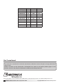
Model Volts Running Holding
AFBUP (-S) 24-240 7W 3.5W
AFB24-MFT (-S) 24 7.5W 3W
AFB24-SR (-S) 24 5.5W 3W
FSAF-24 (-S) 24 7.5W 2W
FSAF-120 (-S) 120 9.5W 3.5W
FSAF-230 (-S) 230 11W 3.5W
FSAFB24-SR (-S) 24 6W 3W
FSNF-24 (-S) 24 18W 6W
FSNF-120 (-S) 120 18W 6W
FSNF-230-S 230 18W 6W
NFB24-SR (-S) 24 3.5W 2.5W
464236 • Belimo Actuators, Rev. 9, September 2020 Copyright 2020 © Greenheck Fan Corporation3
As a result of our commitment to continuous improvement, Greenheck reserves the right to change specifications
without notice.
Product warranties can be found online at Greenheck.com, either on the specific product page or in the
literature section of the website at Greenheck.com/Resources/Library/Literature.
®
Phone: 715.359.6171 • Fax: 715.355.2399 • Parts: 800.355.5354 • E-mail: [email protected] • Website: www.greenheck.com
Our Commitment
-
 1
1
-
 2
2
-
 3
3


Greenheck 464236 AFB, AFBUP, FSAF, FSNF, NFB Series Actuators External Mount Operating instructions
- Type
- Operating instructions
Ask a question and I''ll find the answer in the document
Finding information in a document is now easier with AI
Related papers
-
Greenheck 452583 Damper Guard Operating instructions
-
-
-
-
-
-
-
-
-
Other documents
-
321 Studios Belimo FSAF24 User manual
-
Greenheck Fan WD Series User manual
-
-
-
-
Reznor RECB Operating instructions
-
tekmar Belimo Actuator M3062 Installation guide
-
 Burg sPinLock510 Owner's manual
-
-
Carrier 33ZCFANTRM User manual
