Carrier 33ZCFANTRM User manual
- Category
- Thermostats
- Type
- User manual
This manual is also suitable for

Manufacturer reserves the right to discontinue, or change at any time, specifications or designs without notice and without incurring obligations.
PC 111 Catalog No. 533-355 Printed in U.S.A. Form 33ZC-1SI Pg 1 303 11-99 Replaces: New
Book 1 4
Ta b 1 1 a 1 3 a
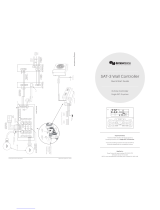
Installation, Start-Up and
Configuration Instructions
Part Numbers 33ZCFANTRM, 33ZCVAVTRM, 33ZCSECTRM
CONTENTS
Page
SAFETY CONSIDERATIONS
. . . . . . . . . . . . . . . . . . . . . . 1
GENERAL
. . . . . . . . . . . . . . . . . . . . . . . . . . . . . . . . . . . . . . . . 2
INSTALLATION
. . . . . . . . . . . . . . . . . . . . . . . . . . . . . . . . 2-29
General
. . . . . . . . . . . . . . . . . . . . . . . . . . . . . . . . . . . . . . . . . . 2
Zone Controller Hardware
. . . . . . . . . . . . . . . . . . . . . . . . 2
Field-Supplied Hardware
. . . . . . . . . . . . . . . . . . . . . . . . . 2
• SPACE TEMPERATURE SENSOR
• PRIMARY AIR TEMPERATURE SENSOR
• SUPPLY AIR TEMPERATURE (SAT) SENSOR
• RELATIVE HUMIDITY SENSOR
• INDOOR AIR QUALITY (CO
2
) SENSOR
Mount Zone Controller
. . . . . . . . . . . . . . . . . . . . . . . . . . . 4
• LOCATION
• MOUNTING
Connect the Power Transformer
. . . . . . . . . . . . . . . . . . 7
Connect Airflow Pickups
. . . . . . . . . . . . . . . . . . . . . . . . . 7
Install Sensors
. . . . . . . . . . . . . . . . . . . . . . . . . . . . . . . . . . 19
• SPACE TEMPERATURE SENSOR INSTALLATION
• PRIMARY AIR TEMPERATURE SENSOR
INSTALLATION
• SUPPLY AIR TEMPERATURE (SAT) SENSOR
INSTALLATION
• INDOOR AIR QUALITY SENSOR INSTALLATION
• HUMIDITY SENSOR (WALL-MOUNTED)
INSTALLATION
Remote Occupancy Contact
. . . . . . . . . . . . . . . . . . . . . 26
Connect the Outputs
. . . . . . . . . . . . . . . . . . . . . . . . . . . . 26
Modulating Baseboard Hydronic Heating
. . . . . . . . 26
Connect the CCN Communication Bus
. . . . . . . . . . 26
• COMMUNICATION BUS WIRE SPECIFICATIONS
• CONNECTION TO THE COMMUNICATION BUS
START-UP
. . . . . . . . . . . . . . . . . . . . . . . . . . . . . . . . . . . . 29-31
Perform System Check-Out
. . . . . . . . . . . . . . . . . . . . . 29
Network Addressing
. . . . . . . . . . . . . . . . . . . . . . . . . . . . . 30
Initial Operation and Test
. . . . . . . . . . . . . . . . . . . . . . . . 30
Airflow Check
. . . . . . . . . . . . . . . . . . . . . . . . . . . . . . . . . . . 30
Fan and Heat Configuration and Test
. . . . . . . . . . . . 30
CONFIGURATION
. . . . . . . . . . . . . . . . . . . . . . . . . . . . 31-50
Points Display Screen
. . . . . . . . . . . . . . . . . . . . . . . . . . . 31
Modify Controller Configuration
. . . . . . . . . . . . . . . . . 32
• ALARM LIMIT CONFIGURATION SCREEN
• CONTROLLER IDENTIFICATION SCREEN
• HOLIDAY CONFIGURATION SCREENS
• LINKAGE COORDINATOR CONFIGURATION
SCREEN
• OCCUPANCY CONFIGURATION SCREEN
• SET POINT SCREEN
Service Configuration Selection Screen
. . . . . . . . . 37
• AIRFLOW SERVICE CONFIGURATION SCREEN
• TERMINAL SERVICE CONFIGURATION SCREEN
• OPTIONS SERVICE CONFIGURATION SCREEN
• SECONDARY DAMPER SERVICE
CONFIGURATION SCREEN
Maintenance Table Menu Screen
. . . . . . . . . . . . . . . . 43
• LINKAGE MAINTENANCE TABLE
• OCCUPANCY MAINTENANCE TABLE
• ZONE AIR BALANCE/COMMISSIONING TABLE
• ZONE MAINTENANCE TABLE
SAFETY CONSIDERATIONS
SAFETY NOTE
Air-handling equipment will provide safe and reliable
service when operated within design specifications. The
equipment should be operated and serviced only by
authorized personnel who have a thorough knowledge
of system operation, safety devices and emergency
procedures.
Good judgement should be used in applying any manu-
facturer’s instructions to avoid injury to personnel or dam-
age to equipment and property.
Disconnect all power to the unit before performing mainte-
nance or service. Unit may automatically start if power is
not disconnected. Electrical shock and personal injury
could result.
If it is necessary to remove and dispose of mercury contac-
tors in electric heat section, follow all local, state, and fed-
eral laws regarding disposal of equipment containing
hazardous materials.
Single Duct Air Terminal Zone Controller
VAV Fan Terminal Zone Controller
Secondary Terminal Zone Controller

2
GENERAL
The zone controller is a single duct, fan powered, Variable
Air Volume (VAV) terminal control with a factory-integrated
controller and actuator. The zone controller maintains precise
temperature control in the space by operating the terminal fan
and regulating the flow of conditioned air into the space. Build-
ings with diverse loading conditions can be supported by con-
trolling reheat or supplemental heat.
The VAV Fan Terminal Zone Controller (33ZCFANTRM)
provides dedicated control functions for series fan or parallel
fan powered terminals, single duct terminals with 3 stages of
heat, or as a primary controller for dual duct or zone pressure
control applications.
The Single Duct Air Terminal Zone Controller
(33ZCVAVTRM) provides dedicated control functions for sin-
gle duct terminals with modulating heat or up to 2 stages of
heat.
When the VAV Fan Terminal Zone Controller is used in
conjunction with a secondary terminal and the 33ZCSECTRM
secondary terminal zone controller, either dual duct or zone
pressurization applications can be supported.
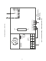
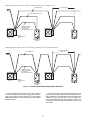
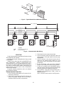
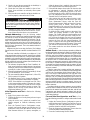
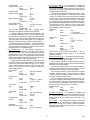
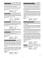
Carrier’s Linkage system is an integrated combination of
Carrier Comfort Network (CCN) controllers for use with Sin-
gle Duct air terminals and VAV Fan Powered terminals. The
Single Duct air terminal and VAV Fan terminal zone control-
lers are part of the Carrier ComfortID system.
Devices manufactured by Carrier which have Product Inte-
grated Controls on the same communication bus as the zone
controller, air handlers (such as the 39L,T), or large rooftop
units do not require an external controller to function as part of
a Carrier linkage system. These air handlers or large rooftop
units feature factory-installed Product Integrated Control (PIC)
controllers that are directly compatible with the system. Con-
sult your local Carrier representative for the complete list of
compatible air handlers. The Comfort System AirManager
(CSAM) or the CC6400 supports linkage for non-Carrier de-
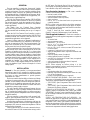
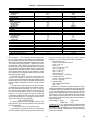
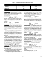
vices or air handlers. Figure 1 shows an example of a Carrier
linkage system.
INSTALLATION
General —
The zone controller is a microprocessor-based
direct digital control (DDC) controller for variable air volume
(VAV) air terminals. It can be retrofitted on units manufactured
by Carrier or other manufacturers to provide pressure-
independent VAV control.
Each zone controller has the ability to function as a linkage
coordinator for systems with up to 128 zones. As a linkage co-
ordinator, a zone controller will retrieve and provide system in-
formation to the air handling equipment and other zone con-
trollers. A zone controller can function as a stand alone device
by installing a primary supply air sensor.
The zone controller monitors differential pressure from an
airflow pickup (or a pair of pickups) mounted on the terminal
box. It compares the resulting signal to an airflow set point in
order to provide pressure-independent control of the air passing
through the terminal.
The zone controller is connected to a wall-mounted, field-
supplied, space temperature sensor (SPT) in order to monitor
zone temperature changes and satisfy zone demand.
On stand-alone applications or applications with heat, the
zone controller must be connected to a field-supplied supply air
temperature (SAT) sensor to monitor the temperature of the air
delivered by the air terminal.
Carrier’s Network Service Tool can be connected to the sys-
tem at the SPT sensor if CCN communication wiring is run to
the SPT sensor. The Network Service Tool can be used to ad-
just set points, set operating parameters, and fully configure the
zone controller or any device on the system.
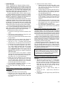
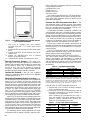
Zone Controller Hardware —
The zone controller
consists of the following hardware:
• terminal control module
• torque-limiting damper actuator
• airflow transducer (velocity sensor)
• plastic enclosure
• one no. 8 x
1
/
2
-in. sheet metal screw (to prevent zone
controller rotation)
NOTE: A filter is not provided for the airflow transducer.
For installations on systems with a high degree of impuri-
ties, an air filter can be purchased and installed on the trans-
ducer high pressure pickup.
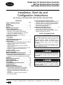
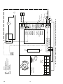
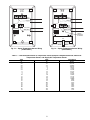
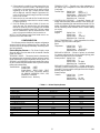
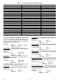
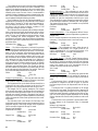
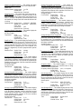
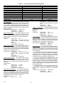
Figure 2 shows the zone controller physical details.
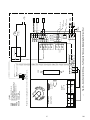
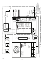
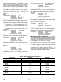
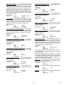
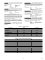
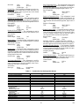
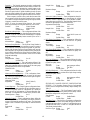
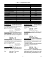
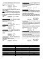
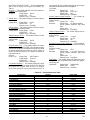
Figures 3-5 show the 3 different types of zone controllers.
Field-Supplied Hardware —
Each zone controller re-
quires the following field-supplied components to complete its
installation:
• air terminal unit
• space temperature sensor
• transformer — 24 vac, 40 va
• two no. 10 x
1
/
2
-in. sheet metal screws (to secure SAT
sensor to duct, if required)
• two no. 6-32 x
5
/
8
-in. screws (to mount SPT sensor base
to electrical box)
• contactors (if required for fan or electric heat)
• supply air temperature sensor (required for terminal with
ducted heat)
• indoor air quality sensor (if required)
• relative humidity sensor (if required)
• one SPST (for each stage of electric heat, not required
for Carrier fan terminals)
• valve and actuator for hot water heat (if required)
• delta pressure airflow pickup
NOTE: When selecting an airflow pickup, it is the
designer's responsibility to select a sensor that provides the
desired output at the design airflow.
•wire
• polyethylene tubing (for pressure pickup)
• bushings (required when mounting SAT sensor in a duct
6-in. or less in diameter)
• primary air temperature sensor (if required)
SPACE TEMPERATURE SENSOR — Each zone control-
ler requires a field-supplied Carrier space temperature sensor.
There are two sensors available for this application:
• 33ZCT55SPT, Space Temperature Sensor with Override
Button
• 33ZCT56SPT, Space Temperature Sensor with Override
Button and Set Point Adjustment
PRIMARY AIR TEMPERATURE SENSOR — A field-
supplied, primary air temperature (PAT) sensor (part number
33ZCSENPAT) is used on a zone controller which is function-
ing as a Linkage Coordinator for a non CCN/Linkage compati-
ble air source.
SUPPLY AIR TEMPERATURE (SAT) SENSOR — On
stand-alone applications or applications with ducted heat, the
zone controller must be connected to a field-supplied supply air
temperature (SAT) sensor (part number 33ZCSENSAT) to
monitor the temperature of the air delivered by the air terminal.
The zone controller will maintain the air temperature below the
maximum air temperature in ducted heating applications.

3
CCN PRIMARY BUS (BUS 0)
FULLY
COMPATIBLE
AIR HANDLER
CC6400 OR CSAM
EQUIPPED
NON-CCN
AIR HANDLER
COMFORTID
EQUIPPED
AIR TERMINAL
(1 OF UP TO 128)
ADDRESSED
SEQUENTIALLY
SECONDARY BUS
DATA
COLLECTION
OPTION
BRIDGE
(RECOMMENDED)
SYSTEM
MONITORING
SOFTWARE
CCN
LEGEND
Fig. 1 — Typical Carrier Linkage System
CCN —
Carrier Comfort Network
CSAM —
Comfort System
Air
Manager

4
RELATIVE HUMIDITY SENSOR — The
33AMSENRHS000 relative humidity sensor is required for
zone humidity control (dehumidification).
NOTE: The relative humidity sensor and CO
2
sensor cannot
be used on the same zone controller.
INDOOR AIR QUALITY (CO
2
) SENSOR — An indoor air
quality sensor is required for optional demand control ventila-
tion. The CGCDXSEN002A00 CO
2
Sensor is an indoor,
wall mounted sensor with an LED display. The
CGCDXSEN003A00 CO
2
Sensor is an indoor, wall mounted
sensor without display.
NOTE: The relative humidity sensor and CO
2
sensor cannot
be used on the same zone controller.
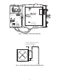
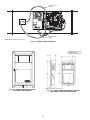
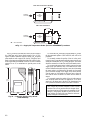
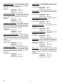
Mount Zone Controller
LOCATION — The zone controller must be mounted on the
air terminal’s damper actuator shaft. For service access, there
should be at least 12 in. of clearance between the front of the
zone controller and adjacent surfaces. Refer to Fig. 6.
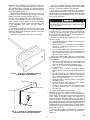
MOUNTING — Perform the following steps to mount the
zone controller:
1. Visually inspect the damper and determine the direc-
tion in which the damper shaft moves to open the
damper — clockwise (CW) or counterclockwise
(CCW). Refer to Fig. 7.
If the damper rotates CCW to open, it does not require
any configuration changes.
If the damper rotates CW to open, then the damper
actuator logic must be reversed. This is done in the
software when performing system start-up and damper
calibration test. Do not attempt to change damper rota-
tion by changing wiring. This will upset the damper
position feedback potentiometer readings.
2. Rotate the damper shaft to the fully closed position.
Note direction of rotation.
3. Press the release button on the actuator and rotate the
clamp in the same direction that was required to close
the damper in Step 2.
4. Press the release button on the actuator and rotate the
actuator back one position graduation. Release the but-
ton and lock the actuator in this position.
5. Mount the zone controller to the terminal by sliding
the damper shaft through the actuator clamp assembly.
Secure the zone controller to the duct by installing
the screw provided through the grommet in the anti-
rotation tab. Be sure the floating grommet is in the
center of the slot. Failure to center the grommet may
cause the actuator to stick or bind.
6. Tighten the actuator clamp assembly to the damper
shaft. Secure by tightening the two 10-mm nuts.
7. If the damper has less than 90 degrees of travel
between the fully open and fully closed positions, then
a mechanical stop must be set on the actuator. The
mechanical stop prevents the damper from opening
past the maximum damper position. To set the
mechanical stop, perform the following procedure:
a. Press the actuator release button and rotate the
damper to the fully open position.
b. Using a Phillips screwdriver, loosen the appropri-
ate stop clamp screw.
c. Move the stop clamp screw so that it contacts the
edge of the cam on the actuator. Secure the stop
clamp screw in this position by tightening the
screw.
8. Verify that the damper opens and closes. Press the
actuator release button and rotate the damper. Verify
that the damper does not rotate past the fully open
position. Release the button and lock the damper in the
fully open position.
HF23BJ042
Made in Switzerland
by Belimo Automation
LR 92800
NEMA 2
Class 2 Supply
LISTED
94D5
TENP IND &
REG. EQUIP.
24VAC/DC
50/60 Hz
3VA 2W
5K
WIP
yel
blu
ora
blk
red wht
COM
1
2
3
35 in-lb (4 Nm)
80...110s
0
1
J4
J3
J1
SRVC
24VAC
+
G
-
HIGH
3art Number: 33ZCFANTRM
S/N:
Bus#:
Element#:
Unit#:
J6
CCW
COM
CW
HEAT1
24VAC
HEAT2
ZONE Controller
®
®
C
US
LOW
1
6
3
1
+
G
-
J2A
CCN
LEN
J2B
+
G
-
1
1
1
3
3
2
15
16
FAN AC
FAN
24VAC
N/A
HEAT3
J7
J6
1
1
2
3
ACTUATOR
CLAMP
ASSEMBLY
DAMPER
SHAFT
LOW PRESSURE
TUBING ROUTING
GROMMET
ANTI-
ROTATION
TAB
HIGH
PRESSURE
TUBING
ROUTING
ACTUATOR
RELEASE
BUTTON
MECHANICAL
STOP
RH/IAQ
GND
SECFLOW
+10V
DMPPOS
GND
TEST
GND
+24V
SPT
GND
SAT
T56
GND
PAT
REMOTE
CW
COM
COW
J8
SEC DMP
1
3
→
Fig. 2 — Zone Controller Physical Details (33ZCFANTRM Shown)
NOTE: Actuator clamp accepts dampers
shafts with the following characteristics:
Round —
1
/
4
-in. to
5
/
8
-in.
(6 to 16 mm)
Square —
1
/
4
-in. to
7
/
16
-in.
(6 to 11 mm)
Damper shaft must be a minimum of 1.5-in.
(38 mm) long.
801

5
—
HF23BJ042
Made in Switzerland
by Belimo Automation
LR 92800
NEMA 2
Class 2 Supply
LISTED
94D5
TENP IND &
REG. EQUIP.
24VAC/DC
50/60 Hz
3VA 2W
5K
WIP
yel
blu
ora
blk
red wht
COM
1
2
3
35 in-lb (4 Nm)
80...110s
0
1
J4
J3
J1
SRVC
24VAC
+
G
-
HIGH
Part Number: 33ZCVAVTRM
S/N:
Bus#:
Element#:
Unit#:
J6
CCW
COM
CW
HEAT1
24VAC
HEAT2
ZONE Controller
®
®
C
US
LOW
1
6
3
1
+
G
-
J2A
CCN
LEN
J2B
+
G
-
1
1
1
3
3
2
15
16
RH/IAQ
GND
SECFLOW
+10V
DMPPOS
GND
TEST
GND
+24V
SPT
GND
SAT
T56
GND
PAT
REMOTE
HF23BJ042
Made in Switzerland
by Belimo Automation
LR 92800
NEMA 2
Class 2 Supply
LISTED
94D5
TENP IND &
REG. EQUIP.
24VAC/DC
50/60 Hz
3VA 2W
5K
WIP
yel
blu
ora
blk
red wht
COM
1
2
3
35 in-lb (4 Nm)
80...110s
0
1
J4
J3
J1
SRVC
24VAC
+
G
-
HIGH
Part Number: 33ZCFANTRM
S/N:
Bus#:
Element#:
Unit#:
J6
CCW
COM
CW
HEAT1
24VAC
HEAT2
ZONE Controller
®
®
C
US
LOW
1
6
3
1
+
G
-
J2A
CCN
LEN
J2B
+
G
-
1
1
1
3
3
2
15
16
FAN AC
FAN
24VAC
N/A
HEAT3
J7
J6
1
1
2
3
RH/IAQ
GND
SECFLOW
+10V
DMPPOS
GND
TEST
GND
+24V
SPT
GND
SAT
T56
GND
PAT
REMOTE
CW
COM
COW
J8
SEC DMP
1
3
→
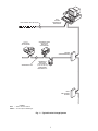
Fig. 3 — VAV Fan Terminal Zone Controller
→
Fig. 4 — Single Duct Air Terminal Zone Controller
801

6
35 in-lb (4 Nm)
80...110s
HF23BJ042
Made in Switzerland
by Belimo Automation
LR 92800
NEMA 2
LISTED
94D5
TEMP. IND. &
REG. EQUIP.
U
L
Class 2 Supply
24VAC/DC
50/60Hz
3VA 2W
COM
1
2
3
blk
red
wht
yel
blu
ora
WIP
5K
®
LOW
HIGH
Unit#:
Part Number: 33ZCSECTRM
S/N:
J1
J2
CCW
COM
CW
N/A
N/A
N/A
GND
OUT
+10V
CW
COM
CCW
1
0
J1
D
FLOW
TPUT
OV
MMON
CW
6
1
1
6
ZONE Controller
®
US
C
Fig. 5 — Secondary Terminal Zone Controller
END VIEW INLET
ZONE
CONTROLLER
ALLOW 12” CLEARANCE FOR SERVICE
ACCESS TO CONTROL BOX
3” REF.
Fig. 6 — Service Clearance for Zone Controller Mounting

7
Connect the Power Transformer —
An individual,
field-supplied, 24 vac power transformer is recommended for
each zone controller. If multiple zone controllers are powered
from one power transformer (100 va maximum for UL [Under-
writers’ Laboratories] Class 2 conformance), maintain polarity
on the power input terminals. All transformer secondaries are
required to be grounded. Use only stranded copper conductors
for all wiring to the zone controller. Wiring connections must
be made in accordance with NEC (National Electrical Code)
and local codes. Ground the transformer at the transformer lo-
cation. Provide an 18-gage, green, chassis ground wire at the
terminal.
The power supply is 24 vac ± 10% at 40 va (50/60 Hz).
For 33ZCVAVTRM zone controllers, the power require-
ment sizing allows for accessory water valves and for electric
heat contactor(s). Water valves are limited to 15 va on both
two-position and modulating hot water. The electric heat con-
tactor(s) are limited to 10 va (holding) each.
For 33ZCFANTRM zone controllers, the power require-
ment sizing allows for accessory water valves and for the fan
contactor. Water valves are limited to 8 va on both two-position
and modulating hot water. The fan contactor is limited to
11 va (holding).
NOTE: If a water valve or electric heat contactor exceeds
these limits, or external contactors are required for electric
heat, then it is recommended a 60 va transformer be used.
The maximum rating for any output is 20 va.
NOTE: Do not run sensor or communication wiring in the
same conduit with line-voltage wiring.
NOTE: An accessory conduit box (part no. 33ZCCONBOX) is
available for conduit wiring connections to the zone controller.
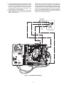
Perform the following steps to connect the power
transformer:
1. Install the field-supplied transformer in an electrical
enclosure that conforms to NEC and local codes.
2. Connect 24 vac from the transformer as shown in the
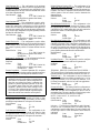
applicable wiring diagram (Fig. 8A-J).
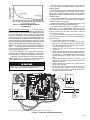
Connect Airflow Pickups —
The zone controller de-
termines velocity pressure by obtaining the difference between
high and low duct pressure from two airflow pickups. The
pickups are connected to barb fittings on the zone controller
with
1
/
4
-in. polyethylene tubing. All piping for this purpose
must conform to local codes.
Figure 9 indicates the positions of the two barb fittings.
Perform the following steps to install and connect the air-
flow pickups:
1. Select a location on the air handler’s supply air duct
where the airflow pickups will be installed. The loca-
tion should be one where there are at least three duct
diameters of straight duct upstream of the pickups. If
this requirement is not met, stable airflow measure-
ments may not be possible.
2. Mount the field-supplied airflow pickup(s) in the duct,
following the manufacturer's directions. Two individ-
ual pickups may be used, one for high pressure airflow
and one for low pressure airflow. A dual pickup, which
combines the two functions, may also be used. When
using individual pickups, make sure that the one for
high pressure airflow faces upstream, in the direction
the air is coming from, and the one for low pressure
airflow faces downstream, in the direction the air is
going to.
3. Use field-supplied
1
/
4
-in. tubing (rated for the applica-
tion) to connect the high pressure airflow pickup to
barb fitting P1 on the pressure transducer. At the zone
controller, the P1 fitting is on the side with the filter
installed. Be careful to avoid sharp bends in the tubing,
because malfunctions may occur if the tubing is bent
too sharply. Use at least 2 ft of tubing for reading
stability.
4. Use field-supplied
1
/
4
-in. tubing (rated for the applica-
tion) to connect the low pressure airflow pickup to
barb fitting P2 on the pressure transducer. Be careful to
avoid sharp bends in the tubing, because malfunctions
may occur if the tubing is bent too sharply. Use at least
2 feet of tubing for stability.
AIR
FLOW
AIR
FLOW
CW TO OPEN, CCW TO CLOSE
CCW TO OPEN, CW TO CLOSE
Fig. 7 — Damper Configuration

8
2W
3VA
50/60Hz
24VAC/DC
HF23BJ042
80...110s
35 in-lb(4Nm)
SAT
SPT
HEAT2HEAT1 24VAC
B
W
R
24 VAC
RBW
Low
Hi
Wht
RedBlk
com
Ora
BluYel
10
N/A
PAT
T56
SAT
SPT
+24V
SECFLOW
DMPPOS
+10V
GND
GND
GND
GND
GND
RH/IAQ
Or
Bl
Y
Voltage
Line
comunications
CCN
Not used
comunications
CCN
Automation
By Belimo
Switzerland
Made in
(+)
(GND)
(-)
TRAN
REMOTE
TRANSFORMER
GROUND
TERMINAL
GROUND
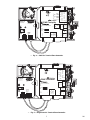
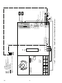
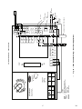
Fig. 8A — Zone Controller Wiring — Single Duct Air Terminal, Cooling Only
LEGEND
CCN —
Carrier Comfort Network
SAT —
Supply-Air Temperature Sensor
SPT —
Space Temperature Sensor
TRAN —
Transformer
Field Wiring
Factory Wiring
→
303

9
HWV
Automation
By Belimo
Switzerland
Made in
2W
3VA
50/60Hz
24VAC/DC
HF23BJ042
80...110s
35 in-lb(4Nm)
SAT
SPT
HEAT2HEAT1 24VAC
N/A
PAT
T56
SAT
SPT
+24V
SECFLOW
DMPPOS
+10V
GND
GND
GND
GND
GND
RH/IAQ
B
W
R
24 VAC
Or
Bl
Y
RBW
Low
Hi
WhtRedBlk
com
Ora
BluYel
10
comunications
CCN
Not used
comunications
CCN
Voltage
Line
TRAN
(+)
(GND)
(-)
REMOTE
TRANSFORMER
GROUND
TERMINAL
GROUND
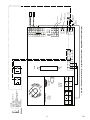
Fig. 8B — Zone Controller Wiring — Single Duct Air Terminal, Two-Position Hot Water Heat
LEGEND
*Normally open or normally closed valve may
be used.
CCN —
Carrier Comfort Network
HWV —
Hot Water Valve
SAT —
Supply-Air Temperature Sensor
SPT —
Space Temperature Sensor
TRAN —
Transformer
Field Wiring
Factory Wiring
→
303

10
CL
OP
COM
HWV
Voltage
Line
Automation
By Belimo
Switzerland
Made in
2W
3VA
50/60Hz
24VAC/DC
HF23BJ042
80...110s
35 in-lb(4Nm)
SAT
SPT
HEAT2HEAT1 24VAC
N/A
PAT
T56
SAT
SPT
+24V
SECFLOW
DMPPOS
+10V
GND
GND
GND
GND
GND
RH/IAQ
B
W
R
24 VAC
Or
Bl
Y
RBW
Low
Hi
WhtRedBlk
com
Ora
BluYel
10
comunications
CCN
Not used
comunications
CCN
(+)
(GND)
(-)
TRAN
REMOTE
TRANSFORMER
GROUND
TERMINAL
GROUND
Fig. 8C — Zone Controller Wiring — Single Duct Air Terminal, Modulating Hot Water Heat
LEGEND
*Required for some spring return modulating
valves.
CCN —
Carrier Comfort Network
HWV —
Hot Water Valve
SAT —
Supply-Air Temperature Sensor
SPT —
Space Temperature Sensor
TRAN —
Transformer
Field Wiring
Factory Wiring
→
303

11
H2 H1
Voltage
Line
Automation
By Belimo
Switzerland
Made in
2W
50/60Hz
24VAC/DC
HF23BJ042
80...110s
35 in-lb(4Nm)
SAT
SPT
HEAT2HEAT1 24VAC
N/A
PAT
T56
SAT
SPT
+24V
SECFLOW
DMPPOS
+10V
GND
GND
GND
GND
GND
RH/IAQ
B
W
R
24 VAC
Or
Bl
Y
RBW
Low
Hi
WhtRedBlk
com
OraBluYel
10
comunications
CCN
comunications
CCN
TRAN
Not Used
3VA
(+)
(GND)
(–)
TRANSFORMER
GROUND
TERMINAL
GROUND
REMOTE
Fig. 8D — Zone Controller Wiring — Single Duct Air Terminal, Staged Electric Heat (2 Stages)
LEGEND
CCN —
Carrier Comfort Network
H —
Heater Relay
HWV —
Hot Water Valve
SAT —
Supply-Air Temperature Sensor
SPT —
Space Temperature Sensor
TRAN —
Transformer
Field Wiring
Factory Wiring
→
801

12
H3 H2 H1
Voltage
Line
2W
3VA
50/60Hz
24VAC/DC
HF23BJ042
80...110s
35 in-lb(4Nm)
SAT
SPT
FAN
HEAT2HEAT1 24VAC
N/A
PAT
T56
SAT
SPT
+24V
SECFLOW
DMPPOS
+10V
GND
GND
GND
GND
GND
RH/IAQ
Damper
Second
CCW
COM
CW
Heat3
Used
Not
24 VAC
B
W
R
B
W
R
24 VAC
Or
Bl
Y
RBW
Low
Hi
WhtRedBlk
com
Ora
BluYel
10
comunications
CCN
Not used
comunications
CCN
Automation
By Belimo
Switzerland
Made in
TRAN
FAN AC
REMOTE
TRANSFORMER
GROUND
TERMINAL
GROUND
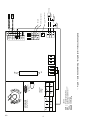
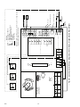
Fig. 8E — Zone Controller Wiring — Single Duct Air Terminals, Staged Electric Heat (3-Stage)
LEGEND
CCN —
Carrier Comfort Network
H —
Heater Relay
SAT —
Supply-Air Temperature Sensor
SPT —
Space Temperature Sensor
TRAN —
Transformer
Field Wiring
Factory Wiring
NOTE: The VAV fan terminal zone controller is used on single duct air
terminals with 3 stages of electric heat.
→
303

13
Fan
Contactor
Fan Motor
Voltage
Line
Voltage
Line
M
By Belimo
2W
3VA
50/60Hz
24VAC/DC
HF23BJ042
80...110s
35 in-lb(4Nm)
SPT
FAN
HEAT2HEAT1 24VAC
N/A
PAT
T56
SAT
SPT
+24V
SECFLOW
DMPPOS
+10V
GND
GND
GND
GND
GND
RH/IAQ
Damper
Second
CCW
COM
CW
Heat3
Used
Not
24 VAC
FAN
AC
B
W
R
24 VAC
Or
Bl
Y
RBW
Low
Hi
WhtRedBlk
com
OraBluYel
10
comunications
CCN
Not Used
comunications
CCN
TRAN
(–)
(+)
(GND)
Automation
Switzerland
Made in
TRANSFORMER
GROUND
TERMINAL
GROUND
REMOTE
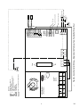
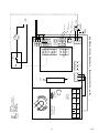
Fig. 8F — Zone Controller Wiring — Fan Powered Terminals, Cooling Only
LEGEND
CCN —
Carrier Comfort Network
SPT —
Space Temperature Sensor
TRAN —
Transformer
Field Wiring
Factory Wiring
→
801

14
HWV
Fan Motor
Voltage
Line
Voltage
Line
M
2W
3VA
50/60Hz
24VAC/DC
HF23BJ042
80...110s
35 in-lb(4Nm)
SAT
SPT
FAN
HEAT2HEAT1 24VAC
N/A
PAT
T56
SAT
SPT
+24V
SECFLOW
DMPPOS
+10V
GND
GND
GND
GND
GND
RH/IAQ
Damper
Second
CCW
COM
CW
Heat3
24 VAC
B
W
R
24 VAC
Or
Bl
Y
RBW
Low
Hi
WhtRedBlk
com
OraBluYel
10
Not Used
Automation
By Belimo
Switzerland
Made in
comunications
CCN
comunications
CCN
(-)
(+)
(GND)
Not Used
TRAN
TRANSFORMER
GROUND
TERMINAL
GROUND
FAN AC
Fan Contactor
REMOTE
Fig. 8G — Zone Controller Wiring — Fan Powered Terminals, Two-Position Hot Water Heat
LEGEND
CCN —
Carrier Comfort Network
HWV —
Hot Water Valve
SAT —
Supply-Air Temperature Sensor
SPT —
Space Temperature Sensor
TRAN —
Transformer
Field Wiring
Factory Wiring
→
801

15
HWV
Fan Motor
Voltage
Line
Voltage
Line
M
2W
3VA
50/60Hz
24VAC/DC
HF23BJ042
80...110s
35 in-lb(4Nm)
SAT
SPT
FAN
HEAT2HEAT1 24VAC
N/A
PAT
T56
SAT
SPT
+24V
SECFLOW
DMPPOS
+10V
GND
GND
GND
GND
GND
RH/IAQ
Damper
Second
CCW
COM
CW
Heat3
Used
Not
24 VAC
B
W
R
24 VAC
Or
Bl
Y
RBW
Low
Hi
WhtRedBlk
com
OraBluYel
10
PAT*
Not Used
comunications
CCN
comunications
CCN
(+)
(GND)
(-)
TRAN
Automation
By Belimo
Switzerland
Made in
TRANSFORMER
GROUND
TERMINAL
GROUND
FAN AC
COM
CL
OP
24V*
Fan Contactor
REMOTE
Fig. 8H — Zone Controller Wiring — Fan Powered Terminals, Modulating Hot Water Heat
LEGEND
CCN —
Carrier Comfort Network
HWV —
Hot Water Valve
PAT —
Primary Air Temperature Sensor
SAT —
Supply-Air Temperature Sensor
SPT —
Space Temperature Sensor
TRAN —
Transformer
Field Wiring
Factory Wiring
*Required only on Linkage master if on a non-compatible air source.
→
801

16
Fan Motor
Voltage
Line
M
H3 H2 H1
Voltage
Line
2W
3VA
50/60Hz
24VAC/DC
HF23BJ042
80...110s
35 in-lb(4Nm)
SAT
SPT
FAN
HEAT2HEAT1 24VAC
N/A
PAT
T56
SAT
SPT
+24V
SECFLOW
DMPPOS
+10V
GND
GND
GND
GND
GND
RH/IAQ
Damper
Second
CCW
COM
CW
Heat3
24 VAC
B
W
R
24 VAC
Or
Bl
Y
RBW
Low
Hi
WhtRedBlk
com
OraBluYel
10
Fan Contactor
REMOTE
comunications
CCN
Not Used
comunications
CCN
PAT*
(+)
(-)
(GND)
TRAN
FAN AC
Not Used
Automation
By Belimo
Switzerland
Made in
TRANSFORMER
GROUND
TERMINAL
GROUND
Fig. 8I — Zone Controller Wiring — Fan Powered Terminals, Staged Electric Heat
*Required only on Linkage master if on a non-compatible air source.
→
LEGEND
CCN — Carrier Comfort Network
H — Heater Relay
PAT — Primary Air Temperature Sensor
SAT — Supply-Air Temperature Sensor
SPT — Space Temperature Sensor
TRAN — Transformer
Field Wiring
Factory Wiring
801

17
FAN AC
Not Used
LINE
VOLTAGE
TRAN
Not Used
(+)
(GND)
(-)
SHIELD
SHIELDED (CCN-TYPE) CABLE
REMOTE
TRANSFORMER
GROUND
TERMINAL
GROUND
comunications
CCN
comunications
CCN
2W
3VA
50/60Hz
24VAC/DC
HF23BJ042
80...110s
35 in-lb(4Nm)
SPT
FAN
HEAT2HEAT1 24VAC
N/A
PAT
T56
SAT
SPT
+24V
SECFLOW
DMPPOS
+10V
GND
GND
GND
GND
GND
RH/IAQ
Damper
Second
CCW
COM
CW
Heat3
24 VAC
B
W
R
24 VAC
Or
Bl
Y
RBW
Low
Hi
WhtRedBlk
com
OraBluYel
10
Automation
By Belimo
Switzerland
Made in
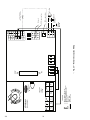
Fig. 8J — Zone Controller Wiring — Dual Duct Applications
LEGEND
CCN —
Carrier Comfort Network
SPT —
Space Temperature Sensor
TRAN —
Transformer
Field Wiring
Factory Wiring
PRIMARY DAMPER — 33ZCFANTRM
→
303

18
2W
3VA
50/60Hz
24VAC/DC
HF23BJ042
80...110s
35 in-lb(4Nm)
GND
CCW
SECFLOW
+10V
CW
GND
Or
Bl
Y
RBW
Low
Hi
WhtRedBlk
com
OraBluYel
10
Automation
By Belimo
Switzerland
Made in
Fig. 8J — Zone Controller Wiring — Dual Duct Applications (cont)
LEGEND
CCN —
Carrier Comfort Network
SPT —
Space Temperature Sensor
TRAN —
Transformer
Field Wiring
Factory Wiring
SECONDARY DAMPER — 33ZCSECTRM

19
Install Sensors
SPACE TEMPERATURE SENSOR INSTALLATION —
A space temperature sensor must be installed for each zone
controller. There are three types of SPT sensors available from
Carrier: the 33ZCT55SPT space temperature sensor with timed
override button, the 33ZCT56SPT space temperature sensor
with timed override button and set point adjustment and the
33ZCT58SPT with liquid crystal display. See Fig. 10.
The space temperature sensor is used to measure the build-
ing interior temperature and should be located on an interior
building wall. The sensor wall plate accommodates the NEMA
standard 2 x 4 junction box. The sensor can be mounted direct-
ly on the wall surface if accpectable by local codes.
Do not mount the sensor in drafty locations such as near air
conditioining or heating ducts, over heat sources such as base-
board heaters, radiators, or directly above wall mounted light-
ing dimmers. Do not mount the sensor near a window which
may be opened, near a wall corner, or a door. Sensors mounted
in these areas will have inaccurate and erratic sensor readings.
The sensor should be mounted approximately 5 ft from the
floor, in an area representing the average temperature in the
space. Allow at least 4 ft between the sensor and any corner
and mount the sensor at least 2 ft from an open doorway.
Install the sensor as follows (see Fig. 11):
1. Locate the two Allen type screws at the bottom of the
sensor.
2. Turn the two screws clockwise to release the cover
from the sensor wall mounting plate.
3. Lift the cover from the bottom and then release it from
the top fasteners.
4. Feed the wires from the electrical box through the
opening in the center of the sensor mounting plate.
5. Using two no. 6-32 x 1 mounting screws (provided
with the sensor), secure the sensor to the electrical box.
6. Use 20 gage wire to connect the sensor to the control-
ler. The wire is suitable for distances of up to 500 ft.
Use a three-conductor shielded cable for the sensor
and set point adjustment connections. The standard
CCN communication cable may be used. If the set
point adjustment (slidebar) is not required, then an
unshielded, 18 or 20 gage, two-conductor, twisted pair
cable may be used.
The CCN network service jack requires a separate,
shielded CCN communication cable. Always use sepa-
rate cables for CCN communication and sensor wir-
ing. (Refer to Fig. 12 for wire terminations.)
7. Replace the cover by inserting the cover at the top of
the mounting plate first, then swing the cover down
over the lower portion. Rotate the two Allen head
screws counterclockwise until the cover is secured to
the mounting plate and locked in position.
8. For more sensor information, see Table 1 for ther-
mistor resistance vs temperature values.
NOTE: Clean sensor with damp cloth only. Do not use
solvents.
Wiring the Space Temperature Sensor
(33ZCT55SPT and
33ZCT56SPT) — To wire the sensor, perform the following
(see Fig. 12 and 13):
1. Identify which cable is for the sensor wiring.
2. Strip back the jacket from the cables for at least
3-inches. Strip
1
/
4
-in. of insulation from each conduc-
tor. Cut the shield and drain wire from the sensor end
of the cable.
3. Connect the sensor cable as follows:
a. Connect one wire from the cable (RED) to the
SPT terminal on the controller. Connect the other
end of the wire to the left terminal on the SEN ter-
minal block of the sensor.
b. Connect another wire from the cable (BLACK) to
the GND terminal on the controller. Connect the
other end of the wire to the remaining open termi-
nal on the SEN terminal block.
c. On 33ZCT56SPT thermostats, connect the re-
maining wire (WHITE/CLR) to the T56 terminal
on the controller. Connect the other end of the
wire to the right most terminal on the SET termi-
nal block.
d. In the control box, install a No. 6 ring type crimp
lug on the shield drain wire. Install this lug under
the mounting screw in the upper right corner of
the controller (just above terminal T1).
e. On 33ZCT56SPT thermostats install a jumper
between the two center terminals (right SEN and
left SET).
Wiring the Space Temperature Sensor (33ZCT58SPT)
— The
T58 space temperature sensor is wired differently than other
conventional sensors. The T58 sends all its sensor information
through the CCN bus to the zone controller that is is associated
with. The SPT sensor wiring connections are not used. The T58
sensor does not need to be directly wired to the zone controller.
The T58 sensor may be powered by a separate 24-VAC pow-
er supply or may be connected to the J1 24 VAC power termi-
nals on the zone controller. Be sure that the polarity of the power
supply connections are consistent. For multiple devices wired to
the same power supply, all positive (+) and negative (–) termi-
nals should be wired in the same polarity.
Wire the T58 sensor to the CCN. Connect the CCN + termi-
nal to the RED signal wire (CCN+). Connect the CCN – termi-
nal to the BLACK signal wire (CCN–). Connect the GND
terminal to the WHITE/CLEAR signal wire (Ground). Refer to
the T58 sensor Installation Instructions for more information
on installing and wiring the sensor.
Wiring the CCN Network Communication Service Jack
—
See Fig. 12, 13, and 14. To wire the service jack, perform the
following:
1. Strip back the jacket from the CCN communication
cable(s) for at least 3 inches. Strip
1
/
4
-in. of insulation
from each conductor. Remove the shield and separate
the drain wire from the cable. Twist together all the
shield drain wires and fasten them together using an
closed end crimp lug or a wire nut. Tape off any
exposed bare wire to prevent shorting.
2. Connect the CCN + signal wire(s) (RED) to
Terminal 5.
3. Connect the CCN – signal wire(s) (BLACK) to
Terminal 2.
4. Connect the CCN GND signal wire(s) (WHITE/CLR)
to Terminal 4.
IMPORTANT: The T58 sensor must be configured with
the bus address and device type of the zone controller
before it will broadcast temperature to the zone control-
ler. Refer to the T58 sensor Installation Instructions for
more information on configuring the sensor.
→
→
801

20
35 in-lb (4 Nm)
80...110s
HF23BJ042
Made in Switzerland
by Belimo Automation
1
0
yel
blu
ora
WIP
5K
LISTED
94D5
TEMP. IND. &
REG. EQUIP.
U
L
Class 2 Supply
LR 92800
NEMA 2
24VAC/DC
50/60Hz
3VA 2W
COM
1
2
3
blk
red
wht
H
L
LOW PRESSURE
TUBING
HIGH PRESSURE
TUBING
Warm
Cool
NOTE: Minimum length of tubing is 2 ft.
Fig. 9 — Airflow Pickup Installation
Fig. 10 — Space Temperature Sensor
(P/N 33ZCT56SPT Shown)
NOTE: Dimensions are in inches.
Fig. 11 — Space Temperature Sensor and Wall
Mounted Humidity Sensor Mounting
Page is loading ...
Page is loading ...
Page is loading ...
Page is loading ...
Page is loading ...
Page is loading ...
Page is loading ...
Page is loading ...
Page is loading ...
Page is loading ...
Page is loading ...
Page is loading ...
Page is loading ...
Page is loading ...
Page is loading ...
Page is loading ...
Page is loading ...
Page is loading ...
Page is loading ...
Page is loading ...
Page is loading ...
Page is loading ...
Page is loading ...
Page is loading ...
Page is loading ...
Page is loading ...
Page is loading ...
Page is loading ...
Page is loading ...
Page is loading ...
Page is loading ...
Page is loading ...
-
 1
1
-
 2
2
-
 3
3
-
 4
4
-
 5
5
-
 6
6
-
 7
7
-
 8
8
-
 9
9
-
 10
10
-
 11
11
-
 12
12
-
 13
13
-
 14
14
-
 15
15
-
 16
16
-
 17
17
-
 18
18
-
 19
19
-
 20
20
-
 21
21
-
 22
22
-
 23
23
-
 24
24
-
 25
25
-
 26
26
-
 27
27
-
 28
28
-
 29
29
-
 30
30
-
 31
31
-
 32
32
-
 33
33
-
 34
34
-
 35
35
-
 36
36
-
 37
37
-
 38
38
-
 39
39
-
 40
40
-
 41
41
-
 42
42
-
 43
43
-
 44
44
-
 45
45
-
 46
46
-
 47
47
-
 48
48
-
 49
49
-
 50
50
-
 51
51
-
 52
52


Carrier 33ZCFANTRM User manual
- Category
- Thermostats
- Type
- User manual
- This manual is also suitable for
Ask a question and I''ll find the answer in the document
Finding information in a document is now easier with AI
Related papers
-
Carrier 33ZCFANCOL Installation, Start-Up And Configuration Instructions
-
-
-
-
-
-
-
-
-
Other documents
-
FläktGroup LQAZ-28 Damper Installation guide
-
Aprilaire 8028 User manual
-
Broan PCSPC800 Installation guide
-
3M Detection Solutions DL DPR Operating instructions
-
Johnson Controls LN series Installation Instructions Manual
-
LG PBZC80.ENCXLEU Installation guide
-
 temperzone SAT-3 Quick start guide
-
Verano VER-24 User manual
-
Trane BAYSENS250A Specification
-
