Page is loading ...


2
1. Ordering key .........................................................................….…………….………….…….
2. Description of infrared heater HELIOS-S ......................................................................……
3
3. Description of function.......................................................................................................….
4
4. Versions…...................................................................................................................….…..
4
5. Dimensions and weights...............................................................................................….….
4
6. Scheme of infrared heaters....….…....................................................................................….
5
7. Pressure losses.................................................................................................................….
7
8. Examples of flue gas exhaust and combustion air supply solutions...............................….….
8
9. Technical parameters..................................................................................................….…..
10
10. Mounting components of infrared heater HELIOS-S.....................................................….…
11
11. Mounting of infrared heater body....................................................................................….
12
12. Installation of burner box………………......................................................................….…..
15
13. Installation of the exhaust box...................................................................................….…..
15
14. Gas connection installation......................................................................................….……
16
15. Electrical installation....................................................................................….…….……….
16
16. Adjustment procedure, adjustment values.......................................................................….
17
17. Operating Instructions..........................................................................................................
19
18. Maintenance........................................................................................................................
19
19. Failure of infrared heaters HELIOS-S and their removal.................................................….
20
20. Conversion to another type of fuel....................................................................................….
22
21. Components used in infrared heaters HELIOS-S..............................................................…
22
22. Control box.........................................................................................................….………..
23
23. Wiring diagram..........................................................................................….……….………
25
24. Economizer functional description........................................................................................
26
25. Pressure loses on flue gas side......................................................................................….
26
26. Dimensions of economizer.....................................................................................….……..
26
27. Technical data and wiring diagram of economizer.....................................................….…..
27
28. Installation of economizer............................................................................................….…
27

3
Dark tube infrared heater HELIOS-SI (single-stage) and HELIOS-SID (two-stage) is a modern
ecological gas heater. It can be supplemented with an economizer to utilize the residual heat of the flue
gas.
In terms of operating temperature of active surfaces and thus in terms of the particular wavelength of
the emitted radiation, the device belongs to the category of so-called "dark" infrared heaters. The active
surface is formed by radiant pipes and a reflector. In the radiant pipes there is the process of fuel gas
burning and there are also burnt gases flowing through the pipes to the mouth of the exhaust fan. Fuel
burning is carried out by an atmospheric burner which is automatically controlled. The reflector prevents
the pipes from cooling by the process of convection. The reflector itself warms up by the radiant pipes
and radiates the heat in the required direction.
Normal operating fuel of the HELIOS infrared heaters:
●natural gas – NG (G20/G25)
Product category:
●II2E3B/P, II2ELL3B/P, design A2, B22, C12, C32, C62. Třída NOX 3 (acc. EN 416-1/A1).
Infrared heaters HELIOS are intended for environment protected against weather impacts with the
classification of climatic conditions class 3K5 acc. EN 60721-3-3 with temperature range from 0° to
35°C, for BNV premises acc. EN 1127-1. Installing infrared heaters as design C is possible, except of
normal spaces also in areas intended for decommissioning and maintenance of vehicles. Such
installation must be assessed by the competent authorities in accordance with the applicable regulations.
Infrared heaters cannot be installed in individual, row and collective garages, motor vehicle garages and
operating rooms of fuel filling stations with fuel dispensers. Infrared heaters cannot also be installed in
places where there is a risk of fire or explosion or high levels of flammable dust.
Infrared heaters are suspended under the ceiling or on the walls in the upper areas of the buildings so
that the radiated beams point to the floor towards the heated residential zone. The surfaces of floors,
walls, machines and other objects are heated by radiation and the surrounding air is heated from them.
The infrared heater HELIOS consists of the following main parts:
●
● with hinges and the radiant heating tubes "U" or "I"
The basic design of the burner box is scalded by the throat for the external suction in the upper part of
the burner box. If the combustion air supply system is not connected, it is an open gas appliance. Thus,
infrared heaters can only be used in a basic (normal) environment according to the according to the
relevant standard. In order to be considered as a closed gas appliance, the radiator must be connected
to outdoor air intake system.
NG
-
Natural gas (G20/G25)
+
-
isolated
D
-
Two-stage
-
Single-stage (On / Off)
U
I
33S, 50S, 70S, 100S

4
● Infrared heater operation is controlled by the located in the burner box.
● After connecting to the el. network, first the basic test of the connected devices to the automatic is
performed and if everything is OK, the exhaust fan is activated.
● After the fan starts and a vacuum is evoked in the burner chamber, the differential air manostat is
switched. The manostat senses the pressure differential caused by the exhaust fan.
● When the manostat is switched on, the venting time (approx. 50 s) starts to run, this is used to
ventilate the flue gas exhaust pipe and heating tubes.
● After this ventilation time, the electromagnetic double valve is opened and gas is injected into the
burner. At the same time, the ignition system is put into operation by the automatic system.
● The ignition of the gas mixture in the burner is detected by the ionisation electrode.
● If the gas mixture in the burner is not ignited within 5 seconds, the valve closes the gas supply and
the unburned gas / air mixture is vented through the exhaust fan during the next ventilation time. After
it has elapsed, the automation runs two more ignition cycles.
● If no flame is detected during the third ignition cycle, the automatic switches into the fault mode and
the red indicator “Burner Failure” light on.
● Further start is possible after unlocking the fault condition by disconnecting and reconnecting to the
power supply.
● After putting the burner into operation and igniting the gas mixture, the green indicator "Power
supply" and orange indicator "Burner Operation" lights up.
The atmospheric burner control is single-stage or two-stage.
Infrared heater with single-stage burner works in on-off mode, two-stage burner of the infrared heater
operates in off mode - reduced power - full power.
The main advantages of the two-stage burner control include reducing burner start-up frequency, better
temperature distribution in the heated space and reduced energy consumption.
Reflectors are supplied with insulation (thermal insulation, covered by a cover made of galvanized sheet
metal).
244,0 392,5 392,5 547,5 304,7
10,8 14,8 14,8 21,5 20,2

5
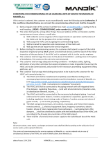
Key:
1 Hinge 100 type 1
2 Hinge 100 type 2
3 Hinge SI+
A Stainless steel tube 4050 mm
B Black tube 3000 mm
C
Black tube 1300 mm
D
Stainless steel tube 4800 mm
E
Black tube 1950 mm
F
Black tube 2505 mm
J
Black tube 2400 mm
H
Stainless steel arch
HELIOS 100 S+
HELIOS 50 SU+
HELIOS 33 SU+
HELIOS 70 SI+
Burner box
Exhaust box
Pipe coupling
H
C
B
B
D
B
F
B
B
B
7 x 2003
14748 mm
1
1
1
2
1
1
1
1
1
B
H
C
C
B
B
A
B
E
B
B
1
1
1
2
1
1
1
7 x 2003
14748 mm
H
E
B
B
B
A
B
5 x 2003
10747 mm
1
2
1
1
1
1
HELIOS 70 SU+
B
B
20174 mm
3
3
3
3
3
3
3
3
3
3
3
J
B
B
D
10 x 1800
B
B
21425 mm
1
1
1
2
1
1
1
1
1
C
B
B
A
1
C
B
B
B
B
B
1
B
A
10 x 2003

6
Suspension methods:
1. Dark tube infrared heaters can be suspended on suitable structure by means of chains or strings and
snap-hooks or tie rods.
2. According to the picture 4 it is necessary to fix the infrared heater at least on two places by using an
appropriate way so that the device cannot be turned around.
3. Due to the thermal expansion, the infrared heater can not be fixed directly to the supporting structure.
4. It is necessary to keep safe distance from flammable objects and walls (Fig. 5, 6).
When installing the heater over the runway of bridge crane, it is necessary to use the protection of
electrical power installation of the crane against excessive heat.

7
DN 125 DN 125 DN 130 DN 130
- DN 125 DN 130 DN 130
- DN 125 DN 150 DN 130
- DN 125 - DN 130
- DN 125 DN 130 DN 130
Min. 300 mm Min. 300 mm
1,0 1,5 3 3,5 7 16 18 4,5 5,5 6,5 3 5
1 1 2 2 4 9 12 3 4 4 2 2
2 3 6 6 12 27 32 7 9 12 9 6
1 2,0 3,5 5,0 5,0 17 19 4,0 5,0 6,0 3,5 3,5
3,5 4,5 7 9 14 33 - 10 12 14 7 9
2,5 3,5 5 6,0 10 25 28 7 9 10 5 6
2 3 6 6 12 27 32 7 9 12 9 6
1 2 3,5 5 5 17 19 4 5 6 3,5 3,5
For pressure losses of individual flue system components see following tables.
Total pressure loss of flue system can be calculated as sum of pressure losses of all components used.
The flue gas duct must be in accordance with applicable standards and regulations.
Minimum internal diameter of the pipeline is 125 mm.
Connecting of the combustion gases to the ventilator must be demountable.
The duct system must prevent the condensate from penetration into the exhaust pipeline.
The duct system must be terminated freely in the exposed position so that the flue gases cannot
face any resistance, and also that combustion cannot return back to the building through windows.
The material of flue gases exhaust must be resistant to corrosion and against flue gases tempera-
ture according to relevant standards.
Opening for flue gases measurement is placed according to heater configuration, for heaters without
economizer the opening is in the first part of the duct immediately after the heater, for heaters with
economizer, the opening is in the first part of the flue duct immediately after the economizer.

8
DN 125 2 3,5 5 6,0 10 20 21 8 9 5
DN 125 4 6 9 10 16 - - 15 16 9
DN 125 4,5 6 9 12 18 - - 13 15,5 9
DN 125 4 6 9 10 16 - - 15 16 9
1 HELIOS heater
2 Condensate trap
3 Tube with throat
4 Bend
5
Join female-female
6
Exhaust head horizontal
7
Air intake head
1
2
3
4
3
6
7354
2%
1 HELIOS heater
2 Condensate trap
3 Tube with throat
4 Flexible duct Al
5 Coaxial chimney
vertical
1
4
3
5
2

9
1 HELIOS heater
2 Condensate trap
3 Tube with throat
4 Exhaust head vertical
5
Air intake head
1
3
3
5
2
3
4
Min. 1000 mm
Min. 2000 mm
Min. 500 mm
The flue gas exhaust is forced by the flue
gas duct inside the building. The appliance
is classified according to the flue into
design version A . The design and installa-
tion of the flue gas exhaust must comply
according the correct norm.
When installing the heater in design A in
enclosed space, it is necessary to ensure
forced ventilation with min. 10 m / h for
each installed kW power consumption of
the heater in design A and it is necessary
to ensure that the device will stop in the
case of non-functional ventilation.
If inclined heaters are installed, rotate the
exhaust cabinet so that the flue gas is
directed vertically upwards.
3
2
2
2

10
2 x 49,5 75,2 75,2 49,5 36,0
2 x 46,0 60,1 60,1 46,0 33,5
2 x 43,5 66,2 66,2 43,5 31,7
2 x 43,0 52,9 52,9 43,0 29,5
2 x 44,6 67,8 67,7 44,6 32,4
2 x 41,4 54,3 54,2 41,4 30,2
2 x 38,3 58,3 58,3 38,4 29,5
2 x 36,4 46,6 46,6 36,4 27,9
230/50
200 250 250 100 100
4
17 - 26
10,36 7,81 7,81 5,18 3,75
10,70 7,81 7,81 5,35 3,89
9,04 6,87 6,87 4,52 3,30
9,42 6,87 6,87 4,71 3,42
6,4 7,4 7,4 6,4 5,0
9,0 9,0 9 9 11,5
12 9 9 12 14,0
7,5 7,5 7,5 7,5 9,0
8,5 7,5 7,5 8,5 10,0
21,5 14,8 20,2 14,8 10,8
547,5 392,5 304,7 392,5 244,0
2x G 3/4"
G 3/4" G 3/4" G 3/4" G 3/4"
2 x DN130
DN 130 DN 130 DN 130 DN 130
350 m3.h-1 650 m3.h-1
650 m3.h-1
350 m3.h-1
350 m3.h-1
360 Pa 610 Pa 610 Pa 360 Pa 360 Pa

11
2 x 49,5 75,2 75,2 49,5 36,0
2 x 46,0 60,1 60,1 46,0 33,5
2 x 44,6 67,8 67,7 44,6 32,4
2 x 41,4 54,3 54,2 41,4 30,2
230/50
200 250 250 100 100
4
17 - 26
10,36 7,81 7,81 5,18 3,75
10,70 7,81 7,81 5,35 3,89
6,4 7,4 7,4 6,4 5,0
9,0 9,0 9 9 11,5
12 9 9 12 14,0
21,5 14,8 20,2 14,8 10,8
547,5 392,5 304,7 392,5 244,0
2x G 3/4"
G 3/4" G 3/4" G 3/4" G 3/4"
2 x DN130
DN 130 DN 130 DN 130 DN 130
350 m3.h-1 650 m3.h-1
650 m3.h-1
350 m3.h-1
350 m3.h-1
360 Pa 610 Pa 610 Pa 360 Pa 360 Pa
Before starting installation, make sure that local condition regarding gas line, fuel and its pressure and
heater setting are compatible.
Installation of the heater must be carried out in such way so that an adequate space for servicing and
adjustment is maintained (Fig. 9, 10). There must be ensured sufficient air exchange in the building to
allow for good combustion of gas. The amount of combustion air for the infrared heaters must meet
applicable standards. For installation of heaters in dusty environment, installation of duct supplying the
combustion air from outside (Closed appliance) is strongly recommended. The installation must comply
with applicable standards and regulations and with this installation manual.
Infrared heaters cannot be installed in places where there is a risk of fire or explosion or high levels of
flammable dust.
Infrared heaters HELIOS-S can be used for heating in public areas where this type of heating is
permitted by legislation. It is necessary to comply with the regulations for installation in these areas.
●Burner box
●Exhaust (ventilation) box
●Connecting cable with connector
●Radiant pipes
●Pipe connections, arch
●Hinges with fixing straps
●Reflectors
●Connecting material

12
Part “1” couplings
with thorns
Thorns of coupling
Pipe
Nut
Washer
Part “2”
couplings
Insert
couplings
Pipe
Screw
Washer
1. Lay out the pipes according to the diagram (Fig. 3).
Use the stainless steel (INOX) pipe as the first piece of heater (from the burner box).
2. Hang the hinges to the appropriate height at the exact spacing of 2003 mm (respectively 1800 mm)
see Fig. 3. The distance between hinges is given by the holes in the reflectors, which are mounted
on the hinge projections and therefore must be respected. Ensure that all fasteners and suspension
elements have sufficient load-bearing capacity. All hinges must have the same orientation so that
the cable protector between the burner and exhaust boxes can be subsequently mounted.
3. Assemble the heating pipes on the hinges according to the diagram in fig. 3. Connect the heating
tubes with the couplings and the coupling insert (fig. 11). Connect the tubes with the coupling insert,
align the holes in the tubes together and fit the coupling parts. Secure the connection with screws.
The coupling locking pins must fit exactly into the holes in the heating tubes. Pull the coupling bracket
firmly - the connection must be rigid and tight.
4. After connecting the heating pipes, fit two rollers into all hinges except the middle one. The Helios
70 SI heater hinges are not fitted with rollers, but the heater is fastened to the hinges with a calliper.
5. Align the heating pipes on the hinges so that the end of the stainless steel pipe overhangs the first
hinge by 150 mm - see Fig. 12.
6. Attach the two heating pipes to the middle hanger, without rollers, and tighten the callipers. The
callipers serve to secure the heating pipes against rotation.
7. Place expansion inserts and reflectors on the hinges. Expansion inserts cannot be placed on the
Helios SI heater hinges.
●Remote control box, connecting cables
●Accessories, auxiliary fastening and connecting material
●Venting or combustion air inlet pipeline
15 cm
Stainless
steel tube
Hinge with
rollers

13
1 Hanging point
2
Expansion insert
3 Strap
4 Washer 6.4
5 Nut M6
6 Protector holder
6
1
2
1
4
5
3
3
Hinge 100 S+ type 2 1×
Expansion insert 1×
Strap 2×
Washer 6.4 4×
Nut M6 4×
1 Hanging point
2
Expansion insert
7 Roller
8 Roller bed
Hinge SU+ type 1 1×
Expansion insert 1×
Roller 2×
1
2
7
7
8
8
1 Hanging point
2 Expansion insert
6 Protector holder
7 Roller
8 Roller bed
Hinge 100 S+ type 1 1×
Expansion insert 1×
Roller 2×
6
1
2
8
7
7
8

14
8. Attach the cable protection holders (1x M8x16 screw, fan washer, nuts) to all Helios 100 and Helios
70I hinges. The Helios SU hinges are not fitted with a protection bracket.
9. Place armor tube (patch cable holder) into Helios 100 S, (SD) radiator guard holders
10. The Helios 100 S +
infrared heater contains 2x3 spinners - 3 in front of each exhaust box. Helios 70 S + and Helios 50
S + contain 3 spinners, Helios 33 S + contains 2 spinners.
Connect the spinners with wire eye before inserting them into the tube. After threading the eye
through the spinners holes, bend the open end of the eye. Bend the last spinners by 90° before
inserting it in the tube so he could not move in it spontaneously.
11. Place the burner and exhaust box on the hanging body (Fig. 20, 21).
Exhaust box
Spinner Tube 127x2 black
1 Hanging point
2
Expansion insert
3 Strap
4 Washer 6.4
5 Nut M6
Hinge SU+ type 2 1×
Expansion insert 1×
Strap 2×
Washer 6.4 4×
Nut M6 4×
1
2
1
3
3
4
5
1 Hanging point
3 Strap
4 Washer 6.4
5 Nut M6
6
Protector holder
Hinge SI+ 1×
Roller 1×
Washer 6.4 2×
Nut M6 2×
6
1
1
3
4
5

15
Pull the socket of burner box over the radiant pipe. By default, the burner box shall be fitted onto the
tube in vertical position, i.e. with the neck for air intake located on the top. If the burner cabinet cannot
be in this position and needs to be turned, it is necessary to consult MANDÍK, a.s. Secure the burner
cabinet after mounting by hanging it by the eye in the back of the cabinet so that the housing neck and
the radiant tube are coaxial. Put the GBS clamp over the socket like when connecting radiant pipes and
tighten it firmly. The recommended torque is 25 Nm. Connect the burner and the exhaust box with the
supplied cable, which, in the I version, is guided by an armored tube placed in the hinges.
stainless steel
tube 127x2
GBS Clamp
Pull the socket of burner box over the
pipe to stop and lock it with GBS clamp
GBS Clamp
Burner box
In the same way as the burner box, the exhaust box is installed and secured too. It can be angled with
the output neck facing the side or top freely. However, it cannot be angled down.
Push to the pipe socket to stop and
lock with clamp and with tenon
Exhaust box
GBS Clamp
Tube 127x2
black

16
Installation of gas connection must be carried out according to applicable standards and regulations
(see. Chap. XI). Pipeline must be ended by a gas ball valve near the joining point of the infrared heater
– max. 1.5 m (Fig. 22). When the infrared heater is in operation, there must be stable and unwavering
gas pressure guaranteed in the pipeline - NG, P, see tab. 9.1 and 9.2. For the connection itself, flexible
gas hose is used. Since the hose withstands the temperatures up to 100 °C, it is necessary to avoid any
contact of the hose with the heater outside the points of connection. The gas lines must be prepared so
as to avoid any contact with direct flame and radiant heat.
Connecting the infrared heater can be carried out only by an authorized person. The gas hose is subject
to periodic revisions as the gas distributions. It is necessary to protect the hoses from mechanical
stresses and aggressive media. The hoses must not be subjected to any tension.
Burner box
Gas hose
Gas connection Ball valve
Place the box of remote control according to the project so that it is freely accessible for the servicing
staff. Connection of the box for remote control to the main supply distribution of 230V/50Hz must be
carried out firmly using suitable three-wire cable. Connection of the box of remote control to the heater
must be carried out firmly by the five-wire cable or seven-wire cable if all signals are to be transferred.
Then connect the cable to the terminal piece according to the relevant wiring diagram (Fig. 26-28).
Installation of electrical connections must be made by an authorized person according to applicable
standards and regulations. The installation must include test of functionality and electric revision.
Connector joining
BURNER BOX - CONTROL BOX
(connector X1-X1')
Connector joining
BURNER BOX - EXHAUST BOX
(connector X2-X2')

17
●Infrared heaters HELIOS-S and their accessories may be put into operation only by a person who is
trained and authorized by MANDÍK, a.s.
●Infrared heaters and their accessories have to be assembled according to this Instruction Manual.
●Safety and fire regulations must be observed according to applicable standards.
●Before putting into operation, it is necessary to submit a copy of the wiring and gas pipelines revision
documents.
●Opening for flue gases measurement: Heaters without economizer have to have opening for flue
gases measurement in the first part of flue duct after the heater, heaters with economizer the
opening for flue gases measurement have to be immediately after the economizer.
●Infrared heaters and their accessories may only be connected to the mains voltage of 230V/50Hz.
●There must be granted access to junction box in which the heaters are connected.
●Main guard valve of gas must be opened, the gas distribution must be vented and adequate gas
overpressure must be assured.
●We recommend presence of a person acting on behalf of assembling company and on behalf of a
user for the purpose of training the operation staff.
1. Check the conformity of assembly of heater, flue gases exhaust and Air-intake duct visually with this
manual.
2. Switch the heater on at nominal power (see chapter 17) and after it starts to work, measure the
pressure on the jet at nominal power. Check the measured value with the table for the respective
heater type bellow and adjust it if necessary.
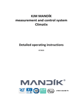
A Gas valve SIT 843 SIGMA
B Control automatics SIT 579 DBC
C Dual cable – two stage heaters only
1 Conical throat for manometer hose insertion
2 Closing screw for jet pressure measuring (flathead screwdriver 4 mm)
3 Setting screw for jet pressure of 2-nd stage (maximum power) with hexagonal head 10 mm
4 Setting screw for jet pressure of 1-st stage (minimum power) for cross-point screwdriver
C
1
2
3
4
A
B

18
1. The heater has to work, switched to maximum power on the control box
2. Loose the screw 2 by two turns
3. Insert the manometer hose (inside diameter of 9 mm) onto conical throat
4. Measure the jet pressure at maximum power
5. With two-stage heater disconnect the dual cable C - this switches the heater to minimum power
6. With two-stage heater measure the jet pressure at minimum power
7. With two-stage heater connect back the dual cable C
8. Remove the manometer hose from conical throat, tighten the screw 2 and perform the gas leakage
test with foaming solution or gas detector
1. Start the jet pressure measuring according to the description above
2. Jet pressure at maximum power can be adjusted by turning the brass setting screw 3 with hexagonal
head using 10 mm wrench - see fig. 24.
3. Jet pressure at minimum power can be adjusted by turning the black screw 4 using cross-point
screwdriver while the brass screw 3 has to be held by 10 mm wrench in order to prevent its
movement. For the direction of screw turning in order to rise or decrease jet pressure, see fig. 24.
4. Switch the heater to minimum power by removing the dual cable (marked with the letter C in figure
24) and check the jet pressure, if necessary, for minimum power according to the table for the type
of radiator and the procedure above.
5. Switch the heater to rated power by connecting a dual cable and recheck the jet pressure at rated
power as described above. The direction of rotation of the screws to increase and decrease the
pressure on the nozzle, see Fig. 24.
6. After adjusting the pressures on the jet, let the heater work at nominal power for further 30-60
minutes to heat it up to working temperature. Then adjust the O2 content in flue gases to values
With one-stage heaters, only the pressure on the jet at nominal power is adjusted. After setting the
pressures on the jet and oxygen content according to the above procedure, other values shall be within limits
according to the respective table of setting values. If differences are observed, check and repair the pipe
connections and connection of burner box and exhaust box.
Zemní plyn Zemní plyn Zemní plyn Zemní plyn Zemní plyn
6,4 7,4 7,4 6,4 5,0
G20: 9,0 G20: 9,0 G20: 9,0 G20: 9,0 G20: 11,5
G25: 12,0 G25: 9,0 G25: 9,0 G25: 12,0 G25: 14,0
G20: 2 x 49,5 G20: 75,2 G20: 75,2 G20: 49,5 G20: 36,0
G25: 2 x 46,0 G25: 60,1 G25: 60,1 G25: 46,0 G25: 33,5
190 - 200 180 - 190 210 - 230 170 - 185 170 - 185
7,0 7,0 7,0 7,0 7,0
0 - 10 0 - 10 0 - 10 0 - 10 0 - 10
150 - 190 150 - 190 150 - 190 150 - 190 150 - 190
7,5 7,5 7,5 7,5 7,5
90 - 91 90 - 91 88 - 89 90 - 92 90 - 92
G20: 7,5 G20: 7,5 G20: 7,5 G20: 7,5 G20: 9,0
G25: 8,5 G25: 7,5 G25: 7,5 G25: 8,5 G25: 10,0
G20: 2 x 43,5 G20: 66,2 G20: 47,9 G20: 43,6 G20: 31,7
G25: 2 x 43,0 G25: 52,9 G25: 52,9 G25: 43,0 G25: 29,5

19
1. Turn the switch „ - STOP - “to the position „STOP“.
2. In case of the long-term breakdown it is suitable to close the gas closing valve in front of the heater.
1. Turn the main electric switch „ “ to the position „1“.
2. Turn the switch „ - STOP - “ to the position „ “ or „ “ (in this case the infra heater operation
is performed under the automatic mode which it is necessary to program according to the relevant
control box instructions). The green indicator of the electric supply „ “ lights up on the control box,
also green indicator on the bottom of burner box will light on.
3. After finishing the ventilation time (app. 50 s), the infrared heater will start and the green light " " on
control box and orange indicator on the bottom of burner box will light on.
4. In case the burner is not fired (the orange lamp of operation on the control box is not alight), the cycle
is repeated twice. If it does not ignite even the third time, the red indicator light on the burner box lights
up to indicate an error. For unblocking the error state, the power supply of the heater must be
disconnected and reconnected (switch " - STOP- " to "STOP" and then back to " " or " " .
If even after several ignition cycles the infra heater is not started, call the service organisation.
5. The output of the two-stage infrared heaters controlled by the can be changed by the " " switch.
"OID" control box controls the power level of the two-stage heaters automatically.
Installation, repairs and conversions may be done by qualified and authorised person only.
●Visual check of the installation in regard of observation all applicable safety standards and regu-
lations.
●Visual check of the appliance and accessories including the flue line.
●Heating tubes and exhaust system permeability, their intactness and tightness.
●Leakage test of gas connection from ball valve to burner incl. gas valve (foaming solution, gas
detector).
●Inspection, eventually cleaning of the burner.
●Inspection, eventually cleaning of the vacuum sensor.
●Measuring the ventilation time of the appliance.
●Exchange of the vacuum hose.
●Manostat function check.
●Inspection of ionisation and ignition electrodes, cleaning, and adjustment if necessary.
●Performance check of the heater.
●Measurement of jet pressures, eventually adjustment.
●Flue gases measurement, eventually adjustment of parameters.
●Safety elements of the appliance.
●Solidity check of all electric connections.
●Check of burner control functioning.
●Check of signalization and switching functionality of control box.
●Visual inspection of all electric insulations of the appliance, their exchange if needed.

20
After each conversion, the appliance must be put back into operation by a service technician trained and
authorized by MANDÍK, a.s. Repairs and reconstructions may only be carried out by a person author-
ized and trained by MANDÍK a.s., who has valid gas and electrical certificates.
- ventilator does
not work (no reaction to the release)
Defective ventilator Replace the ventilator
Defective automatics Replace the automatics
Faulty electric connection of the burner
box
Check the connection – exhaust box
Defective air manostat Replace the air manostat
Defect in the burner box electric connec-
tion
Check the connection (cables)
No connection to the electric supply Check the connection
Defective gas manostat Replace the gas manostat
Low gas pressure in the distribution lines Increase the pressure
- Flue gas exhaustion clogged Clean
Defective air manostat Replace the air manostat
Defective manostat hose – break or
locked
Replace or clean
Defective automatics Replace the automatics
Defect of the burner box electric installa-
tion
(cables)
Check the connection
- ventilator works only during the
aeration and starting (approx. 50s)
Defective electrodes or their setting
or defective electrode cables
Check, replace
Defective covering (orifice opening) Check, set
Defective jet pressure setting Set
Defective gas armature regulator Replace the armature
Defective automatics Replace
Low gas pipeline pressure Increase the pressure
/