Page is loading ...

ENGLISH
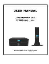
EATON 9130 UPS
5000 - 6000 VA
User's guide
Copyright © 2010 EATON
All rights reserved.
Service and support:
Call your local service representative
9130 UPS-EN

Page 2
9130 UPS-EN
Class A EMC Statements
Requesting a Declaration of Conformity
Units that are labeled with a CE mark comply with the following harmonized standards and EU
directives:
Harmonized Standards: IEC 61000-3-12 l
EU Directives: 2006/95/EC, Council Directive on equipment designed for use within certain l
voltage limits
2004/108/EC, Council Directive relating to electromagnetic compatibility
The EC Declaration of Conformity is available upon request for products with a CE mark.
For copies of the EC Declaration of Conformity, contact Eaton Power Quality or check Eaton website:
www.powerquality.eaton.com
Special Symbols
The following are examples of symbols used on the UPS or accessories to alert you to important
information:
RISK OF ELECTRIC SHOCK - Observe the warning associated with the risk of electric shock symbol.
CAUTION: REFER TO OPERATOR’S MANUAL - Refer to your operator’s manual for additional
information, such as important operating and maintenance instructions.
Do not discard the UPS or the UPS batteries in the trash.
This product contains sealed lead acid batteries and must be disposed as it's explain in this manual.
For more information, contact your local recycling/reuse or hazardous waste center.
This symbol indicates that you should not discard waste electrical or electronic equipment (WEEE) in
the trash. For proper disposal, contact your local recycling/reuse or hazardous waste center.
Information, advice, help.
Directives references
This UPS is classified in the C2 category according to:
EMC: IEC 62040-2 Ed2: 2005
Safety: IEC 62040-1: 2008 (IEC 60950-1)
Performance: IEC 62040-3: 1999
For immunity and safety tests, see Table 22 p. 33.
Emission testing level as C2 (class A) category according to CISPR 22 Ed5.2:2006 (EN 55022).
WARNING: in a residential environment, this product may cause radio interference in which case the
user may be required to take additional measures.

Page 3
9130 UPS-EN
ENGLISH
1. Introduction
2. Installation
2.1 Inspecting the Equipment ..............................................................................................5
2.2 Unpacking the Cabinet ....................................................................................................5
2.3 Checking the Accessory Kit .............................................................................................6
2.4 Product Installation ..........................................................................................................6
2.5 Connecting the internal battery .......................................................................................7
2.6 Connecting the EBM(s) ..................................................................................................8
2.7 Installation requirements .................................................................................................8
2.8 Installation depending on the system earthing arrangement (SEA) ................................9
3. Power cables connection & Startup
3.1 Access to terminal block ...............................................................................................11
3.2 Common input sources connection ..............................................................................11
3.3 Separate input sources connection ...............................................................................12
3.4 Frequency converter connection ...................................................................................12
3.5 UPS Initial Startup .........................................................................................................13
4. Operation
4.1 Control Panel Functions ................................................................................................14
4.2 Operating Modes ...........................................................................................................17
4.3 UPS Startup and Shutdown ...........................................................................................18
4.4 Transferring the UPS Between Modes .........................................................................19
4.5 Retrieving the Event Log ...............................................................................................19
4.6 Setting Power Strategy .................................................................................................19
4.7 Configuring Bypass Settings .........................................................................................19
4.8 Configuring Battery Settings .........................................................................................20
5. Communication
5.1 Installing Communication Options and Control Terminals ............................................21
5.2 Communication Options ................................................................................................21
5.3 Eaton Power Management Software Suite ..................................................................25
6. UPS Maintenance
6.1 UPS and Battery Care ....................................................................................................26
6.2 Storing the UPS and Batteries ......................................................................................26
6.3 When to Replace Batteries ...........................................................................................26
6.4 Replacing Batteries ........................................................................................................26
6.5 Testing New Batteries ...................................................................................................29
6.6 Recycling the Used Battery or UPS ..............................................................................30
7. Specifications
7.1 Model Specifications .....................................................................................................31
8. Troubleshooting
8.1 Typical Alarms and Conditions ......................................................................................34
8.2 Silencing the Alarm .......................................................................................................36
8.3 Service and Support ......................................................................................................36
Contents

Page 4
9130 UPS-EN
1. Introduction
The Eaton® 9130 uninterruptible power system (UPS) protects your sensitive electronic equipment
from the most common power problems, including power failures, power sags, power surges,
brownouts, line noise, high voltage spikes, frequency variations, switching transients, and harmonic
distortion.
Power outages can occur when you least expect it and power quality can be erratic. These power
problems have the potential to corrupt critical data, destroy unsaved work sessions, and damage
hardware — causing hours of lost productivity and expensive repairs.
With the Eaton 9130, you can safely eliminate the effects of power disturbances and guard the integrity
of your equipment. Providing outstanding performance and reliability, the Eaton 9130’s unique benefits
include:
True online double-conversion technology with high power density, utility frequency l
independence, and generator compatibility.
ABM® technology that uses advanced battery management to increase battery service life, l
optimize recharge time, and provide a warning before the end of useful battery life.
Selectable High Efficiency mode of operation. l
Standard communication options: one RS-232 communication port, one USB communication l
port, and relay output contacts.
Optional connectivity cards with enhanced communication capabilities. l
Extended runtime with up to four Extended Battery Modules (EBMs) per UPS. l
Firmware that is easily upgradable without a service call. l
Remote shutdown control through the Remote Power-off (RPO) port. l
Backed by worldwide agency approvals. l
Figure 1. The Eaton 9130 Tower UPS and EBM (5000–6000 VA Models Shown).

Page 5
9130 UPS-EN
ENGLISH
2. Installation
This section explains:
Equipment inspection l
Unpacking the cabinet l
Checking the Accessory Kit l
Product installation l
Connecting the internal battery l
Connecting the EBM(s) l
Installation requirements l
2.1 Inspecting the Equipment
If any equipment has been damaged during shipment, keep the shipping cartons and packing materials
for the carrier or place of purchase and file a claim for shipping damage. If you discover damage after
acceptance, file a claim for concealed damage.
To file a claim for shipping damage or concealed damage:
1) File with the carrier within 15 days of receipt of the equipment;
2) Send a copy of the damage claim within 15 days to your service representative.
Check the battery recharge date on the shipping carton label. If the date has passed and the
batteries were never recharged, do not use the UPS. Contact your service representative.
2.2 Unpacking the Cabinet
Unpacking the cabinet in a low-temperature environment may cause condensation to occur l
in and on the cabinet. Do not install the cabinet until the inside and outside of the cabinet are
absolutely dry (hazard of electric shock).
The cabinet is heavy (see page 31). Use caution to unpack and move the cabinet. l
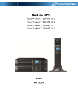
Unpack the equipment and remove all the packing materials and shipping cartoon (see figure 2 for
unpacking 5000 & 6000 VA UPS and External battery cabinets).
Note! Do not lift the UPS or External Battery Cabinets from the front panel.
Figure 2. Unpacking 5000/6000 VA UPS and external battery cabinet.
Discard or recycle the packaging in a responsible manner, or store it for future use.
Place the cabinet in a protected area that has adequate airflow and is free of humidity, flammable gas,
and corrosion.

Page 6
9130 UPS-EN
2. Installation
2.3 Checking the Accessory Kit
Verify that the following additional items are included with the UPS:
UPS user’s guide l
Software Suite CD l
USB cable l
RS232 cable l
ENGLISH
EATON 9130 UPS
5000 - 6000 VA
User's guide
Copyright © 2009 EATON
All rights reserved.
EATON
8609 6 Forks Road
Raleigh, NC 27615 U.S.A.
Toll Free: 1.800.356.5794 or 919.872.3020
Service and support:
United States: 1-800-843-9433 or 1-919-870-3028
Canada: 1-800-461-9166 ext 260
All other countries: Call your local service representative
E-mail: [email protected]
9130 UPS-EN
Figure 3. UPS Accessory kit.
If you ordered an optional Extended Battery Module (EBM), verify that the following additional item is
included with the EBM:
EBM user’s guide l
Power cable l
Figure 4. EBM Accessory kit.
Discard the EBM user’s guide if you are installing the EBM with a new UPS at the same time.
Use the UPS user’s guide to install both the UPS and the EBM.
2.4 Product Installation
The cabinet is heavy (see page 31). Removing the cabinet from its carton requires a minimum
of two people.
To install the cabinet:
1. Place the UPS on a flat, stable surface in its final location.
2. Always keep 150mm of free space behind the UPS rear panel.
3. If installing additional cabinets, place them next to the UPS in their final location.

Page 7
9130 UPS-EN
ENGLISH
2. Installation
2.5 Connecting the internal battery
Do not make unauthorized changes to the UPS; otherwise, damage may occur to your
equipment and void your warranty.
Do not connect the UPS to utility until installation is completed.
To install the UPS:
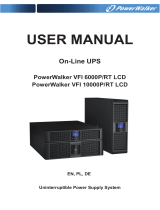
1. Remove the UPS front cover (see figure 5).
To remove the cover:
Remove the 2 fixing screws on the bottom of the cover.
Push upon the bottom of the cover and pull the cover toward you to unclip it from the cabinet.
A ribbon cable connects the LCD control panel to the UPS. Do not pull on the cable or
disconnect it.
Figure 5. Removing the UPS front cover.
A small amount of arcing may occur when connecting the internal batteries. This is normal and
will not harm personnel. Connect the cables quickly and firmly.
2. Connect the internal battery connector (see figure 6).
Connect the black connectors together.
Press the two parts tightly together to ensure a proper connection.
Figure 6. Connecting the UPS internal batteries.
3. Replace the UPS front cover.
To replace the cover, verify that the ribbon cable is protected, then insert the clips on the back of
the cover into the cabinet and push firmly to snap the cover into place.
Put back the 2 fixing screws on the bottom of the front.
4. If you are installing power management software, connect your computer to one of the
communication ports or optional connectivity card (see page 21). For the communication ports, use
an appropriate cable (not supplied).
5. If an remote power-off (disconnect) switch is required by local codes, see "Remote Power-off" (RPO)
on page 22 to install the RPO switch before powering on the UPS.
6. If you are installing EBM(s), continue to the following section, "Connecting the EBM(s)". Otherwise,
continue to "Installation requirements" on page 8.

Page 8
9130 UPS-EN
2. Installation
2.6 Connecting the EBM(s)
To install the optional EBM(s) for a UPS:
A small amount of arcing may occur when connecting an EBM to the UPS. This is normal
and will not harm personnel. Insert the EBM cable into the UPS battery connector quickly and
firmly.
1. Plug the EBM cable(s) into the battery connector(s) as shown in figure 7. Up to four EBMs may be
connected to the UPS.
2. Verify that the EBM connections are tight and that adequate bend radius and strain relief exist for
each cable.
3. When using external battery cabinets, the number of EBMs should be set throw the LCD panel in the
"Battery settings" section, see "Configuring battery settings" on page 20.
4. Continue to "Installation requirements" on page 8.
Figure 7. Connecting the EBMs.
2.7 Installation requirements
Required protective devices and cable cross-sections
1. Recommended upstream protection (see figure 8)
Table 1. Upstream circuit breaker rating
UPS power rating Upstream circuit breaker
5000 VA / 6000 VA D curve – 40 A
G N L
N
L
Figure 8. Upstream protection.
2 poles circuit breaker
To UPS input source
and/or Bypass source.

Page 9
9130 UPS-EN
ENGLISH
2. Installation
2. Required cable cross-sections
Table 2. Cable cross sections
UPS power rating
5000 VA / 6000 VA
Minimum of section
required
Terminal-block capacity
Phase and neutral solid or
stranded wire
6 mm²
AWG 10
10 mm²
AWG 8
Earthing solid or stranded
wire
6 mm²
AWG 10
10 mm²
AWG 8
2.8 Installation depending on the system earthing arrangement (SEA)
UPS with common Normal and Bypass inputs (Figure 9)
Change in SEA between upstream and downstream or galvanic isolation required (Figure 10)
UPS with separate Normal and Bypass inputs (Figure 11)
Change in SEA between upstream and downstream or galvanic isolation required (Figure 12)
The transformer is not necessary if:
Normal and Bypass inputs are connected to the same source, l
and wires cross sections and wires lengths on Input and Bypass inputs are identical, l
and upstream protection is provided by only one switch with RCD (residual current l
device) for Input and Bypass inputs.
*
Main low
voltage
switchboard
(MLVS)
Bypass
Bypass
Bypass
Input
Input
Input
Load
Load
Load
Main low
voltage
switchboard
(MLVS)
Main low
voltage
switchboard
(MLVS)
Bypass
Input
Load
Main low
voltage
switchboard
(MLVS)
Output
Output
Output
Output

Page 10
9130 UPS-EN
2. Installation
UPS with separate Input and Bypass inputs, supplied by separate sources (Figure 13)
Change in SEA between upstream and downstream or galvanic isolation required (Figure 14)
8
10
11
Frequency converter (without Bypass input) (Figure 15)
Configuration used when the frequency of the application differs from the Mains, example: marine
requirements.
Bypass
Bypass
Bypass
Input
Input
Input
Input
Load
Load
Load
Load
Main low
voltage
switchboard
(MLVS)
MLVS1
MLVS1
MLVS1
MLVS2
MLVS2
MLVS2
Output
Output
Output
Output

Page 11
9130 UPS-EN
ENGLISH
3. Power cables connection & Startup
This section explains:
Access to terminal block l
Common input sources connection l
Separate input sources connection l
Frequency converter connection l
UPS Initial startup l
3.1 Access to terminal block
1. Access to terminal block: remove the 4 screws of the terminal block cover (see figure 16)
Figure 16. Access to terminal block.
High leakage current: l
Earth connection essential before connecting supply.
3.2 Common input sources connection
This type of connection must be carried out by qualified electrical personnel
Before carrying out any connection, check that the upstream protection device Input source is
open ("O") (OFF).
Always connect the earthing wire first.
JP L N L N L N
BYPASS INPUT OUTPUT
1 - Make sure the metal jumper is connected
(see figure 17).
2 - Insert the Input source cable through the cable
gland.
3 - Connect the 3 cables to the Input source terminal
block.
4 - Insert the Output cable through the cable gland.
5 - Connect the 3 cables to the output terminal
block.
6 - Put back and secure the terminal block cover
with the 4 screws.
7 - Tightened the cable glands.
Figure 17.

Page 12
9130 UPS-EN
3. Power cables connection & Startup
3.3 Separate input sources connection
This type of connection must be carried out by qualified electrical personnel.
Before carrying out any connection, check that the upstream protection device Input source is
open ("O") (OFF).
Always connect the earthing wire first.
JP L N L N L N
BYPASS INPUT OUTPUT
1 - Remove the metal jumper (see figure 18).
2 - Insert the Input source cable through the cable
gland.
3 - Connect the 3 cables to the Input terminal block.
4 - Insert the Bypass source cable through the cable
gland.
5 - Connect the 3 cables to the Bypass terminal
block.
6 - Insert the Output cable through the cable gland.
7 - Connect the 3 cables to the output terminal
block.
8 - Put back and secure the terminal block cover
with the 2 screws.
9 - Tightened the cable glands.
Figure 18.
3.4 Frequency converter connection
This type of connection must be carried out by qualified electrical personnel.
Before carrying out any connection, check that the upstream protection device Input source is
open ("O") (OFF).
Always connect the earthing wire first.
JP L N L N L N
BYPASS INPUT OUTPUT
1 - Remove the metal jumper (see figure 19).
2 - Insert the Input source cable through the cable
gland.
Do not connect anything to the Bypass
terminal block.
3 - Connect the 3 cables to the Input terminal block.
4 - Insert the Output cable through the cable gland.
5 - Connect the 3 cables to the output terminal
block.
6 - Put back and secure the terminal block cover
with the 2 screws.
7 - Tightened the cable glands.
Figure 19.

Page 13
9130 UPS-EN
ENGLISH
3. Power cables connection & Startup
3.5 UPS Initial Startup
To start up the UPS:
Verify that the total equipment ratings do not exceed the UPS capacity to prevent an overload
alarm.
1. Verify that the internal batteries are connected.
See "Connecting the internal battery" on page 7.
2. If optional EBMs are installed, verify that the EBMs are connected to the UPS.
See "Connecting the EBM(s)" on page 8.
3. Set the upstream circuit breaker (not included) to the "I" position (ON).
The UPS front panel display illuminates and shows a status of "UPS initializing..."
4. Verify that the UPS transfers to Standby mode ("UPS on standby").
5. Press the
button on the UPS front panel for at least one second.
The UPS front panel display changes status to "UPS starting..."
6. Check the UPS front panel display for active alarms or notices. Resolve any active alarms before
continuing. See "Troubleshooting" on page 34.
If the
indicator is on, do not proceed until all alarms are clear. Check the UPS status from the
front panel to view the active alarms. Correct the alarms and restart if necessary.
7. Verify that the
indicator illuminates solid, indicating that the UPS is operating normally and any
loads are powered.
The UPS should be in Normal mode.
8. Press the
ESC
button until the start screen appears.
9. If optional EBMs are installed, see "Configuring the UPS for EBMs" on page 20 to set the number of
installed EBMs.
10. To change any other factory-set defaults, see "Operation" on page 14.
If you are powering RCD type loads, with high inrush current, it is possible to first start on
bypass:
1. In standby mode, enable the user setting “Start on Bypass” (disabled by default).
2. Press the on button to start the UPS. The UPS will start on Bypass for 5~15 seconds, and then
transfer automatically to Normal mode.
Eaton recommends setting the date and time.
At initial startup, the UPS sets system frequency according to input line frequency (input
frequency auto-sensing is enabled by default). After initial startup, auto-sensing is disabled
until manually re-enabled by output frequency setting.
At initial startup, input voltage auto-sensing is disabled by default. When manually enabled
by output voltage setting, at the next AC startup the UPS sets output voltage according to
input line voltage. After the subsequent startup, auto-sensing is disabled until manually
re-enabled by output voltage setting.
11. If you installed an optional RPO, test the RPO function:
Activate the external RPO switch. Verify the status change on the UPS display.
Deactivate the external RPO switch and restart the UPS.
The internal batteries charge to 90 % capacity in less than 3 hours. However, Eaton
recommends that the batteries charge for 48 hours after installation or long-term storage. If
optional EBMs are installed, see the recharge times listed in table 24 on page 33.

Page 14
9130 UPS-EN
4. Operation
This chapter contains information on how to use the Eaton 9130, including front panel operation,
operating modes, UPS startup and shutdown, transferring the UPS between modes, retrieving the
Event Log, setting the power strategy, and configuring bypass settings, load segments, and battery
settings.
4.1 Control Panel Functions
The UPS has a four-button graphical LCD with backlight. It provides useful information about the UPS
itself, load status, events, measurements, and settings (see figure 20).
esc
Figure 20. Eaton 9130 Control Panel.
The button controls only the UPS output. The button has no effect on equipment
connected to the UPS.
Table 3 shows the indicator status and description.
Table 3 - Indicator Descriptions
Indicator Status Description
On The UPS is operating normally on bypass during High Efficiency
operation.
Green
Flashing A new information message is active.
On The UPS is in Battery mode.
Yellow
Flashing The battery voltage is below the warning level.
On The UPS is in Bypass mode.
Yellow
On The UPS has an active alarm or fault. See "Troubleshooting" on
page 33 for additional information.
Red
Changing the Language
Press and hold the first button on the left for approximately three seconds to select the language menu.
This action is possible from any LCD menu screen.
Display Functions
As the default or after 15 minutes of inactivity, the LCD displays the start screen.
The backlit LCD automatically dims after 15 minutes of inactivity. Press any button to restore the
screen.
Press any button to activate the menu options. Use the two middle buttons (
and ) to scroll through
the menu structure. Press the Enter (
) button to select an option. Press the
ESC
button to cancel or
return to the previous menu.
Power On Indicator (green)
On Battery Indicator (yellow)
Bypass Indicator (yellow)
Alarm Indicator (red)
On/Off Button
Escape Up Down Enter

Page 15
9130 UPS-EN
ENGLISH
4. Operation
The table 4 shows the basic menu structure.
Table 4. Menu Map for Display Functions
Main Menu Submenu Display Information or Menu Function
UPS Status Main status (mode and load) / Notice or Alarm status
(if any) / Battery status (state and charge level)
Event Log Displays up to 127 events and alarms.
The Event Log is also available through the serial port. See
"Retrieving the Event Log" on page 19.
Measurements Load W VA / Load A pf / Output V Hz / Input V Hz / Bypass V Hz /
Input Line Events / Battery V min
Control Go to Bypass Transfers the UPS system to internal Bypass mode.
When this command is active, the option changes to "Go to
Normal".
Start Battery Test Starts a manual battery test.
See "Testing New Batteries" on page 29.
Reset Error State Clears a "Battery Test Failed" alarm
Restore Factory Settings Returns all settings to original values
Identification UPS Type / Part Number / Serial Number / Firmware
Settings User Settings See Table 5 for details.
Service Settings This menu is password-protected.
User Settings
The following table displays the options that can be changed by the user.
Table 5. User Settings
Description Available Settings Default Setting
Change Language [English] [French] [Spanish] [German] [Russian]
Menus, status, notices, and alarms are in all
supported languages. UPS faults, Event Log data,
and settings are in English only.
English
User Password [Enabled] [Disabled]
If Enabled is selected, the password is USER.
Disabled
Audible Alarms [Enabled] [Disabled] Enabled
Set Date and Time
NOTE: time is a 24-hour
clock.
Set Year, Month, Day, Hours, Minutes
Date: yyyy/mm/dd
Time: hh:mm
2008/01/01
12:00
Signal Inputs Setup: [Not Used] [Force Bypass] [Remote
Shutdown] [Delayed Shutdown]
[On Generator] [Building Alarm 1]
Active: [High] [Low]
See "Programmable Signal Inputs" on page 24.
RS232-3: Not Used, High
cXSlot Serial: Delayed
Shutdown, High
cXSlot Signal: Remote
Shutdown, Low
Relay Configuration [UPS ok] [On Bypass] [On Battery] [Battery Low]
[Ext. Charger On]
See "Relay Output Contacts" on page 23.
Standard: UPS ok
RS232-1: Battery Low
RS232-8: On Battery
cXSlot-K1: On Battery
cXSlot-K2: Battery Low
cXSlot-K3: UPS ok
cXSlot-K4: On Bypass
Serial Port Configuration [1200 bps] [2400 bps] [9600 bps]
NOTE: USB communication requires 9600 bps.
RS232: 9600 bps
cXSlot: 9600 bps
Control Commands from
Serial Port
[Enabled] [Disabled] RS232: Enabled
cXSlot: Enabled
Output Voltage [208V] [220V] [230V] [240V] [Autosensing] 230 V
Output Frequency [50Hz] [60Hz] [Autosensing] Autosensing
Frequency Converter [Enabled] [Disabled]
If Enabled, the UPS operates as a frequency
converter, with bypass operation and all bypass-
related alarms disabled.
Disabled
Overload Alarm Level [10%] [20%] [30%] ... [100%]
These values affect alarm level only, not UPS
operation such as transfers or shutdown.
100 %
Generates the Output.
Overload alarm at the set
level.
Transfer to Bypass When
Overload*
[Immediate] [After Delay]
If Immediate, transfer occurs at load > 102 %.
If After Delay, transfer occurs according to table 20
on page 32.
After Delay

Page 16
9130 UPS-EN
4. Operation
Power Strategy [Normal] [High Efficiency]
See "Setting Power Strategy" on page 19.
Normal
Automatic start delay [No Delay] [Disabled] [1,2,...,32767 s]
To define if the load turns automatically on, with
the delay set after the utility return, if it has been
shutdown by:
- signal input with auto-restart option
- an XCP command with autorestart option
- battery under voltage state, or automatic on
battery shutdown command.
No Delay
Automatic on battery
shutdown
[Disabled] [No Delay] [1,2,...,32767 s]
To define if the load turns automatically off when
"UPS on battery" state activates.
Disabled
Start on Battery
NOTE: utility must be
present and output
enabled at initial UPS
startup.
[Enabled] [Disabled]
After initial startup, battery voltage must exceed
2.10 volts per cell to start on battery.
Enabled
Energy Saving Mode [Disabled] [50W] [100W] ... [1000W]
UPS output is turned off (after 5 min) if the UPS is
on battery and output power is below the selected
level.
Disabled
Remote Shutdown Delay [No Delay] [1s] [2s]...[10800s] No Delay
Delayed Shutdown Delay [No Delay] [1s] [2s]...[10800s] 120 s
On Battery Notice Delay [0] [1s] [2s]...[99s] 5 s
Site Wiring Fault Alarm [Enabled] [Disabled]
An active site wiring fault alarm prevents startup or,
if operating, forces operation to Battery mode and
disables bypass.
Enabled
Bypass Voltage Low
Limit*
[-4%] [-5%] ... [-20%] of nominal -15 % of nominal
Bypass Voltage High
Limit*
[+4%] [+5%] ... [+20%] of nominal +10 % of nominal
Qualify Bypass* [Never] [When in Spec] [Always on UPS Fault]
[Always]
When in Spec
Synchronization Window* [Sync Disabled] [±0.5 Hz] [±1.0 Hz] [±2.0 Hz]
[±3.0 Hz]
±3 Hz
Unsynchronized
Transfers*
[Enabled] [Disabled] Enabled
Number of Battery Strings [0] [1] [2] ... [10]
See "Configuring the UPS for EBMs" on page 18.
1
Battery Charge Mode [ABM Cycling] [Constant] ABM Cycling
Temperature
Compensated Charging
[Enabled] [Disabled]
If Disabled, the default charger voltages for 25 °C
(77°F) are assumed.
Enabled
Battery Charge % to
Restart
[Not Checked] [10] [20] ... [100]
If a percentage is selected, automatic restart (if
enabled) occurs when the battery’s charge reaches
the selected level.
Not Checked
Battery Low Alarm [Immediate] [2 min] [3 min] [5 min]
The "Battery Low" alarm triggers when the set
amount of backup time (approximately) remains in
the batteries. If set to Immediate, the alarm activates
at the same time as the "UPS on Battery" notice.
3 min
Automatic Battery Support
Tests
[Enabled] [Disabled]
See "Running Automatic Battery Tests" on page 20
Enabled
Deep discharge protection [Enabled] [Disabled]
Protection against deep discharge. If disabled, Eaton
warranty will be void.
Enabled
Start on Bypass [Disabled] [Enabled]
During start up sequence, transfer first on Bypass
(for 5~15 seconds) then transfer online.
Disabled
Ambient Temperature
Warning
[Enabled] [Disabled] Enabled
Predictive Maintenance
Notices
[Enabled] [Disabled] Enabled
Remote Power-off (RPO)
Input Polarity
[Open] [Closed] Open
* See "Configuring Bypass Settings" on page 19.

Page 17
9130 UPS-EN
ENGLISH
4. Operation
4.2 Operating Modes
The Eaton 9130 front panel indicates the UPS status through the UPS indicators (see figure 20 on page
14).
Normal Mode
During Normal mode, the
indicator illuminates solid and the UPS is powered from the utility.
The UPS monitors and charges the batteries as needed and provides filtered power protection to your
equipment.
The UPS may at times silently implement a High Alert mode, usually when incoming utility conditions
are unfavorable. In High Alert mode, the UPS disables the battery support test to ensure maximum
capacity from the batteries if needed. The UPS will remain in High Alert for 24 hours or until changed
by a Power Strategy command before returning to its previous mode.
Optional High Efficiency and Energy Saving settings minimize heat contribution to the rack
environment. See "User Settings" on page 15.
Battery Mode
When the UPS is operating during a power outage, the alarm beeps once every five seconds and the
indicator illuminates solid.
When the utility power returns, the UPS transfers to Normal mode operation while the battery
recharges.
If battery capacity becomes low while in Battery mode, the
indicator flashes slowly and the audible
alarm beeps once every second. If the "Battery Low" alarm is set, the indicator also illuminates
solid. This warning is approximate, and the actual time to shutdown may vary significantly.
Depending on the UPS load and the number of Extended Battery Modules (EBMs) connected,
the "Battery Low" warning may occur before the batteries reach 25 % capacity. See table 23 on
page 33 for estimated runtimes.
When utility power is restored after the UPS shuts down, the UPS automatically restarts.
Bypass Mode
In the event of a UPS overload or internal failure, the UPS transfers your equipment to utility power.
Battery mode is not available and your equipment is not protected; however, the utility power
continues to be passively filtered by the UPS. The indicator illuminates.
The UPS remains in Bypass mode for at least 5 seconds (if the bypass source remains acceptable). If
three transfers to Bypass occur within 10 minutes for any reason other than user command, the UPS
locks in Bypass for 1 hour or until any control button is pressed.
The UPS transfers to Bypass mode when:
the user activates Bypass mode through the front panel. l
the UPS detects an internal failure. l
the UPS has an overtemperature condition. l
the UPS has an overload condition listed in table 20 on page 32. l
The UPS shuts down after a specified delay for overload conditions listed in table 20 on page 32.
The UPS remains on to alarm the fault
Standby Mode
When the UPS is turned off and remains plugged into a power outlet, the UPS is in Standby mode.
The indicator is off, indicating that power is not available to your equipment. The battery recharges
when necessary, and the communication bay is powered.
If utility fails and output turns off due to drained batteries or UPS internal failure, the UPS alarms in
Standby mode and powers the communication bay for 1 hour 30 minutes or until battery voltage drops
below 1.75 volts per cell (whichever occurs first).
If utility fails while the UPS is in Standby mode, the logic power supply turns off in approximately
10 seconds.
If the UPS is waiting on commands and utility fails, unit and logic power turn off in approximately
30 seconds.

Page 18
9130 UPS-EN
4. Operation
4.3 UPS Startup and Shutdown
To start up or shut down the UPS, see:
"Starting the UPS" on page 18 l
"Starting the UPS on Battery" on page 18 l
"UPS Shutdown" on page 18 l
Starting the UPS
"Start on Bypass" settings can be used to power on capacitive loads.
To start the UPS:
1. Verify that the UPS power cord is plugged in.
2. Switch on utility power where the UPS is connected.
The UPS front panel display illuminates and shows a status of "UPS initializing...".
3. Verify that the UPS transfers to Standby mode ("UPS on standby").
4. Press the
button on the UPS front panel for at least one second.
The UPS front panel display changes status to "UPS starting...".
5. Check the UPS front panel display for active alarms or notices. Resolve any active alarms before
continuing. See "Troubleshooting" on page 34.
If the
indicator is on, do not proceed until all alarms are clear. Check the UPS status from the
front panel to view the active alarms. Correct the alarms and restart if necessary.
6. Verify that the
indicator illuminates solid, indicating that the UPS is operating normally and any
loads are powered.
The UPS should be in Normal mode.
7. Press the
ESC
button until the start screen appears.
Starting the UPS on Battery
Before using this feature, the UPS must have been powered by utility power with output enabled
at least once.
Battery start can be disabled. See the "Start on Battery" setting in "User Settings" on page 16.
To start the UPS on battery:
1. Press the
button on the UPS front panel until the UPS front panel display illuminates and shows
a status of "UPS starting...".
The UPS cycles through Standby mode to Battery mode. The
indicator illuminates solid. The
UPS supplies power to your equipment.
2. Check the UPS front panel display for active alarms or notices besides the "UPS on Battery" notice
and notices that indicate missing utility power. Resolve any active alarms before continuing. See
"Troubleshooting" on page 34.
Check the UPS status from the front panel to view the active alarms. Correct the alarms and restart
if necessary.
3. Press the
ESC
button until the start screen appears.
UPS Shutdown
To shut down the UPS:
1. Press the
button on the front panel for three seconds.
The UPS starts to beep and shows a status of "UPS off pending...". The UPS then transfers to
Standby mode, and the
indicator turns off.
Releasing the button before three seconds returns the UPS to its original operating mode.
2. Switch off utility power where the UPS is connected.
4.4 Transferring the UPS Between Modes
From Normal to Bypass Mode. Press any button to activate the menu options, then select CONTROL
and GO TO BYPASS.
From Bypass to Normal Mode. Press any button to activate the menu options, then select CONTROL
and GO TO NORMAL.

Page 19
9130 UPS-EN
ENGLISH
4. Operation
4.5 Retrieving the Event Log
To retrieve the Event Log through the display:
1. Press any button to activate the menu options, then select EVENT LOG.
2. Scroll through the listed events.
To retrieve the Event Log through the serial port:
1. From the communication device connected to the serial port, send one of the following command
sequences: ESC-L (ASCII characters 27 and 76) or ESC-I (ASCII characters 27 and 108).
The UPS returns a header containing the UPS identification (UPS type, part number, and serial
number), firmware version, and the current date and time, followed by the event history.
2. Use the connected communication device to view or print the information. The report is delivered in
ASCII format.
4.6 Setting Power Strategy
On the High Efficiency setting, the UPS operates normally on Bypass, transfers to inverter in less than
10 ms when utility fails, and transfers back to Bypass in 1 minute after utility returns.
High Efficiency operation is available after one minute of stable power.
To set the power strategy:
1. Press any button to activate the menu options, then select SETTINGS, USER SETTINGS, and POWER
STRATEGY.
2. Select HIGH EFFICIENCY or NORMAL, and ENTER to confirm.
4.7 Configuring Bypass Settings
The following settings are available for configuring Bypass operation.
Transfer to Bypass When Overload. The default forces a transfer to Bypass when any overload
condition occurs. You can configure the setting for a delayed transfer, with the amount of delay
determined by the amount of overload, as shown in table 20 on page 32.
Bypass Voltage Low Limit. The default disables a transfer to Bypass if the measured bypass voltage
level is below the nominal output voltage minus 15 %. You can configure the setting for another
percentage of nominal. This setting can be overruled by the "Qualify Bypass" setting.
Bypass Voltage High Limit. The default disables a transfer to Bypass if the measured bypass voltage
level is above the nominal output voltage plus 10 %. You can configure the setting for another
percentage of nominal. This setting can be overruled by the "Qualify Bypass" setting.
Qualify Bypass. The default allows a transfer to Bypass only when Bypass is within the following
specifications:
Bypass voltage is between the "Bypass Voltage Low Limit" and "Bypass Voltage High Limit" l
settings.
Bypass frequency is within nominal frequency ±3 Hz. l
the inverter is synchronized with Bypass when the "Unsynchronized Transfers" setting is l
disabled.
You can prohibit Bypass ("Never") or always allow Bypass with no specification checking ("Always").
For "Always on UPS Fault", transfer to Bypass is always made on UPS fault; otherwise, operation
proceeds as with the default setting.
Synchronization Window. The UPS tries to synchronize with Bypass when the Bypass frequency is less
than the value set for the "Synchronization Window" setting. When the Bypass frequency is more than
the set value, the UPS goes to nominal frequency. On Bypass the synchronization window is ±3 Hz. If
synchronization is disabled ("Sync Disabled"), the UPS will synchronize only when operating on Bypass.
Unsynchronized Transfers. The default allows an unsynchronized transfer to Bypass. You can configure
the setting to not allow such transfers. This setting can be overruled by the "Qualify Bypass" setting.

Page 20
9130 UPS-EN
4. Operation
4.8 Configuring Battery Settings
Set the UPS for the number of EBMs installed whether to run automatic battery tests, and automatic
restart configuration.
Configuring the UPS for EBMs
To ensure maximum battery runtime, configure the UPS for the correct number of EBMs:
1. Press any button on the front panel display to activate the menu options, then select SETTINGS,
USER SETTINGS, and NUMBER OF BATTERY STRINGS.
2. Use the
or buttons to select the number of battery strings according to your UPS configuration:
Table 6. EBM vs number of Battery strings
All UPS and EBM Cabinets Number of Battery Strings
UPS only (internal batteries) 1 (default)
UPS + 1 EBM 3
UPS + 2 EBMs 5
UPS + 3 EBMs 7
UPS + 4 EBMs 9
NOTE: if 0 is selected, no batteries are connected and all battery-related alarms are disabled.
NOTE: the UPS contains one battery string; each EBM contains two battery strings.
3. Press the
button to save the setting.
4. Press the
ESC
button until the start screen appears.
Running Automatic Battery Tests
Automatic battery tests run approximately every 30 days, unless disabled. During the test, the UPS
transfers to Battery mode and discharges the batteries for 25 seconds under the existing load.
The "UPS on Battery" notice and the "Battery Low" alarm do not activate during a battery test.
For automatic battery tests to run:
the "Automatic Battery Support Tests" setting must be enabled. l
the UPS must be in Normal mode, with no active alarms. l
the batteries must be fully charged. l
the bypass voltage must be acceptable. l
no manual battery test was initiated previously in the same charging cycle. l
To pass the battery test, the battery voltage must remain above the threshold value during discharge.
Configuring Automatic Restart
The UPS automatically restarts if utility returns after the output was shut off due to exhausted batteries,
a shutdown input signal, or automatic shutdown command.
You can set the load segment for the amount of time to delay the restart once utility returns, using the
"Automatic Start Delay" setting. You can also configure UPS restart to depend on the battery charge
level, using the "Battery Charge % to Restart" setting.
/