Page is loading ...

F-18
TRUE ONLINE DOUBLE
CONVERSION UPS
UPS USER MANUAL
1000VA/2000VA/3000VA
PREMIUM NETWORK &
INDUSTRIAL UPS

CONTENT
1. Safety and EMC Instructions ............................................................ 4
1.1 Installation .......................................................................................... 4
1.2 Operation .......................................................................................... 10
1.3 Maintenance, servicing and faults .................................................... 11
1.4 Transport .......................................................................................... 14
1.5 Storage ............................................................................................. 14
1.6 Standards ......................................................................................... 15
2. Description of Commonly Used Symbols ..................................... 16
3. Introduction ...................................................................................... 17
4. Connection ........................................................................................ 18
4.1 Inspection ......................................................................................... 18
4.2 Connection ....................................................................................... 18
4.3 Battery charge .................................................................................. 20
4.4 Operation procedure of external battery for long backup time model
(“S” model) ............................................................................................. 20
5. Operation .......................................................................................... 22
5.1 Display Panel ................................................................................... 22
5.2 Operating mode ................................................................................ 24
5.3 Turning on and Turning off UPS ...................................................... 30
5.4 LCD operation .................................................................................. 31
6. Trouble Shooting .............................................................................. 42
7. Maintenance ...................................................................................... 44
7.1 Operation .......................................................................................... 44
7.2 Storage ............................................................................................. 44
7.3 Battery Replace ................................................................................ 44
8. Technical Data .................................................................................. 45
8.1 Electrical specifications .................................................................... 45
8.2 Operating Environment .................................................................... 45
8.3 Typical backup time (Typical values at 25°C in minutes:) ................... 45
8.4 Dimensions and weights .................................................................... 46
9. Communication Port ........................................................................ 47
9.1 RS-232 and USB communication ports ........................................... 47
9.2 RS-232 port ...................................................................................... 47

9.3 USB port ........................................................................................... 48
9.4 Installing a Serial Network Management Card (optional) ................ 48
9.5 Dry Contact port ............................................................................... 48
10. Software .......................................................................................... 51
Appendix: Rear panel .......................................................................... 52

4
1. Safety and EMC Instructions
1.1 Installation
See installation instructions before connecting to the supply.
Condensation may occur if the UPS is moved directly from a cold to a
warm environment. The UPS must be absolutely dry before being
installed. Please allow an acclimatization time of at least two hours.
Do not install the UPS near water or in damp environment.
Do not install the UPS where it would be exposed to direct sunlight or
near heat.
Do not connect appliances or items of equipment which would overload
the UPS (e.g. laser printers, etc) to the UPS output.
Place cables in such a way that no one can step on or trip over them.
Assure to connect with the earth reliably.
Assure external battery source must be earthed.
Connect the UPS only to an earthed shockproof socket outlet.
The building wiring socket outlet (shockproof socket outlet) must be
easily accessible to close to the UPS.
With the installation of the equipment, the sum of the leakage current of
the UPS and the connected load does not exceed 3.5mA.
Do not block ventilation openings in the UPS’s housing. Ensure the air
vents on the front and rear of the UPS are not blocked. Allow at least
25cm of space on each side.
UPS has provided earthed terminal, in the final installed system
configuration, equipotential earth bonding to the external UPS battery
cabinets.
An appropriate disconnect device as short-circuit backup protection
should be provided in the building wiring installation. Please see the
disconnect device specification in chapter 4.2.
The equipment is powered by more than one source.
1.1.1 Inspection of Unit
Inspect the UPS upon receiving. If the UPS is apparently damaged during
the shipment, please keep the box and packing material in original form for
the carrier and notify the carrier and dealer immediately.
Please read carefully the following user manual and the safety
instructions before installing the unit or using the unit!

5
1.1.2 Unpacking the Cabinet
To unpack the system:
1. Open the outer carton and remove the accessories packaged with the
cabinet.
2. Carefully lift the cabinet out of the outer carton and set it on a flat, stable
surface.
3. Discard or recycle the packaging in a responsible manner, or store it for
future use.
1.1.3 UPS Setup
All model series are designed for tower and rack purpose. They can be
installed into a 19 inches equipment rack. Please follow the instruction for
Tower Setup and Rack-Mount Setup.
Tower setup
This series of UPS can be placed horizontally and vertically. As a tower
configuration, it is provided with the optional UPS stands to stabilize the
UPS when the UPS is positioned in vertical. The UPS stand must be
attached to the bottom of the tower. Use the following procedure to install
UPS in UPS stands.
1. Slide down the UPS vertically and put two UPS stands at the end of the
tower.
2. Place down the UPS into two stands carefully.
3. Pull out the LCD box and rotate it in a clockwise direction to 90 degree
and then push it back in the front panel

6
Rack-mount setup
The series can be installed in 19 inches racks. Both the UPS and external
battery enclosure need 2U of rack space.
Use the following procedure to install UPS in a rack.
1. Align the mounting ears with screw holes on the side of the UPS, and
tighten the screw.
2. Assemble the rack rails with the rack-mounting.
3. Slide in the UPS into the rack rail and lock it in the Rack-mounting.
4. Tighten the screw, and then the load can be connected.
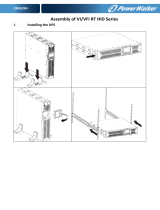
1.1.4 EBM Installation (Optional)
Connecting the EBM in Tower form:
1. Slide down the UPS and EBM vertically and place two UPS stands with the
extend part at the end of the tower.
2. Tighten the screw on the metal sheet for stabilization
3. Connect the Earth line from UPS (port A ) to EBM (port B)
4. Take off the front panel, and connect the battery terminal (A) from UPS to
EBM terminal (B) shown as below. Users need to remove the small gate(C)

7
on side of the front panel to allow the outlet wire of the EBM to pass through
the gate and then reassemble front panel.
B
A

8
Connecting the EBM in a rack form
1. Using the same method as assembling UPS in a rack form, assemble EBM
into the rack-mounting on the top or bottom of the UPS.
2. Connect the earth line from UPS (port A ) to EBM (port B )
3. Take off the LCD box, and unscrew the internal screws.
4. Take off the front panel, and connect the battery terminal (A) from UPS to
EBM terminal (B) shown as below. Users need to remove the small gate(C)
on side of the front panel to allow the outlet wire of the EBM to pass through
the gate and then reassemble front panel.
5. After installing the UPS into rack, the load can then be connected to UPS.
Please make sure the load equipment is turned off before plugging all loads
into the output receptacle
Connecting the Multiple EBMs
1000VA/1500VA/2000VA and 3000VA UPS include external battery port that
allows users to connect multiple EBM in order to provide additional backup
time. Follow the procedure to install multiple EBM as below.
A
B
5

9
Connecting multiple EBMs in Tower form
1. Connect Earth line between UPS and the first EBM, and then connect Earth
Line between the first EBM and the second EBM.
2. Take off the front panel, and connect the battery terminal (A) from UPS to
EBM terminal (B) shown as below. And then connect the battery terminal
(D) from the first EBM to the battery terminal (E) from the second EBM.
Users need to remove the small gate(C) on side of the front panel to allow
the outlet wire of the EBM to pass through the gate and then reassemble
front panel.
Connecting the Multiple EBMs in rack form
1. Connect Earth line between UPS and the first EBM, and then connect
Earth Line between the first EBM and the second EBM.
2. Take off the front panel, and connect the battery terminal (A) from UPS to
EBM terminal (B) shown as below. And then connect the battery terminal
(D) from the first EBM to the battery terminal (E) from the second EBM.
Users need to remove the small gate(C) on side of the front panel to allow
the outlet wire of the EBM to pass through the gate and then reassemble
front panel.

10
Note: Three or more EBMs can be connected to the UPS in the same way as
shown above.
Note: After connect the EBMs, please do not forget to set the number of
EBMs on LCD, if use the nonstandard EBMs,
please call local dealer or
distributor for setting method.
1.2 Operation
Do not disconnect the mains cable on the UPS or the building wiring
socket (grounded shockproof socket) during operation as this would
remove the ground to the UPS and of all connected loads.
The UPS features its own, internal current source (batteries). You may be
electric shock when you touch the UPS output sockets or output terminal
block even if the UPS is not connected to the building wiring socket.
In order to fully disconnect the UPS, first press the OFF button to turn off
the UPS, then disconnect the mains lead.
Ensure that no liquid or other foreign objects can enter the UPS.
Do not remove the enclosure. This system is to be serviced by qualified
service personnel only.
Remove the protective panel only after disconnecting the terminal
connections.
Use No. 12 AWG (for 3KS input wire), 90°C copper wire and 4.4 lb-in
Torque force when connecting to terminal block.

11
Use No. 10AWG (for all models battery wire), 90°C copper wire and
Anderson PP45 connectors for user’s external battery cabinet.
1.3 Maintenance, servicing and faults
The UPS operates with hazardous voltages. Repairs may be carried out
only by qualified maintenance personnel.
Caution - risk of electric shock. Even after the unit is disconnected from
the mains power supply (building wiring socket), components inside the
UPS are still connected to the battery which are potentially dangerous.
Before carrying out any kind of service and/or maintenance, disconnect
the batteries. Verify that no current is present and no hazardous voltage
exists in the capacitor or BUS capacitor terminals.
Batteries must be replaced only by qualified personnel.
Caution - risk of electric shock. The battery circuit is not isolated from the
input voltage. Hazardous voltages may occur between the battery
terminals and the ground. Verify that no voltage is present before
servicing!
Batteries have a high short-circuit current and pose a risk of shock. Take
all precautionary measures specified below and any other measures
necessary when working with batteries:
remove all jewellery, wristwatches, rings and other metal objects
use only tools with insulated grips and handles.
When changing batteries, replace with the same quantity and the same
type of batteries.
Do not attempt to dispose of batteries by burning them. It could cause
explosion.
Do not open or destroy batteries. Effluent electrolyte can cause injury to
the skin and eyes. It may be toxic.
Please replace the fuse only by a fuse of the same type and of the same
amperage in order to avoid fire hazards.
Do not dismantle the UPS, except the qualified maintenance personnel.
1.3.1 UPS and Battery Care
For the best preventive maintenance, keep the area around the UPS clean
and dust-free. If the atmosphere is very dusty, clean the outside of the system

12
with a vacuum cleaner. For long battery life, keep the UPS at an ambient
temperature of 25°C (77°F)
1.3.2 Storing the UPS and Batteries
When the UPS is intended to store for a long period, recharge the battery
every 6 months by connecting the UPS to utility power. The batteries charge
to 90% capacity in approximately 4 hours. However, it is recommended that
the batteries charge for 48 hours after long-term storage.
1.3.3 Time to Replace Batteries
When the discharging time is less than 50% of specified after full charged, the
battery may need to be replaced. Please check the battery connection or
contact your local dealer to order new battery.
WARNING:
Turn off the UPS and disconnect the utility power cord from the wall outlet.
Servicing should be performed by qualified service personnel
knowledgeable of batteries and required precautions. Keep unauthorized
personnel away from batteries
Batteries can present a risk of electrical shock or burn from high short
circuit current. The following precautions should be observed:
1. Remove watches, rings, or other metal objects.
2. Use tools with insulated handles.
3. Do not lay tools or metal parts on top of batteries.
4. Wear rubber gloves and boots.
5. Disconnect the charging source prior to connecting or disconnecting
battery terminal.
When replacing batteries, replace with the same type and number of
batteries or battery packs. Contact your service representative to order new
batteries.
Do not dispose of battery in a fire. Batteries may explode when exposed to
flame.
Proper disposal of batteries is required. Refer to your local codes for
disposal requirements.
Do not open or mutilate the battery. Released toxic electrolyte is harmful to
skin and eyes.
Note: If you are not qualified service personnel to replace the battery, do not
attempt to open the battery cabin. Please call local dealer or distributor
immediately.

13
1.3.4 Replacing UPS Internal Batteries
Follow the steps and Charts as below to replace batteries:
1. Take off the LCD box, and remove the screws.
2. Slide and Pull the front panel leftward and then take it off.
3. Disconnect the cable from the UPS and battery pack.
4. Remove the right inner battery bracket.
5. Pull the battery pack out onto flat area.
6. Install new battery pack into UPS.
7. Screw up the battery bracket and reconnect the battery cable A and B
8. Re-install the front panel back to UPS.
5
7

14
1.3.5 Testing New Batteries
For a battery test, please check:
The batteries must be fully charged.
The UPS must be in Normal mode with no active alarms.
Don’t take on/off the load.
To test batteries:
1. Connect the UPS to utility power for at least 48 hours to charge the
batteries.
2. Select “Start battery test” by pressing on the menu of “Control” to start
the battery test on line mode or HE mode.
1.3.6 Recycling the Used Battery:
To recycle properly the used battery, please do not discard the UPS, battery
pack and batteries into the trash bin. Please follow your local laws and
regulations; you may contact your local recycling waste management center
for further information to dispose properly of the used UPS, battery pack, and
batteries.
1.4 Transport
Please transport the UPS only in the original packaging (to protect against
shock and impact).
1.5 Storage
The UPS must be stockpiled in the room where it is ventilated and dry.
Warning:
Never dispose the batteries in a fire. It may explode.
Do not open or mutilate the batteries. Released electrolyte is harmful to
the skins and eyes. It may be toxic. A battery can present a risk of
electrical shoc
k and high short circuit current.

15
1.6 Standards
* Safety
IEC/EN 62040-1
* EMI
Conducted Emission..........................:IEC/EN 62040-2 Category C1
Radiated Emission.............................:IEC/EN 62040-2 Category C1
Harmonic Current...............................:IEC/EN 61000-3-2
Voltage Fluctuation and Flicker..........:IEC/EN 61000-3-3
*EMS
ESD...................................................:IEC/EN 61000-4-2 Level 3
RS.....................................................:IEC/EN 61000-4-3 Level 3
EFT....................................................:IEC/EN 61000-4-4 Level 4
SURGE.............................................:IEC/EN 61000-4-5 Level 4
CS……………………………………...:IEC/EN 61000-4-6 Level 3
MS……………………………………..: IEC/EN 61000-4-8 Level 3
Voltage Dips………………………….: IEC/EN 61000-4-11
Low Frequency Signals.....................:IEC/EN 61000-2-2

16
2. Description of Commonly Used Symbols
Some or all of the following symbols may be used in this manual. It is advisable to
familiarize yourself with them and understand their meaning:

17
3. Introduction
This On-Line-Series is an uninterruptible power supply incorporating
double-converter technology. It provides perfect protection specifically for
Novell, Windows NT and UNIX servers.
The double-converter principle eliminates all mains power disturbances. A
rectifier converts the alternating current from the socket outlet to direct
current. This direct current charges the batteries and powers the inverter. On
the basis of this DC voltage, the inverter generates a sinusoidal AC voltage,
which permanently supplies the loads.
Computers and periphery are thus powered entirely by the mains voltage. In
the event of power failure, the maintenance-free batteries power the
inverter.
This manual covers the UPS listed as follows. Please confirm whether it is
the model you intend to purchase by performing a visual inspection of the
Model No. on the rear panel of the UPS.
“S” Model: Extended backup time
Model No. Type Model No. Type
1K
Standard
1KS
Extended backup
time
1.5K 1.5KS
2K 2KS
3K 3KS

18
4. Connection
4.1 Inspection
Inspect the packaging carton and its contents for damage. Please inform the
transport agency immediately should you find signs of damage.
Please keep the packaging in a safe place for future use.
Note: Please ensure that the incoming feeder is isolated and secured to
prevent it from being switched back on again.
4.2 Connection
(1) UPS Input Connection
If the UPS is connected via the power cord, please use a proper socket with
protection against electric current, the user can refer to below table. If the
UPS is connected via wires, it is recommended to select the 2.5mm
2
wire,
and the “GND” terminal should be grounded first.
The UPS System has no input breaker on the standard cabinet. When
installing the UPS, the user needs to connect the external breakers and
protective components in the input terminals. It is recommended to select
the NFB(Non-Fuse Breaker) instead of the traditional combination kit
including breaker and fuse.
When selecting the NFB, the user can refer to below table.
Model No.
UPS INPUT NFB & Power Cord & Socket
VOLTAGE CURRENT
1K(S) 300Vac 10A
1.5K(S) 300Vac 12A
2K(S) 300Vac 16A
3K(S) 300Vac 20A
The system may be installed and wired only by qualified electricians
in accordance with applicable safety regulations!
When installing the electrical wiring, please note the nominal
amperage of your incoming feeder
.

19
(2) UPS Output Connection
The output of the UPS is IEC socket-types. Simply plug the load power cord
to the output sockets to complete connection. Use one cord for every 5A
load.
Model No. Output Socket (pcs)
1K(S)/1.5K(S)/ 2K(S) 8 * IEC320 C13
3K(S) 8 * IEC320 C13 + 1 * C19
The wiring configuration is shown as the
following procedure:
a) Remove the small cover of the terminal block
b) Use 2.5mm
2
wires for wiring configuration
c) Upon completion of the wiring configuration,
please check whether the wires are securely
affixed
d) Put the small cover back to the rear panel
(3) EPO Connection:
User can select the polarity of EPO, EPO is Normally close as default setting.
NO
Normally the EPO connector is open on the rear panel. Once the connector is
closed with a wire, the UPS would stop the output until the EPO status is disabled.
Disable the EPO status Enable the EPO status
Connection diagram
Caution:
Do not connect equipment which would overload the UPS system (e.g. laser
printers)

20
NC
Normally the EPO connector is closed with a wire on the rear panel. Once
the connector is open, the UPS would stop the output until the EPO status is
disabled.
Enable the EPO status Disable the EPO status
4.3 Battery charge
Fully charge the batteries of the UPS system by leaving the UPS system
connected to the mains for 1-2 hours. You may use the UPS system directly
without charging it but the stored energy time may be shorter than the
nominal value specified.
4.4 Operation procedure of external battery for long backup
time model (“S” model)
(1) Use the battery pack with voltage: 36VDC for 1KS (12V
3
batteries),
48VDC for 1.5KS/ 2KS (12V
4
batteries), 72VDC for 3KS (12V
6
batteries). Connection of batteries more than or less than required
will cause abnormality or permanent damage.
(2) One hard wiring type battery terminal on the rear panel is used for
connecting the battery pack.
(3) The battery connection procedure is very important. Any
incompliance may result in the risk of electric shock. Therefore, the
following steps must be strictly complied with.
(4) Make sure the mains input is cut off, if there is a battery breaker then
turn it off first.
(5) Remove front panel, connect the battery via Anderson PP45
connectors. Prepare the battery cable which should be able to carry
the current of >50A for all models, the cross section area should be
great than 4 mm
2
for all model. And battery wire color is
recommended as following:
GND
Red wire Green/Yellow wire Black wire
/