Page is loading ...

EN
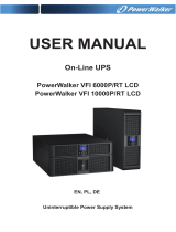
IMPORTANT SAFETY INSTRUCTIONS
SAVE THESE INSTRUCTIONS – This manual contains important instructions for
models PowerWalker VI 1000/1500/2000/3000 RT LCD that should be followed
during installation and maintenance of the UPS and batteries.
• This product is specially designed for PCs and it is not recommended for use in
any life-supporting system and other specific important equipment.
• This equipment can be operated by any individual with no previous training.
• Do not plug household appliances such as hair dryers to UPS receptacles.
• This unit intended for installation in a controlled environment (temperature
controlled, indoor area free of conductive contaminants). Avoid installing the
UPS in locations where there is standing or running water, or excessive
humidity.
• Risk of electric shock, do not remove cover. No user serviceable parts inside.
Refer servicing to qualified service personnel.
• The utility power outlet shall be near the equipment and easily accessible. To
isolate UPS from AC input, remove the plug from the utility power outlet.
• If UPS is to be stored for a long time, it is recommended to recharge the
batteries (by connecting the utility power to UPS, switch “ON”), once a month for
24 hours to avoid a full battery discharge.
• Please do not use the UPS in excess of the rated load capacity.
• The UPS contains one or more large-capacity batteries. So the shell shall not be
opened, otherwise such dangers as electric shock will be caused. If any internal
overhaul or replacement of the battery is required, please contact the distributor.
• The internal short circuiting of the UPS will lead to dangers such as electric
shock or fire, therefore, no water containers (such as a water glass) shall be
placed on the top of the UPS so as to avoid such dangers as electric shock.
• Do not dispose of battery or batteries in a fire. The battery may explode.
• Do not open or mutilate the battery or batteries. Released electrolyte is harmful
to the skin and eyes. It may be toxic.
• Icon Φ on the rating label stands for phase symbol.
• A battery can present a risk of electrical shock and high short circuit current.
The following precautions should be observed when working on batteries :

EN
• Remove watches, rings, or other metal objects from the hand.
• Use tools with insulated handles.
• Servicing of batteries should be performed or supervised by personnel
knowledgeable of batteries and the required precautions. Keep unauthorized
personnel away from batteries.
• When replacing batteries, replace with the same type and number of the sealed
lead-acid batteries.
• The maximum ambient temperature rating is 40°C.
• This pluggable type A equipment with battery already installed by the supplier is
operator installable and may be operated by laymen.
• During the installation of this equipment it should be assured that the sum of the
leakage currents of the UPS and the connected loads does not exceed 3.5mA.
• Attention, hazardous through electric shock. Also with disconnection of this unit
from the mains, hazardous voltage still may be accessible through supply from
battery. The battery supply should be therefore disconnected in the plus and
minus pole of the battery when maintenance or service work inside the UPS is
necessary.
• The mains socket outlet that supplies the UPS shall be installed near the UPS
and shall be easily accessible.
• In case smoke is found coming out from the device, please cut off the power
supply quickly and contact the distributor.
• Do not keep or use this product in any of the following environments:
o Any area with combustible gas, corrosive substance or heavy dust.
o Any area with extraordinarily high or low temperature (above 40˚C or
below 0˚C) and humidity of more than 90%.
o Any area exposed to direct sunshine or near any heating apparatus.
o Any area with serious vibrations.
o Outdoor.
• In the event that there is fire occurring in the vicinity, please use dry-power
extinguishers. The use of liquid extinguishers may give rise to the danger of
electric shock.

EN
1. Introduction
This line-interactive series is compact and pure sine wave UPS and it is designed
for essential applications and environment, such as desktops, servers,
workstations, and other networking equipments. These models are available in
the output ratings of 1000VA, 1500VA, 2000VA and 3000VA. The series protects
your sensitive electronic equipments against power problems including power
sags, spike, brownouts, line noise, undervoltage, overvoltage and blackouts.
The series is convertible to rack and tower forms. It can be placed either in Rack
2U or Tower form. The front panel of the UPS includes LCD display and four
control buttons that allow users to monitor, configure and control the units. On
LCD, it also includes a LCD graphical bar, two status indications and four alarm
indications. A control button from the front panel allows users to silence off the AC
fail alarm and initiate the UPS self test sequence as well. The UPS case for
1000VA ~ 3000VA is made of metal. This series is powered from the AC mains
and supply AC outputs via receptacles on the rear panel. Communication and
control of UPS is available through serial or USB ports located on the rear panel.
The serial port will support communications directly with a server and offer
dry-contacts.
Features:
Microprocessor control guarantees high reliability
High frequency design
Built-in boost and buck AVR
Easy battery replacement design
Selectable input and output range
Cold start capability
Built-in Dry contact/RS-232/USB communication port
Optional SNMP module allows web-based remote or monitoring management
Enable to extend runtime with scalable external battery module(EBM)
Overload, short-circuit, and overheat protection
Rack/Tower 2-in-1 Design
19 inches rack mount available for all models

EN
2. Circuit Configuration and Commonly used
Symbols
Following figure shows the basic internal circuit configuration of the UPS
2.1 Description of Commonly Used Symbols
Some or all of the following Notations may be used in this manual and may
appear in your application process. Therefore, all users should be familiar with
them and understand their explanations.
Table1. Description of Commonly Used Symbols
Symbol Description
Alert you to pay special attention
Caution of high voltage
Alternating current source (AC)
Direct current source(DC)
Protective ground
Recycle
Keep UPS in a clear area

EN
3. Installation
3.1 Inspection of Unit
Inspect the UPS upon receiving. If the UPS is apparently damaged during the
shipment, please keep the box and packing material in original form for the
carrier and notify the carrier and dealer immediately.
3.2 Unpacking the Cabinet
To unpack the system:
1. Open the outer carton and remove the accessories packaged with the
cabinet.
2. Carefully lift the cabinet out of the outer carton and set it on a flat, stable
surface.
3. Discard or recycle the packaging in a responsible manner, or store it for
future use.
Package content: UPS, Input Power Cord, 2x IEC cable, Tower Holder,
Rack Ears, EPO Plug, USB cable, Software CD, manual
3.3 UPS Setup
All model series are designed for tower and rack purpose. They can be
installed into a 19 inches equipment rack. Please follow the instruction for
Tower Setup and Rack-Mount Setup.
Tower setup
This series of UPS can be placed horizontally and vertically. As a tower
configuration, it is provided with the optional UPS stands to stabilize the UPS
when the UPS is positioned in vertical. The UPS stand must be attached to the
bottom of the tower.

EN
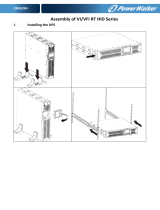
Use the following procedure to install UPS in UPS stands.
1. Slide down the UPS vertically and put two UPS stands at the end of the
tower.
2. Place down the UPS into two stands carefully.

EN
3. Pull out the LCD box and rotate it in a clockwise direction to 90 degree and
then push it back in the front panel.

EN
Rack-mount setup
The series can be installed in 19 inches racks. Both the UPS and external
battery enclosure need 2U of valuable rack space.
Use the following procedure to install UPS in a rack.
1. Align the mounting ears with screw holes on the side of the UPS, and
tighten the screw.
2. Assemble the rack rails with the rack-mounting.

EN
3. Slide in the UPS into the rack rail and lock it in the rack enclosure.
4. Tighten the screw, and the load can then be connected.

EN
3.4 EBM Installation (Optional)
Connecting the EBM in Tower form:
1. Slide down the UPS and EBM vertically and place two UPS stands with the
extend part at the end of the tower.
2. Tighten the screw on the metal sheet for stabilization
3. Connect the Earth line from UPS (port A ) to EBM (port B)
B
A

EN
4. Take off the front panel, and connect the battery terminal (A) from UPS to
EBM terminal (B) shown as below. Users need to remove the small gate(C)
on side of the front panel to allow the outlet wire of the EBM to pass
through the gate and then reassemble front panel.
Connecting the EBM in a rack form
1. Using the same method as assembling UPS in a rack form, assemble EBM
into the rack-mounting on the top or bottom of the UPS.
B
A
C

EN
2. Connect the earth line from UPS (port A ) to EBM (port B )
3. Take off the LCD box, and unscrew the internal screws.
A
B
Unscrew
Unscrew

EN
4. Take off the front panel, and connect the battery terminal (A) from UPS to
EBM terminal (B) shown as below. Users need to remove the small gate(C)
on side of the front panel to allow the outlet wire of the EBM to pass
through the gate and then reassemble front panel.
5. After installing the UPS into rack, the load can then be connected to UPS.
Please make sure the load equipment is turned off before plugging all loads
into the output receptacle.
Connecting the Multiple EBMs
1000VA/1500VA/2000VA and 3000VA UPS include external battery port that
allows users to connect multiple EBM in order to provide additional backup
time. Follow the procedure to install multiple EBM as below.
B
A
C

EN
Connecting multiple EBMs in Tower form
1. Connect Earth line between UPS and the first EBM, and then connect Earth
Line between the first EBM and the second EBM.
2. Take off the front panel, and connect the battery terminal (A) from UPS to
EBM terminal (B) shown as below. And then connect the battery terminal (D)
from the first EBM to the battery terminal (E) from the second EBM. Users
need to remove the small gate(C) on side of the front panel to allow the
outlet wire of the EBM to pass through the gate and then reassemble front
panel.
B
C
A
D
E

EN
Connecting the Multiple EBMs in rack form
1. Connect Earth line between UPS and the first EBM, and then connect Earth
Line between the first EBM and the second EBM.
2. Take off the front panel, and connect the battery terminal (A) from UPS to
EBM terminal (B) shown as below. And then connect the battery terminal (D)
from the first EBM to the battery terminal (E) from the second EBM. Users
need to remove the small gate(C) on side of the front panel to allow the
outlet wire of the EBM to pass through the gate and then reassemble front
panel.
Note: Three or more EBMs can be connected to the UPS in the same way as shown
above.
E
B
C
A
D

EN
3.5 UPS Initial Startup
To start up the UPS:
1. Verify that the internal batteries are connected. If optional EBMs are
installed, verify that the EBMs are connected to the UPS.
2. Plug the equipment to be protected onto the UPS, but do not turn on the
protected equipment.
3. Plug in the UPS input power cord. The UPS front panel display illuminates
and UPS status display shows “STbY”
4. Press and hold the button more than 3 seconds. The UPS status
display changes to “NORM”
6. Check the UPS display for active alarms or notices. Resolve any active
alarms before continuing. See “Troubleshooting”
8. If optional EBMs are installed, see “Configuring UPS for EBM numbers” on
page 21 to set the number of installed EBMs.
9. To change any other factory-set defaults, see “Operation”
Note: At initial startup, the UPS sets system frequency according to input line
frequency.

EN
4. Operation
4.1 Display Panel
The UPS has a four-button graphical LCD with dual color backlight. Standard
back-light is used to light up the display with black text and a blue background.
When the UPS has a critical alarm, the backlight changes the background to
red. See Figure below:
Control Buttons functions:
There are four buttons on the control panel.
ON/OFF
UPS Test /Alarm Silence
Select
Enter

EN
The following table describes the functions of the LCD control buttons.
Table2. Description of control button
Control
Button
Switch Function
ON/OFF
--To turn on/off the UPS
Press and hold the button more than 3 seconds.
--To release the UPS from faulty mode
Cut off input power and then press and hold the
button more than 2 seconds to shut down the
UPS.
UPS Test
Alarm Silence
--To perform basic function test
Press and hold the button for 3 seconds.
--To perform Battery life test
Press and hold the button for 10 seconds.
-- To disable alarm buzzer
Press the button for one second.
Select
Press the Select button
to select the settings
value one by one
Enter
-- Enter settings mode
Press and hold the button more than 3 seconds.
-- Enter settings item
Press and hold the Enter button more than one
second, the UPS allows users to configure the
settings, and the settings string will flash.
-- Confirm settings
Press and hold the Enter button for one second.
-- Exit Settings mode
Press and hold the Enter button for 3 seconds
or button for 0.5 second.
Note: Ensure the battery is fully charged during line mode when conducting
functional tests.
Note: A list of events shown as below is not able to disable alarm buzzer:
Low Battery, Fan Failed, Fan Fault Time Out, and Overheat.
Note: User can disable the alarm buzzer when it’s sounding, but an alarm will
still sound when a new alarm event is encountered.

EN
LCD display functions:
The following table describes the functions of the LCD display.
Table3. Description of LCD display function
No. Description Function
Input frequency and
voltage
Indicate the value of input frequency and voltage
Input plug indicator
Light on when the input power is at no loss.
Output frequency
and
voltage
Indicate the value of output frequency and
voltage
Output plug indicator
The UPS has two groups of outlets. The output
plug indicator will light on if there is output
power respectively.
UPS status/user
setting display String
Strings Indicate the UPS status( see Table 4)
Strings Indicate user setting options( see Table 5)
Warning indication
Light on when the UPS is failure or alarm.
Settings
Light on when the UPS under settings mode.
Battery
volume
level
display
Indicate the amount of battery volume
remaining. Each battery volume level bar
indicates a 20% of total battery volume
Load
capacity
level
display
Indicate the percentage of UPS load capacity
which is being used by the protected
equipment. Each LCD level bar indicates a
20% of the total UPS output capacity.

EN
UPS Status Display String Description:
The following table shows the description of the LCD display string:
Table4. UPS Status Display String
LCD Display String
D
escription
STbY UPS work at Standby mode
IPVL Input voltage is too low
IPVH Input voltage is too high
IPFL Input frequency is too low
IPFH Input frequency is too high
NORM UPS work at Line mode
AVR UPS work at AVR mode
bATT UPS work at Battery mode
TEST UPS work at battery life/function test mode
OPVH Battery mode, the output is too high
OPVL Battery mode, the output is too low
OPST Output short
OVLD Overload
bATH Battery voltage is too high
bATL Battery voltage is too low
OVTP Internal temperature is too high
FNLK Fan is locked
bTWK Batteries are weak
User Setting String Description:
The following table shows the options that can be changed by user.
Table5. User Setting String
OPV Output voltage mode select
[220]= 220V
[230]= 230V
[240]= 240V
AVR Input type select
[000]= Normal range mode
[001]= Wide range mode
[002]= Generator mode
EbM
External battery module
(EBM)
0~9 is the number of external battery
module
TEST Auto self-test
[000]=Disable [001]=Enable
AR Automatic restart
[000]=Disable [001]=Enable
GF Green function
[000]=Disable [001]=Enable
bZ Buzzer control
[000]=Disable [001]=Enable
LS1 Load segment 1
[000]=Turn off [001]=Turn on
LS2 Load segment 2
[000]=Turn off [001]=Turn on
/