
0740 800 170 Valid for serial no. 432-xxx-xxxx to 506-639-xxxx060829
MTA1 CAN, M1 10Prog CAN,
AT1 CAN, AT1 CoarseFine CAN,
FS 002 CAN, RA 12, RA 23,
RAC 12, RAC 23
Service manual

S0740 800 170/E060829/P18
- 2 -TOCe
Rights reserved to alter specifications without notice.
READ THIS FIRST 3. . . . . . . . . . . . . . . . . . . . . . . . . . . . . . . . . . . . . . . . . . . . . . . . . . . . . . . . . . . . . . . . .
INTRODUCTION 3. . . . . . . . . . . . . . . . . . . . . . . . . . . . . . . . . . . . . . . . . . . . . . . . . . . . . . . . . . . . . . . . . . .
DESCRIPTION OF OPERATION 4. . . . . . . . . . . . . . . . . . . . . . . . . . . . . . . . . . . . . . . . . . . . . . . . . . . . .
Terminating resistors 4. . . . . . . . . . . . . . . . . . . . . . . . . . . . . . . . . . . . . . . . . . . . . . . . . . . . . . . . . . . .
Remote controls 5. . . . . . . . . . . . . . . . . . . . . . . . . . . . . . . . . . . . . . . . . . . . . . . . . . . . . . . . . . . . . . . .
MTA1 CAN 5. . . . . . . . . . . . . . . . . . . . . . . . . . . . . . . . . . . . . . . . . . . . . . . . . . . . . . . . . . . . . . . . . . . . . .
M1 10Prog CAN 6. . . . . . . . . . . . . . . . . . . . . . . . . . . . . . . . . . . . . . . . . . . . . . . . . . . . . . . . . . . . . . . . . .
AT1 CAN 7. . . . . . . . . . . . . . . . . . . . . . . . . . . . . . . . . . . . . . . . . . . . . . . . . . . . . . . . . . . . . . . . . . . . . . . .
AT1 CourseFine CAN 8. . . . . . . . . . . . . . . . . . . . . . . . . . . . . . . . . . . . . . . . . . . . . . . . . . . . . . . . . . . . .
FS 002 CAN 9. . . . . . . . . . . . . . . . . . . . . . . . . . . . . . . . . . . . . . . . . . . . . . . . . . . . . . . . . . . . . . . . . . . . .
Remote control adapters RA 12 and RA 23 10. . . . . . . . . . . . . . . . . . . . . . . . . . . . . . . . . . . . . . . .
RA 12 10. . . . . . . . . . . . . . . . . . . . . . . . . . . . . . . . . . . . . . . . . . . . . . . . . . . . . . . . . . . . . . . . . . . . . . . . . . .
RA 23 11. . . . . . . . . . . . . . . . . . . . . . . . . . . . . . . . . . . . . . . . . . . . . . . . . . . . . . . . . . . . . . . . . . . . . . . . . . .
Component positions, CAN adapter and filter board 12. . . . . . . . . . . . . . . . . . . . . . . . . . . . . . .
Remote control adapters RAC 12 and RAC 23 13. . . . . . . . . . . . . . . . . . . . . . . . . . . . . . . . . . . . .
Summary of remote control functions 15. . . . . . . . . . . . . . . . . . . . . . . . . . . . . . . . . . . . . . . . . . . .
SERVICE INSTRUCTIONS 16. . . . . . . . . . . . . . . . . . . . . . . . . . . . . . . . . . . . . . . . . . . . . . . . . . . . . . . . . .
What is ESD? 16. . . . . . . . . . . . . . . . . . . . . . . . . . . . . . . . . . . . . . . . . . . . . . . . . . . . . . . . . . . . . . . . . . .
Service aid 17. . . . . . . . . . . . . . . . . . . . . . . . . . . . . . . . . . . . . . . . . . . . . . . . . . . . . . . . . . . . . . . . . . . . . .
SPARE PARTS 17. . . . . . . . . . . . . . . . . . . . . . . . . . . . . . . . . . . . . . . . . . . . . . . . . . . . . . . . . . . . . . . . . . . .

S0740 800 170/E060829/P18
- 3 -
cf07d1
READ THIS FIRST
Maintenance and repair work should be performed by an experienced person, and
electrical work only by a trained electrician. Use only recommended replacement parts.
This service manual is intended for use by technicians with electrical/electronic training for
help in connection with fault-tracing and repair.
This manual contains details of all design changes that have been made up to and
including August 2006.
The manual is valid for:
Remote controls and adapters MTA1 CAN, M1 10Prog CAN, AT1 CAN, AT1 CoarseFine
CAN, FS 002 CAN, RA 12, RA 23 from serial number 432-xxx-xxxx up to and including
506-639-xxxx. It is also valid for all RAC 12 and RAC 23 remote control adapters.
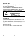
CAUTION !
STATIC ELECTRICITY can damage circuit
boards and electronic components.
S Observe precautions for handling electrostatic-
sensitive devices.
S Use proper static-proof bags and boxes.
ESD
INTRODUCTION
The remote controls and adapters are designed for ESAB's welding equipment with CAN
bus communication.
When the remote control or adapter is connected to the welding equipment, the control
panel is in remote control mode, the buttons and knobs are blocked. The functions can only
be adjusted via the remote control unit.
If the remote control unit is not to be used, it must be disconnected from the welding
equipment, otherwise the equipment will remain in remote control mode.
For more information about the operation of the remote control unit, see the operating
instructions for the control panels.
Only one remote control or adapter may be connected to the welding equipment.

S0740 800 170/E060829/P18
- 4 -
cf07d1
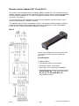
DESCRIPTION OF OPERATION
Terminating resistors
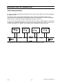
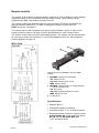
In order to avoid communication interference, the ends of the CAN bus must be terminated
by resistive loads.
The CAN remote controls and CAN adapters have a built-in terminating resistor. This
resistor can be disconnected by removing the jumper from terminal J1 on the CAN adapter
board. See the component positions diagrams on pages 12 and 14.
To check if the terminating resistor of the CAN remote control or CAN adapter is connected:
measure the resistance between pin 3 and 4 of the 4 pole panel plug, or pin L and K of the
12 pole cable plug. The resistor is connected if the resistance is about 120 ohm.
Principal diagram of the CAN bus and connecting up of the terminating resistors

S0740 800 170/E060829/P18
- 5 -
cf07rap2
Remote controls
The remote controls have a software identity, machine ID. The ID defines how the welding
equipment reacts on the commands from the remote control. When starting up the
equipment the MMC unit sends a request for the ID.
The remote controls are delivered with the correct machine ID. Spare part boards are
delivered without machine ID. To read or change the machine ID you need the
ESAT service kit, see page 17.
The control panel of the equipment must have correct software version in order for the
remote control to function correctly. See the specifications for each remote control.
The remote controls have a built-in terminating resistor. This resistor can be disconnected
by removing a jumper from terminal J1 on the CAN adapter board. See the component
position diagram on page 12.
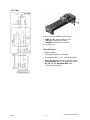
MTA1 CAN
Remote control for MIG/MAG, TIG and MMA
welding.
1
2
3
MIG/MAG: Setting wire feed speed
TIG: Setting current
TIG pulse: Setting pulse current
MMA: Setting current
MIG/MAG: Setting voltage or voltage deviation
+/- from the synergic line
TIG: No function
TIG pulse: Setting background current
MMA: Setting arc force
Locking knob
Specifications
S Machine ID = 4
S Termination resistor connected
S Connection cable: 5, 10, 15 and 25 metres
S Required sofware version for control panels.
AristoPendant U8: 1.20C and there above.
A2, A4, T4, T6, M2, MA4, MA6, U6:
1.21F and there above.

S0740 800 170/E060829/P18
- 6 -
cf07rap2
M1 10Prog CAN
Remote control for MIG/MAG, TIG and MMA
welding.
1
2
3
Choice of one of 10 program selections
MIG/MAG: Voltage deviation +/- from selected
program
TIG and MMA: Setting welding current +/- from
selected program
TIG pulse: Setting pulse current +/- from
selected program
Locking knob
Specifications
S Machine ID = 6
S Termination resistor connected
S Connection cable: 5, 10, 15 and 25 metres
S Required sofware version for control panels.
AristoPendant U8: 1.20C and there above.
A2, A4, T4, T6, M2, MA4, MA6, U6:
1.21F and there above.

S0740 800 170/E060829/P18
- 7 -
cf07rap2
AT1 CAN
Remote control for MMA and TIG welding.
1
2
MMA and TIG: Setting welding current
TIG pulse: Setting pulse current
MIG/MAG: Setting wire feed speed
Locking knob
Specifications
S Machine ID = 3
S Termination resistor connected
S Connection cable: 5, 10, 15 and 25 metres
S Required sofware version for control panels.
AristoPendant U8: 1.20C and there above.
A2, A4, T4, T6, M2, MA4, MA6, U6:
1.21F and there above.

S0740 800 170/E060829/P18
- 8 -
cf07rap2
AT1 CourseFine CAN
Remote control for MMA and TIG welding.
1
2
3
Rough setting
Fine setting
Locking knob
MMA and TIG: Setting of welding current
TIG pulse: Setting of pulse current
MIG/MAG: Setting of wire feed speed
Specifications
S Machine ID = 3
S Termination resistor connected
S Connection cable: 5, 10, 15 and 25 metres
S Required sofware version for control panels.
AristoPendant U8: 1.20C and there above.
A2, A4, T4, T6, M2, MA4, MA6, U6:
1.21F and there above.

S0740 800 170/E060829/P18
- 9 -
cf07rap2
FS 002 CAN
Remote control for TIG welding.
1
2
Potentiometer for setting of welding current,
positions 1 - 10
Foot pedal for weld start and setting of welding
current.
If potentiometer (1) is set at position 10, the
current is set, from min. to max. with the foot
pedal.
If potentiometer (1) is set at position 5, the
current is set, from .min. to 50% of max. current
with the foot pedal.
TIG pulse: Setting of pulse current
Specifications
S Machine ID = 5
S Termination resistor connected
S Connection cable 5 metres, included
S Required sofware version for control panels.
AristoPendant U8: 1.20K and there above.
T4, T6, U6: 1.21O and there above.

S0740 800 170/E060829/P18
- 10 -
cf07rap2
Remote control adapters RA 12 and RA 23
The remote control adapters have a software identity, machine ID. The ID defines how the
welding equipment reacts on the commands from the remote control. Spare part boards are
delivered without machine ID. To read or change the machine ID you need the ESAT
service kit, see page 17.
The control panel of the equipment must have correct software version in order for the
remote control adapter to function correctly.
The adapters have a built-in terminating resistor. This resistor is disconnected on delivery.
It can be connected by short-circuiting the two pins of terminal J1 on the CAN adapter
board. See the component positions diagram on page 14.
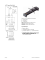
RA 12
Remote control adapter with 12 pole socket. Used
for connecting remote controls to CAN-based
equipment.
Specifications
S Machine ID = 1
S Termination resistor disconnected
S Connection cable: 0.25 metres
S See page 15 for connection possibilities
S Required sofware version for control panels.
AristoPendant U8: 1.20K and there above.
A2, A4, T4, T6, M2, MA4, MA6, U6:
any software version.

S0740 800 170/E060829/P18
- 11 -
cf07rap2
RA 23
Remote control adapter with 23 pole socket.
Used for connecting remote controls to CAN-based
equipment.
Specifications
S Machine ID = 1
S Termination resistor disconnected
S Connection cable: 0.25 metres
S See page 15 for connection possibilities
S Required sofware version for control panels.
AristoPendant U8: 1.20K and there above.
A2, A4, T4, T6, M2, MA4, MA6, U6:
any software version.

S0740 800 170/E060829/P18
- 12 -
cf07rap2
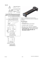
Component positions, CAN adapter and filter board

S0740 800 170/E060829/P18
Remote control adapter
- 13 -
cf07rac3
Remote control adapters RAC 12 and RAC 23
The cable-mounted adapters, RAC 12 and RAC 23 are not sold any more, they are
replaced by the adapters RA 12 and RA 23.
This description applies to remote control adapters connected to
Aristo welding equipment with control panel A2, A4, T4, T6, M2,
MA4, MA6 or U6. When the AristoPendant U8 is used, the functions
are different, see page 15.
The remote control adapters operate correctly with any software version for the control
panels A2, A4, T4, T6, M2, MA4, MA6 or U6.
There is one adapter for remote units with 12 pole connector (RAC 12) and one for units
with 23 pole connector (RAC 23). The only difference between the adapters is the
connection to the remote control.
The remote control adapter has a software identity, machine ID. The ID defines how the
welding equipment reacts on the commands from the remote control. When starting up the
equipment the MMC unit sends a request for the ID, this adapter has ID 1.
The adapters have a built-in terminating resistor. This resistor can be disconnected by
removing the jumper from terminal J1 on the CAN adapter board. See the component
position diagram on page 14. In most connection cases the resistor has to be disconnected,
see page 4.
When a remote control unit is used to set the voltage, the function will be changed to the
setting of current during MMA and TIG welding.
When carrying out TIG welding in pulse mode, the value of the pulse current can be
changed with the remote control.
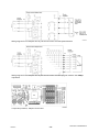
Wiring diagram of the adapter and 12 pole remote control unit with potentiometers

S0740 800 170/E060829/P18
- 14 -
cf07rac3
Wiring diagram for the adapter and 23 pole remote control unit with potentiometers
Wiring diagram for the adapter and 23 pole remote control unit with program selector and voltage
adjustment
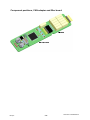
Component positions, adapter circuit board

S0740 800 170/E060829/P18
- 15 -
cf07sum4
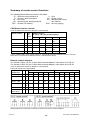
Summary of remote control functions
The following abbreviations are used in the tables:
ID = Remote control machine id V = Volt
C = Current / wire feed speed PC = Pulse current
AF = Arc force BC = Background current
OK = Works for this welding methode - = No function
TIGP = Pulsed TIG welding ARC = Arc-air gouging
CAN based remote controls
U6 in the table below referes to all built-in control panels.
Remote control
ID Con
trol
knob
Software version
U6: 1.21F, U8 1.20C and there above
MIG MMA TIG TIG P ARC
MTA1 CAN 4 2
1
V
C
AF
C
-
C
BC
PC
V
-
AT1 CAN 3 A C C C PC V
AT1 CF CAN 3 A C C C PC V
M1 10Prog CAN 6 P
+
OK
V
OK
C
OK
C
OK
PC
FS002 CAN * 5 - - C PC -
* When FS002 CAN is used control panels T4, T6 and U6 must have software version 1.21O and
there above, U8 must have software version 1.20K and there above.
Remote control adapters
The function of RAC 12, the 12 pole cable-mounted adapter, is the same as for RA 12
The function of RAC 23, the 23 pole cable-mounted adapter, is the same as for RA 23
U6 in the table below referes to all built-in control panels.
Column X referes to the figure below.
Adapter -
remotecont.
ID X U6: software version 1.21F U8: software version 1.20K
MIG MMA TIG TIGP ARC MIG MMA TIG TIGP ARC
RA 12 - 1 pot. 1 G - C C PC V - - - - V
RA 12 - 2 pot. 1 G
B
V
C
C
-
C
-
PC
-
V
-
V
C
AF
C
-
C
BC
PC
V
-
RA 23 - 1 pot. 1 K - C C PC V - - - - V
RA 23 - 2 pot. 1 K
M
V
C
C
-
C
-
PC
-
V
-
V
C
AF
C
-
C
BC
PC
V
-
RA 23 - RS3 1 - OK - - - - OK - - - -
RA 23 -
Aristo 5prog
1 P
+
OK OK OK OK OK OK OK OK
Wiring diagram for connection of remote controls to the remote control adapters

S0740 800 170/E060829/P18
- 16 -
cf07f4
SERVICE INSTRUCTIONS
What is ESD?
A sudden transfer or discharge of static electricity from one object to another. ESD stands for
Electrostatic Discharge.
How does ESD damage occur?
ESD can cause damage to sensitive electrical components, but is not dangerous to people.
ESD damage occurs when an ungrounded person or object with a static charge comes into
contact with a component or assembly that is grounded. A rapid discharge can occur,
causing damage. This damage can take the form of immediate failure, but it is more likely
that system performance will be affected and the component will fail prematurely.
How do we prevent ESD damage?
ESD damage can be prevented by awareness. If static electricity is prevented from building
up on you or on anything at your work station, then there cannot be any static discharges.
Nonconductive materials (e.g. fabrics), or insulators (e.g. plastics) generate and hold static
charge, so you should not bring unnecessary nonconductive items into the work area.
It is obviously difficult to avoid all such items, so various means are used to drain off any
static discharge from persons to prevent the risk of ESD damage. This is done by simple
devices: wrist straps, connected to ground, and conductive shoes.
Work surfaces, carts and containers must be conductive and grounded. Use only antistatic
packaging materials. Overall, handling of ESD-sensitive devices should be minimized to
prevent damage.
CAUTION !
STATIC ELECTRICITY can damage circuit
boards and electronic components.
S Observe precautions for handling electrostatic-
sensitive devices.
S Use proper static-proof bags and boxes.
ESD

S0740 800 170/E060829/P18
- 17 -
cf07f4
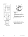
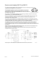
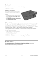
Service aid
We can offer a number of service tools that will simplify the service.
Antistatic service kit
Ordering no. 0740 511 001
The kit makes it easier to protect sensitve
components from electrostatic discharge.
Contents:
S A conductive mat (size 610 x 610 mm)
S A 1.5 metre long ground cable with a
crocodile clip
S An adjustable wrist strap and cable with
an inbuilt protective resistor
Antistatic service kit
ESAT service kit
The software update is made from a PC, it has to be managed by a trained serviceman. For
this a PC program called ESAT, ESAB Software Administration Tool, is needed. The PC is
connected to the welding equipment by a cable connector and a CAN reader. From the
ESAT it is possible to update the software. ESAT also contains service functions by which it
is possible to control, change or read the different functions of the equipment.
For the installation and use of the ESAT you need a PC with operating system Windows.
The ESAT service kit contents:
S CAN adapter with connection cables
S CD with software
S Instruction manual for ESAT
Ordering no:
0458 847 880 PPCAN for connection to the print port of the PC
0458 847 881 USB2CAN for connection to the USB port of the PC
SPARE PARTS
The spare parts list for the MTA1 CAN, M1 10Prog CAN, AT1 CAN,
AT1 CoarseFine CAN, FS 002 CAN, RA12 and RA 23, is published in a separate
document with filename/ordering no.
0459 576 990.

ESAB AB
SE-695 81 LAXÅ
SWEDEN
Phone +46 584 81 000
www.esab.com
081016
ESAB subsidiaries and representative offices
Europe
AUSTRIA
ESAB Ges.m.b.H
Vienna-Liesing
Tel: +43 1 888 25 11
Fax: +43 1 888 25 11 85
BELGIUM
S.A. ESAB N.V.
Brussels
Tel: +32 2 745 11 00
Fax: +32 2 745 11 28
THE CZECH REPUBLIC
ESAB VAMBERK s.r.o.
Vamberk
Tel: +420 2 819 40 885
Fax: +420 2 819 40 120
DENMARK
Aktieselskabet ESAB
Herlev
Tel: +45 36 30 01 11
Fax: +45 36 30 40 03
FINLAND
ESAB Oy
Helsinki
Tel: +358 9 547 761
Fax: +358 9 547 77 71
FRANCE
ESAB France S.A.
Cergy Pontoise
Tel: +33 1 30 75 55 00
Fax: +33 1 30 75 55 24
GERMANY
ESAB GmbH
Solingen
Tel: +49 212 298 0
Fax: +49 212 298 218
GREAT BRITAIN
ESAB Group (UK) Ltd
Waltham Cross
Tel: +44 1992 76 85 15
Fax: +44 1992 71 58 03
ESAB Automation Ltd
Andover
Tel: +44 1264 33 22 33
Fax: +44 1264 33 20 74
HUNGARY
ESAB Kft
Budapest
Tel: +36 1 20 44 182
Fax: +36 1 20 44 186
ITALY
ESAB Saldatura S.p.A.
Mesero (Mi)
Tel: +39 02 97 96 81
Fax: +39 02 97 28 91 81
THE NETHERLANDS
ESAB Nederland B.V.
Amersfoort
Tel: +31 33 422 35 55
Fax: +31 33 422 35 44
NORWAY
AS ESAB
Larvik
Tel: +47 33 12 10 00
Fax: +47 33 11 52 03
POLAND
ESAB Sp.zo.o.
Katowice
Tel: +48 32 351 11 00
Fax: +48 32 351 11 20
PORTUGAL
ESAB Lda
Lisbon
Tel: +351 8 310 960
Fax: +351 1 859 1277
SLOVAKIA
ESAB Slovakia s.r.o.
Bratislava
Tel: +421 7 44 88 24 26
Fax: +421 7 44 88 87 41
SPAIN
ESAB Ibérica S.A.
Alcalá de Henares (MADRID)
Tel: +34 91 878 3600
Fax: +34 91 802 3461
SWEDEN
ESAB Sverige AB
Gothenburg
Tel: +46 31 50 95 00
Fax: +46 31 50 92 22
ESAB international AB
Gothenburg
Tel: +46 31 50 90 00
Fax: +46 31 50 93 60
SWITZERLAND
ESAB AG
Dietikon
Tel: +41 1 741 25 25
Fax: +41 1 740 30 55
North and South America
ARGENTINA
CONARCO
Buenos Aires
Tel: +54 11 4 753 4039
Fax: +54 11 4 753 6313
BRAZIL
ESAB S.A.
Contagem-MG
Tel: +55 31 2191 4333
Fax: +55 31 2191 4440
CANADA
ESAB Group Canada Inc.
Missisauga, Ontario
Tel: +1 905 670 02 20
Fax: +1 905 670 48 79
MEXICO
ESAB Mexico S.A.
Monterrey
Tel: +52 8 350 5959
Fax: +52 8 350 7554
USA
ESAB Welding & Cutting Products
Florence, SC
Tel: +1 843 669 44 11
Fax: +1 843 664 57 48
Asia/Pacific
CHINA
Shanghai ESAB A/P
Shanghai
Tel: +86 21 2326 3000
Fax: +86 21 6566 6622
INDIA
ESAB India Ltd
Calcutta
Tel: +91 33 478 45 17
Fax: +91 33 468 18 80
INDONESIA
P.T. ESABindo Pratama
Jakarta
Tel: +62 21 460 0188
Fax: +62 21 461 2929
JAPAN
ESAB Japan
Tokyo
Tel: +81 45 670 7073
Fax: +81 45 670 7001
MALAYSIA
ESAB (Malaysia) Snd Bhd
USJ
Tel: +603 8023 7835
Fax: +603 8023 0225
SINGAPORE
ESAB Asia/Pacific Pte Ltd
Singapore
Tel: +65 6861 43 22
Fax: +65 6861 31 95
SOUTH KOREA
ESAB SeAH Corporation
Kyungnam
Tel: +82 55 269 8170
Fax: +82 55 289 8864
UNITED ARAB EMIRATES
ESAB Middle East FZE
Dubai
Tel: +971 4 887 21 11
Fax: +971 4 887 22 63
Representative offices
BULGARIA
ESAB Representative Office
Sofia
Tel/Fax: +359 2 974 42 88
EGYPT
ESAB Egypt
Dokki-Cairo
Tel: +20 2 390 96 69
Fax: +20 2 393 32 13
ROMANIA
ESAB Representative Office
Bucharest
Tel/Fax: +40 1 322 36 74
RUSSIA
LLC ESAB
Moscow
Tel: +7 095 543 9281
Fax: +7 095 543 9280
LLC ESAB
St Petersburg
Tel: +7 812 336 7080
Fax: +7 812 336 7060
Distributors
For addresses and phone
numbers to our distributors in
other countries, please visit our
home page
www.esab.com
-
 1
1
-
 2
2
-
 3
3
-
 4
4
-
 5
5
-
 6
6
-
 7
7
-
 8
8
-
 9
9
-
 10
10
-
 11
11
-
 12
12
-
 13
13
-
 14
14
-
 15
15
-
 16
16
-
 17
17
-
 18
18


ESAB AT1 CAN User manual
- Type
- User manual
- This manual is also suitable for
Ask a question and I''ll find the answer in the document
Finding information in a document is now easier with AI
Related papers
-
ESAB ESAT ESAB Software Administration Tool Software version 1.3 User manual
-
-
-
ESAB T1 Foot CAN User manual
-
-
-
-
-
-