Page is loading ...

GE
Lighting Solutions
imagination at work
(BL42, BL44 and BL45 Series)
Features
• Long life (50,000 hour rated life)
• 5 year warranty
• Dry location rated
Lumination
TM
LED Luminaires
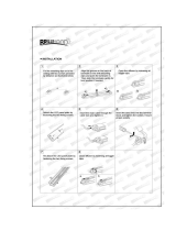
Installation Guide
BEFORE YOU BEGIN
Read these instructions completely and carefully.
Save These Instructions
Use only in the manner intended by the manufacturer. If you have any questions, contact the manufacturer.
WARNING/AVERTISSEMENT
RISK OF ELECTRIC SHOCK
• Turn power off before inspection, installation or removal.
• Properly ground electrical enclosure.
RISK OF FIRE
• Follow all NEC and local codes.
• Use only UL approved wire for input/output connections.
Minimum size 18 AWG (0.75mm
2
).
• Type IC, inherently protected.
RISQUES DE DÉCHARGES ÉLECTRIQUES
• Coupez l’alimentation avant d’’inspecter, installer ou déplacer le luminaire.
• Assurez-vous de correctement mettre à la terre le boîtier d’alimentation électrique.
RISQUES D’INCENDIE
• Respectez tous les codes NEC et codes locaux.
• N’utilisez que des ls approuvés par UL pour les entrées/sorties de
connexion. Taille minimum 18 AWG (0.75mm
2
).
• Type IC, protection inhérente.
Provided in the package are:
• Luminare
• Universal mounting bracket (4 pieces)
• M3x12mm screws for mounting bracket installation (8 pieces)
• M3 wingnut (8 pieces)
• Ceiling grid safety screw for grid and bracket xing (4 pieces)
• Primary diffuser
• Optional low glare diffuser with protective lm
Tools and components required:
• For end cover install: Philips headed screwdriver
• Rigid (RMC) or exible (FMC) metal conduit for supply connection
• UL/cUL approved twist-on-wire connectors, min. 18 AWG
• UL/cUL approved conduit ttings for 1/2” conduit trade
size (2 pieces)

2
3A 3B
Remove end cover closest to the cable glands.
Retain star washer for reinstalling end cover.
Two diffusers: Slide both diffusers into base
of luminaire, making sure the diffuser with the
green protective lm is placed on the bottom.
One diffuser: Slide diffuser into base of luminaire.
1
Carefully unpack unit from its packaging. Properly
inspect for defects before installing. Wear
work gloves to prevent dirt and oil from being
transferred to the luminaire.
Bottom: Diffuser with
green lm faces up.
Remove before sliding in.
Top: Diffuser with no lm
Retain star washer
Two diffusersOne diffuser
Diffuser Installation
Prepare Electrical Wiring
Electrical Requirements
• The LED driver must be supplied with 100-277 VAC, 60 Hz and connected to an individual properly
grounded branch circuit, protected by a 15 or 20 ampere circuit breaker. Use min. 600V 75°C supply conductor.
Grounding Instructions
• The grounding and bonding of the overall system shall be done in accordance with National Electric Code
(NEC) Article 600 and local codes.

Wiring for Lutron Controller
Lutron
dimming wires
3
Optional: If using a dimmer, connect black and red
wires of the dimming line to the PSU dimming wires
with twist-on connectors. Use the appropriate wires
for your dimming type according to diagrams below.
4
Replace cover using at least one star washer under
countersunk screw head.
Star washer
1 2
Connect the AC line to the black (line) and to the
two white (neutral) input wires of the LED Driver
using 18-14 AWG (0.82-2.08 mm
2
) twist-on wire
connectors. Connect AC line green ground wire to
Troffer ground wire using twist-on connectors.
For Lutron dimming, connect black and red wires
of the dimming line to the two purple Lutron
dimming wires with twist-on connectors.
Electrical Connections
1
Remove knockout closure to insert AC line.
Optionally, remove both knockout closures if
installing a dimming line.
2
Connect the AC line to the black (line) and white
(neutral) input wires of the LED Driver using 18-14
AWG (0.82-2.08 mm
2
) twist-on wire connectors.
Connect AC line green ground wire to Troffer
ground wire using twist-on connectors.
Dimming line
(optional)
AC line
AC line

Wiring Diagrams
Follow diagram A for 1-10V, diagram B for DALI or diagram C for Lutron dimming.
At output side of LED driver, make appropriate connections using twist-on wire connectors.
Follow lighting controller installation instructions.
Optional Installation: 1-10 Volt Dimming or DALI Lighting Controller
Line
Neutral
Ground
DALI 1 violet
DALI 2 violet/white
PSU
(1-10V) -
DALI
DALI/(1-10V) +
Line
Neutral
Ground
Line
Neutral
Ground
(1-10) + violet
(1-10) - grey
PSU
(1-10V) -
DALI
DALI/(1-10V) +
Line
Neutral
Ground
DALI wiring diagram
Lutron wiring diagram
B
C
1-10V wiring diagram
A
Line
Neutral
Ground
EcoSystem 1
EcoSystem 2
PSU
Lutron
(1-10V) - (1-10V) -
DALI
DALI/(1-10V) +
(1-10V) +
Line
Ground
Neutral
Neutral
Ground
Switched Hot
Line
EcoSystem 1
EcoSystem 2
Luminaire Installation
With the supplied universal bracket the product
is compatible with the following USG type grids:
DX, DXI, DXT, DXF, DXM.
Reference diagram (right) to determine which
hole to use for a given grid.
Safety screw holes.
One is needed,
more are optional.
DX
DXT(F)
DXI
DXI
DXF
DXF
DXT(F)
DX
DXM/
DXT(G)
DXM/
DXT(G)

5
For added safety, use additional celing grid screws
to permanently x bracket to grid.
2
4
1
3
Fasten mounting brackets over screws by using
two M3 wingnuts for each bracket but do not
tighten them at this point. Note that bracket aps
have to be aligned with the groove.
Fasten the wingnuts of the mounting brackets by
hand, being careful not to strip the threads.
Slide four M3x12 bracket mounting screws into
housing groove on each side (eight screws per
housing are required). If the screw head cannot
pass through end cover groove, remove end
covers and slide the screw head directly into the
housing groove, then re-install end covers.
Mount xture into grid system.
One safety screw is
mandatory, additional
screws are optional
Do not
tighten yet
Always use two
screws per bracket
WARNING
Risk of Injury. Improper mounting bracket
installation may cause injury or property damage.

This device complies with Part 15 of the FCC Rules. Operation is subject to the following two conditions: (1) This device may not cause harmful
interference, and (2) this device must accept any interference received, including interference that may cause undesired operation. This Class
[A] RFLD complies with the Canadian standard ICES-003. Ce DEFR de la classe [ A ] est conforme ‡ la NMB-003 du Canada.
Note: This equipment has been tested and found to comply with the limits for a Class A digital device, pursuant to part 15 of the FCC Rules.
These limits are designed to provide reasonable protection against harmful interference when the equipment is operated in a commercial
environment. This equipment generates, uses, and can radiate radio frequency energy and, if not installed and used in accordance with the
instruction manual, may cause harmful interference to radio communications. Operation of this equipment in a residential area is likely to
cause harmful interference in which case the user will be required to correct the interference at his own expense.
IND034-051713
1326613
GE Lighting Solutions • 1-888-MY-GE-LED • www.gelightingsolutions.com
1-888-69-43-533
GE Lighting Solutions, LLC is a subsidiary of the General Electric Company. Lumination is a trademark of GE Lighting Solutions, LLC. The GE brand and logo are trademarks of the General Electric Company.
© 2013 GE Lighting Solutions, LLC. Information provided is subject to change without notice. All values are design or typical values when measured under laboratory conditions.
Troubleshooting
Symptom Solution
Luminaire does not light • Check input voltage and check power supply input/output connections.
• Check circuit breaker.
Luminaire is dim • Maximum recommended supply wire length is exceeded. Refer to EP147 installation guide
for Maximum Driver Remote Mounting Distance.
Luminaire is blinking • Ensure power supply temperature does not exceed its maximum rating.
• Refer to the tc point located on power supply.
Luminaire does not dim • Check dimming wire connection.
/