Page is loading ...

www.acclaimlighting.com
Flex Tube™
User guide


1
www.acclaimlighting.com
CONTENTS
INTRODUCTION ......................................................2
Welcome 2
Safety 2
INSTALLATION ......................................................... 3
Flex Tube orientation 3
Bending a Flex Tube 4
Cutting a Flex Tube 4
Connection and mounting kits 5
Feed cable kit 5
End cap kit 8
Self-locking mounting channel kit 10
Flexible link kit 12
Seamless link kit 16
Connecting and controlling Flex Tubes 20
FURTHER INFORMATION ...................................... 22
Troubleshooting 22
Flex Tube specifications 23
Limited warranty 24

2
www.acclaimlighting.com
INTRODUCTION
WELCOME
Welcome to the Flex Tube range from Acclaim Lighting. These flexible LED powered strips
produce a greatly homogenized light output along their full length to provide a viable
alternative to other linear light sources, such as neon or cold cathode. Designed from the
outset for external applications, Flex Tubes are rated to IP68 and can be submersed up to 3
feet (1m) in depth.
There are three main types of Flex Tube available:
• A standard version with bare ends and no connection points. A feed cable kit must be
added to provide the connection.
• An injection molded (IM) variant that has the feed connection pre-installed on its side.
• An injection molded (IM) variant that has the feed connection pre-installed on its rear face.
All three of these Flex Tube types are available with two LED color options:
• Single color (SC) - Has a two-wire connection for 24VDC static powering or 24V PWM for
dimming.
• Multi-color (RGB) versions - Has a four-wire (common anode) connection for 24V PWM
dimming.
A range of dimming driver and static power supply options are available from Acclaim
Lighting. See the section Connecting and controlling Flex Tubes on page 20 and also
www.acclaimlighting.com for further details.
Flex Tube with injection
molded (IM) feed connection
on the side face
Flex Tube with injection
molded (IM) feed connection
on the rear face
SAFETY
• Ensure that the power input is supplied from a correctly fused and environmentally
protected location.

3
www.acclaimlighting.com
INSTALLATION
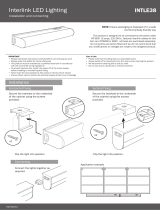
FLEX TUBE ORIENTATION
When attaching connections to a Flex Tube it is important to know which way it is
orientated. Each Flex Tube has an 01 end and an 02 end; these are usually marked at each 4”
(10cm) cut point:
Each connector is similarly marked with
either a 01 or a 02. You must ensure that an
identically labeled connector is used, so that its
designation matches that of the Flex Tube into
which it is being inserted. Failure to do this will
mean that the connections become reversed.
Flex Tube
RGB
Flex Tube
SC
Cut point mark plus signal labeling
(shown every 1 meter)
Cut point mark
(shown every 10cm)
Ensure that the number
designations on the
connector matches that
on the cut mark
WHEN MOUNTING ON THE SIDES OR UNDERSIDES OF SURFACES
We recommend that you add small dots of
silicone sealant along both sides of the Flex
Tube (to overlap the tape edge and mounting
surface) using Dow Corning 700 or equivalent.
This will provide additional stability and help
to prevent any separation of the tube from the
mounting surface over time. The silicone dots
are best applied once the Flex Tube is fixed in
place; then the whole installation should not be
disturbed until it the sealant has fully cured.
02
Sealant
dots

4
www.acclaimlighting.com
CUTTING A FLEX TUBE
Each Flex Tube is marked
every 4” (10cm) with cut
marks. It is important
that cuts are only made
at these points to ensure
internal components are
not damaged and also that
the connection terminals are
readily available.
All cuts should be made using
the special shears supplied
within the toolkit.
Minimum
bend
radius:
5” (127mm)
BENDING A FLEX TUBE
Flex Tubes are designed to be bent, in either
direction, of one axis only - to a minimum
bend radius of 5” (127mm):
Flex Tubes are NOT designed to
be bent in the other direction.
Damage will be caused
to the internal
circuitry.
Avoid twisting Flex Tubes at
all times. Damage will
be caused to the
internal
circuitry.

5
www.acclaimlighting.com
FEED CABLE KIT
This kit adds a connection point to a Flex Tube. There are two types of Feed cable kit: SC for
single color Flex Tubes and RGB for multi-color Flex Tubes.
KIT CONTENTS
TO INSTALL A FEED CABLE KIT
1 Check the orientation of the Flex Tube (see page 3) and, if necessary, carefully cut the Flex
Tube to the correct length (see page 4).
Flex Tube
front face
2 Fit the grip clip to the 01
end of the Flex Tube so
that wraps tightly around
the rear face...
...and its back edge is aligned with
the cut edge of the Flex Tube.
Collar
[x1]
Screw
[x4]
01 feed connector
with silicone gasket
[x1]
Grip clip
(end-type)
[x1]
CONNECTION AND MOUNTING KITS
To make your Flex Tube installation as adaptable as possible there are a range of connection
and mounting kits available, including the following:
• Feed cable kit - used for linking a Flex Tube with driver circuitry. See below
• End cap kit - used to seal an open end of Flex Tube. See page 8
• Self-locking mounting channel - used to fix a Flex Tube to a surface. See page 10
• Flexible link kit - used to link two Flex Tubes with a flexible gap. See page 12
• Seamless link kit - used to link two Flex Tubes with no gap. See page 16
Align the back edge
of the grip clip with
the cut edge of the
Flex Tube

6
www.acclaimlighting.com
Four screw
holes in the
collar
Introduce
the collar
onto the clip
at roughly 45
degrees
5 From the toolkit choose the larger of the
two insert assist tools. Place the tip of the
tool against the underside of the circuit
board within the Flex Tube. Carefully push
the tool into the Flex Tube (to a maximum
depth of 0.5”, 12.5mm) so that it creates a
small cavity in the flexible material below
the circuit board.
Carefully push the tool
between the bottom edge
of the circuit board and the
exible material (to a depth
of 0.5”, 12.5mm)
6 Check that the silicone
gasket is correctly
positioned over the
contacts of the feed connector.
The gasket is pre-greased; make sure
no grease gets on the contacts.
3 Place the collar onto the Flex Tube
(with its four screw holes facing
towards the cut edge) and then
slide it onto the grip clip - you
will find it easier to introduce the
collar at approximately 45 degrees
before sliding it along the Flex
Tube. The clip has tapered sides
and will pull the collar in tighter as
it slides towards the end tabs.
4 Once the collar is in place, press the front face of the tape
to ensure that the clip is fully seated into the collar.
Check the silicone
gasket is in place and
ensure the contacts are
clean of grease

7
www.acclaimlighting.com
7 Orientate the 01 feed connector so that
its ‘01’ label is uppermost, then carefully
push its contact prongs into the cavity
that you created with the tool. The four
screw holes of the feed connector should
align with those in the collar.
Ensure the
‘01’ label is
uppermost
8 Insert the four screws and tighten
them evenly (in small increments)
using the order 1-2-3-4-1-2, etc.
shown right, so that the end
cap does not become skewed
in any direction. Take care not to
overtighten the screws.

8
www.acclaimlighting.com
Four screw
holes in the
collar
Introduce
the collar
onto the clip
at roughly 45
degrees
END CAP KIT
This kit is used to seal off the bare end of a Flex Tube.
KIT CONTENTS
TO INSTALL AN END CAP KIT
1 Check the orientation of the Flex Tube (see page 3) and, if necessary, carefully cut the Flex
Tube to the correct length (see page 4).
Flex Tube
front face
2 Fit the grip clip to the
end of the Flex Tube so
that wraps tightly around
the rear face...
Align the back edge
of the grip clip with
the cut edge of the
Flex Tube
...and its back edge is aligned with
the cut edge of the Flex Tube.
Place the collar onto the Flex Tube
(with its four screw holes facing
towards the cut edge) and then
slide it onto the grip clip - you
will find it easier to introduce the
collar at approximately 45 degrees
before sliding it along the Flex
Tube. The clip has tapered sides
and will pull the collar in tighter as
it slides towards the end tabs.
Collar
[x1]
Screw
[x4]
Grip clip
(end-type)
[x1]
Silicone
gasket
[x1]
End cap
[x1]
3 Once the collar is in place, press the front face of the
tape to ensure that the clip is fully seated into the collar.

9
www.acclaimlighting.com
4 Place the pre-greased
silicone gasket squarely
onto the end face of the
Flex Tube.
5 Place the end cap onto
the end of the Flex Tube
so that the four screw
holes of the end cap align
with those in the collar.
Also ensure the gasket sit
neatly within the face of
the end cap.
6 Insert the four screws and tighten
them evenly (in small increments)
using the order 1-2-3-4-1-2, etc.
shown right, so that the end
cap does not become skewed
in any direction. Take care not to
overtighten the screws.

10
www.acclaimlighting.com
SELF-LOCKING MOUNTING CHANNEL KIT
These kits are used to mount Flex Tubes onto solid surfaces.
KIT CONTENTS
TO INSTALL A SELF-LOCKING MOUNTING CHANNEL KIT
1 Choose appropriate screws and fixings for the intended mounting surface. The limited
space within the mount channel restricts the screws used to the following dimensions:
2 Attach the mount channel to the
intended surface, taking all appropriate
precautions as you do so.
• 5cm mounts have just one hole.
• 1 meter mounts have five holes,
spaced 20cm apart.
Grip clip
(mount-type)
Mount channel
(5cm or 1 meter lengths)

11
www.acclaimlighting.com
3 If they are not already in
position, place the grip
clip(s) into the mount
channel.
4 Push the Flex
Tube (front face
outwards) fully
into the mount
channel until it
engages fully
with the grip
clip(s).
• If you should need to remove
the Flex Tube, press and hold
the two raised buttons while
you gently pull the Flex Tube
out from the mount channel.
Flex Tube
front face

12
www.acclaimlighting.com
FLEXIBLE LINK KIT
This kit allows you to join two lengths of Flex Tube with a 10” (25cm) flexible cable link
between them. There are two types of flexible link kit: SC for single color Flex Tubes and RGB
for multi-color Flex Tubes.
IMPORTANT: The maximum overall length for any linked Flex Tubes is 32 feet (10 meters).
KIT CONTENTS
TO INSTALL A FLEXIBLE LINK KIT
1 Check the orientation of both Flex Tubes (see page 3). Most often power is applied to the
01 end of a Flex Tube and exits at its 02 end ready to feed the next Flex Tube.
If necessary, carefully cut the Flex Tube(s) to the required length(s) (see page 4).
Flex Tube
front face
2 Fit one of the grip clips
to the 01 end of one of
the Flex Tubes so that
wraps tightly around the
rear face...
...and its back edge is aligned with
the cut edge of the Flex Tube.
Align the back edge
of the grip clip with
the cut edge of the
Flex Tube
Collar
[x2]
Grip clip
(end-type)
[x2]
Tube of
sealant grease
[x1]
Interlink cable with
silicone gaskets
[x1]
Screw
[x8]

13
www.acclaimlighting.com
3 Place the collar onto the Flex Tube
(with its four screw holes facing
towards the cut edge) and then
slide it onto the grip clip - you will
find it easier to introduce the collar
at approximately 45 degrees before
sliding it along the Flex Tube. The clip
has tapered sides and will pull the
collar in tighter as it slides towards the
end tabs.
5 Repeat step 2 for the 02
end of the other Flex Tube.
Four screw
holes in the
collar
Introduce
the collar
onto the clip
at roughly 45
degrees
4 Once the collar is in place, press the front face of the tape
to ensure that the clip is fully seated into the collar.

14
www.acclaimlighting.com
Apply a lm of grease
but keep it o the
contacts
6 From the toolkit choose the larger of the
two insert assist tools. Place the tip of the
tool against the underside of the circuit
board within the Flex Tube. Carefully push
the tool into the Flex Tube (to a maximum
depth of 0.5”, 12.5mm) so that it creates a
small cavity in the flexible material below
the circuit board.
7 Repeat step 6 for the other Flex Tube.
Carefully push the tool
between the bottom edge
of the circuit board and the
exible material (to a depth
of 0.5”, 12.5mm)
Ensure the
‘01’ label is
uppermost
8 At each end of the
Interlink cable, check
that the silicone gaskets
are correctly positioned
over the contacts of the
connectors and place a thin film
of grease to cover the front face of
the gasket - take care to keep the grease off the
connector contacts.
9 The two connectors are labeled ‘01’ and
‘02’. You need to ensure that the correct
connector is used for each length of Flex
Tube. Orientate the 01 connector so that
its ‘01’ label is uppermost, then carefully
push its contact prongs into the cavity that
you created in the 01 end of the Flex Tube.

15
www.acclaimlighting.com
10 Insert the four screws and tighten
them evenly (in small increments)
using the order 1-2-3-4-1-2, etc.
shown right, so that the end
cap does not become skewed
in any direction. Take care not to
overtighten the screws.
11 Repeat steps 9 and 10 for the ‘02’ connector at the
other end of the Interlink cable and the other Flex
Tube.

16
www.acclaimlighting.com
SEAMLESS LINK KIT
This kit allows you to rigidly join two lengths of Flex Tube with no perceptible gap between
them. There are two types of seamless link kit: SC for single color Flex Tubes and RGB for
multi-color Flex Tubes.
IMPORTANT: The maximum overall length for any linked Flex Tubes is 32 feet (10 meters).
KIT CONTENTS
TO INSTALL A SEAMLESS LINK KIT
1 Check the orientation of both Flex Tubes (see page 3). Most often power is applied to the
01 end of a Flex Tube and exits at its 02 end ready to feed the next Flex Tube.
If necessary, carefully cut the Flex Tube(s) to the required length(s) (see page 4).
2 From the toolkit choose the larger of the
two insert assist tools. Place the tip of the
tool against the underside of the circuit
board within the Flex Tube. Carefully push
the tool into the Flex Tube (to a maximum
depth of 0.5”, 12.5mm) so that it creates a
small cavity in the flexible material below
the circuit board.
3 Repeat step 2 for the other Flex
Tube.
4 Carefully insert one end
of the Interlink board into
the into the cavity that you
created in the end of either
Flex Tube.
IMPORTANT: Be very
careful not to ex or
bend the Interlink board.
Grip clip
(mid-type)
[x2]
Steel joiner
[x1]
Interlink
board
[x1]
Silicone
gasket
[x1]
Tube of
sealant grease
[x1]

17
www.acclaimlighting.com
01
GREASE
Grip clip end tabs furthest away
from the edge of the Flex Tube
5 Place a thin film of grease to cover
the cut face of the Flex Tube - take
care to keep the grease off the
interlink board contacts.
7 Place one of the grip
clips onto the Flex Tube.
Ensure that the tabs are
furthest from the cut
edge of the Flex Tube
while the opposite edge
of the clip aligns with
the cut edge of the Flex
Tube.
Align this side
with the cut edge
of the Flex Tube
8 Place the second grip
clip onto the other
Flex Tube, following
the guidelines given in
step 6.
6 Fit the silicone gasket
onto the Interlink board
such that it aligns with
the profile of the Flex
Tube - use the insert
assist tool to create a slot
in the gasket.

18
www.acclaimlighting.com
9 Carefully
insert the
end of the
interlink
board into
the cavity
created within
the second Flex
Tube.
Note: It is important that you
do not flex the interlink board at all
during this process, so it is best carried out
on a flat surface.
Do not push the two Flex Tubes all the way together
at this stage.
10 Position the
steel joiner
alongside the
Flex Tubes
and begin
to carefully
introduce the two
Flex Tapes (plus clips
and interlink board) into its
open side.
As you do this, adjust the gap
between the Flex Tubes so that
the two raised clip notches on
each side of each grip clip align with
the slot openings of the joiner (marked as
A, B, C and D on the diagram above).
At all times minimize the lateral movement of
the Flex Tubes in order to reduce the chances of
damaging the fragile interlink board.
Align the clip notches
(highlighted here in blue) with
the slot openings A, B, C and D
Locking tab
/