Page is loading ...

Concur installation guide

CONCUR INSTALLATION GUIDE | 2
amqsolutions.com
COMPONENTS
A B C
Right
x1
Right
x1
Left
x1
Middle Frame Left
x1
D E
M6x35
x4
M5x35
x4
G H IF
M4x18
x2
M5x25
x6
Castors
x4
Worksurface
Support
OPTIONAL (MODESTY PANEL)
J K L L-1
M6x10
x4
Panel Brackets
x2
Modesty
Panel
M5x10
x2
OPTIONAL (GANGING DEVICE)
M N O
M4x18
x7

CONCUR INSTALLATION GUIDE | 3
amqsolutions.com
PHASE 1 | Concur Assembly
Step 1
Select one leg (A) and attach it to the middle
frame (B) with one of the D screws. Tighten a bit
but not completely.
Insert a second D screw and loosely tighten.
Now tighten both (D) screws completely.
Next, tighten the (E) screws in the same method
you used for the (D) screws, leaving loose until
all 4 are in place and then tightening.
Repeat with the other leg.
Step 2
Twist to insert the (C) push button bracket,
followed by the button cover. Repeat on the
other side.
Step 4
Turn the work surface upside down and center
align the Worksurface Support (F) using the (G)
screws (x2). Now turn the leg and middle frame
assembly upside down. Attach the worksurface to
the cantilevers of the frame assembly using the (I)
screws (x6). Insert the castors firmly into the legs
until locked in place.
Step 5
Turn your finished CONCUR table over to use.
1
2
3
4
5
If Installing Modesty Panel:
Step 3
Connect the Panel Brackets (K) to the middle
frame (B), locking it with the (L-1) screws (x2).
Connect the Modesty Panel (J) and panel
brackets with the (L) screws (x4).
L
L-1
J
L
K
K
L
L-1
L-1
D
E
D
D
E
E
B
A
A
C
F
H
H
H
H
G
I
I
Detail
Detail
Detail
Detail

CONCUR INSTALLATION GUIDE | 4
amqsolutions.com
OPTIONAL | Ganging Device
O
N
N
O
Screw M4 x 18.0L
x7
M
M
M
Rotary lock
Rotary lock
N
O
N
O

CONCUR INSTALLATION GUIDE | 5
amqsolutions.com
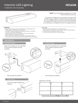
OPTIONAL | Interlink
Step 1
Install Interlink IQ Power/Data Units into
worksurface. (Diagram shows a Mho Unit with a
Interlink IQ system)
NOTE: A Furniture Power Distrubution Unit is
not for permanent installation as part of the
building structure and not for mounting in a
permanently-installed furnishing such as a
fixed countertop.
Step 2
Connect Maximum of 8 of any combination
Interlink IQ Power/Data and/or By Pass Units to
Interlink IQ Control Box.
Light will be green
when unit is working
Snap to engage or
depress to disconnect
Interlink IQ
Control Box
Keying
Interlink IQ
Control Box
Power Cord
Step 3
Determine mounting location. Interlink IQ Control
Box can be secured to worksurface by included
industrial hook & loop.
Step 4
Use included clips to secure cords.
Industrial hook & loop

CONCUR INSTALLATION GUIDE | 6
amqsolutions.com
NOTE: The Interlink IQ System monitors for
correct number of Units. Once connected
to power, light on Interlink IQ Control box
will be green. If more than 8 Interlink IQ
Power/Data or By Pass Units are plugged
into the Interlink Control Box, power will
shut down and light will be red.
To reset, disconnect extra Unit(s) and
unplug Interlink IQ Control Box from power
for 15 seconds. Reconnect power to the
Interlink IQ Control Box. The Indicator light
should be green.
NOTE: If Interlink IQ System is overloaded,
the circuit breaker will trip and will have to
be reset.
Interlink IQ Control Box
Indicator Light
OPTIONAL | Interlink

Please contact [email protected] if you are
missing any parts, have difficulty with assembly,
or have any product related questions.
/